Week 13: Networking & Communications
The goal of this week was to use different types of communications and connections to link different items. I chose to try to connect multiple OLED screen over I2C, as well as my sensor and a separate ATtiny412 just to understand the week a little better. Files for the PCBs can be found here.
Assignment
Individual Assignment:
- Design, build, and connect wired or wireless node(s) with network or bus addresses and local input &/or output device(s).
Group Assignment:
- Send a message between two projects.
I2C Multiplexing
I started out by testing the mutliplexing potential of I2C for the OLEDs, and since I had seen a couple videos while sutdying my final project about doing this exact same thing, I knew it was possible. This website helped in understanding the fundamental of what I had to do with my code, so I modified the code from Inputs week by removing the aspects that related to the sensor and making a second OLED object named ‘oled2’. Then, I defined a second address for the I2C, as this was both a required part of doing I2C and it needed to be different from the other OLED since two items in I2C cannot have the same address.
#include <Wire.h>
#include <Adafruit_Sensor.h>
#include <Adafruit_BNO055.h>
#include <utility/imumaths.h>
#include "SSD1306Ascii.h"
#include "SSD1306AsciiWire.h"

#define I2C_ADDRESS 0x3C
#define I2C_ADDRESS2 0x3D

#define RST_PIN -1


SSD1306AsciiWire oled;
SSD1306AsciiWire oled2;

void setup()
{
  Wire.begin();
  Wire.setClock(400000L);

  #if RST_PIN >= 0
  oled.begin(&Adafruit128x64, I2C_ADDRESS, RST_PIN);
  oled2.begin(&Adafruit128x64, I2C_ADDRESS2, RST_PIN);
#else // RST_PIN >= 0
  oled.begin(&Adafruit128x64, I2C_ADDRESS);
  oled2.begin(&Adafruit128x64, I2C_ADDRESS2);
#endif // RST_PIN >= 0

  oled.setFont(Adafruit5x7);
  oled2.setFont(Adafruit5x7);
  Serial.begin(9600);
  oled.println("test");
  oled2.println("test");

  oled.println("Double OLED Test"); oled.println("");
  oled.print("test 2");
  oled2.print("test2");

  delay(1000);
}

void loop() {

}
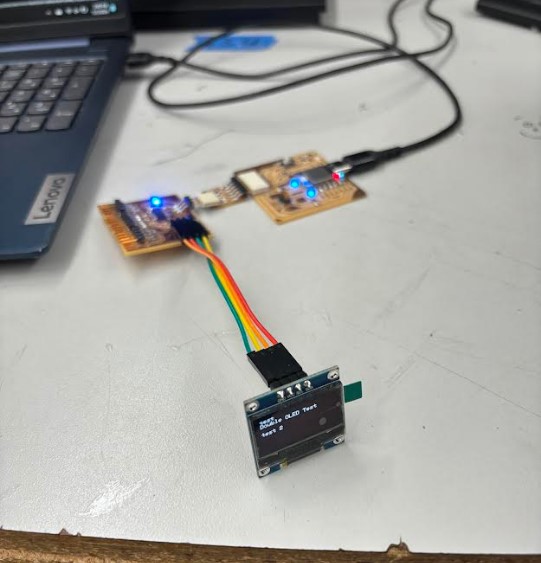
Using the board I made last week, I hooked up two OLEDs - one to the preexistant spot for the OLED, and the other using the pins that were meant for the sensor, as those had already been I2C.

Once I got this working, I decided to try and make my own board for this week, and it was at this point that I chose to incorporate an ATtiny412 thanks to the inspiration of Connor Cruz.
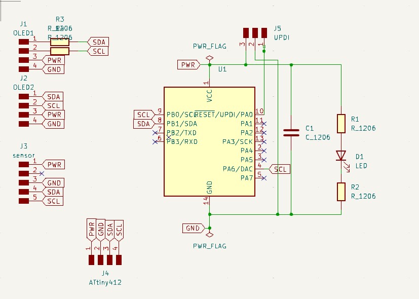
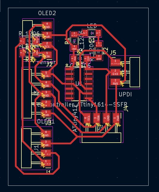
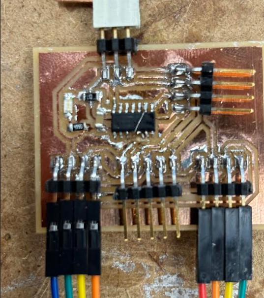
I went into KiCad and made a simple schematic + PCB board design for the board that I wanted to create.
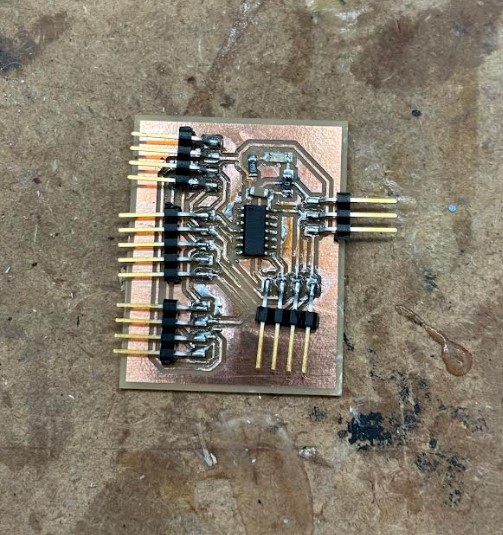
Next, I milled out the board using procedures described in previous weeks on Bantam milling software. I did not experience any issues with this process, which was a welcome change to how it can sometimes be very difficult to operate due to simple errors.

Then, I soldered on the following components:
|---------|--------| | Component | Quantity | | ATtiny1614 | 1 | | 1uF capacitor | 1 | | Blue LED | 1 | | 499 Ohm resistor | 1 | | 0 Ohm resistor | 3 | | 1x03 Conn. Header pins | 1 | | 1x04 Conn. Header pins | 3 | | 1x05 Conn Header pins | 1 |
This process sadly took longer than expected, since I had initially soldered the chip on with the incorrect orientation and had to fix it. Additionally, the solder paste was not available for the first half of the process, which made it tough to work with the small pads of the chip.
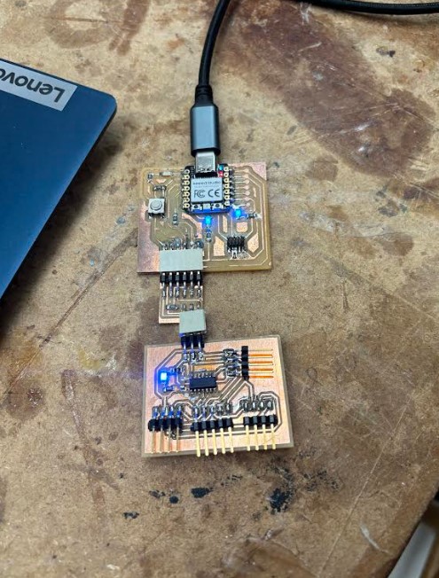
Once it was all together, I plugged it into the QuenTorres board and UPDI convertor that I had from previous weeks, and saw that the indiciator LED was turning on.
Then, I plugged in the 2 OLEDs using jumper cables and attempted to get it to work properly, but I recieved an odd error that I had not seen before.
pymcuprog.pymcuprog_errors.PymcuprogError: Unexpected number of bytes in response: 0 byte(s) expected 1 byte(s)
I tried to search this up to no avail, so I began to look into the board itself for solutions. At first, I tried soldering on a new 1614 chip, as well as redo a significant amount of the soldering. During this, since I had crossed over a pad in the creation of my board, Mr. Durret, one of my instructors, told me to cut that led off and use a stripped piece of wire to connect the pieces instead.
After doing this, I began to recieve a new error that I was more familiar with:
UPDI initialization failed
I knew this meant that the UPDI pin was not working, so I tried to probe around with a multimeter to find faulty connections, and while it would sometimes return odd results, the results were too sporatic and random to gleam any useful information from them. I turned to my old documentation and board for Inputs Week and saw that the chip I was using there, where it worked, was slightly different from the one I was using now.
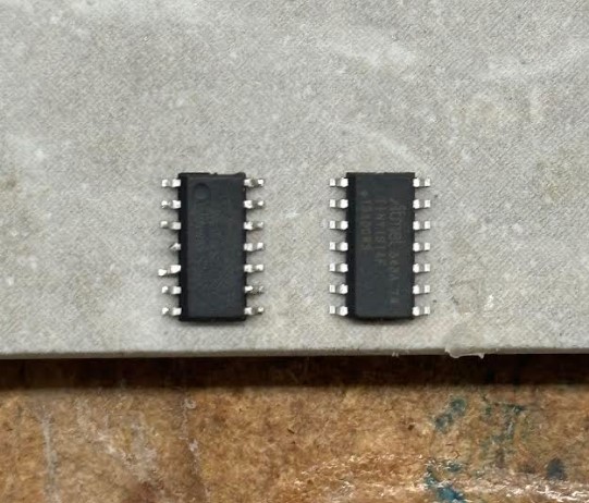
I saw that the chip I had had a slight indent in the spot meant to display the orientation, so I soldered on a new board of that variety. When I plugged it back in and ran the above code just as a test, it uploaded perfectly fine and was a big sign of relief. I had simply run the code without the OLEDs connected, so I went to do that next on the next day. When neither of the OLEDs turned on, I started inspecting the wiring and moved some things around, and saw that one OLED would turn on whenever I put it on the connnections to what was meant to be the spot for the ATtiny412 later on.
After inspecting a bit more, I saw that the small wire Mr. Durrett had helped put on had come off, and I had not seen it since it was already quite small. I soldered on a wire I thought would be better, as it had less potential to come off.

I uploaded the program and saw that they were both working now.
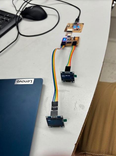
The next step was to integrate the sensor from Inputs week, so I modified the code at the bottom of the program to try to print out the message for the orientation, this being the data type I wanted to have on one of the OLEDs, onto the second OLED. The initial struggle I faced was the double values appearing for the values that were not used on each of the OLEDs, meaning that the first OLED had all the standard data but the double values for where orientation would normally be, and vice versa for the other OLED. I eventually fixed this by changnig the loop function to print out the values of each reading individually rather than having one print statement at the very end. This meant that, instead of having all the conditionals and then one segment printing it all out, I repeated the print statement in each of the conditionals. While this did take up more space and was less effecient, it helped me reach my goal, so I accepted the outcome.
#include <Wire.h>
#include <Adafruit_Sensor.h>
#include <Adafruit_BNO055.h>
#include <utility/imumaths.h>
#include "SSD1306Ascii.h"
#include "SSD1306AsciiWire.h"

// 0X3C+SA0 - 0x3C or 0x3D
#define I2C_ADDRESS 0x3C
#define I2C_ADDRESS2 0x3D

// Define proper RST_PIN if required.
#define RST_PIN -1


SSD1306AsciiWire oled ;
SSD1306AsciiWire oled2;


/* Set the delay between fresh samples */
uint16_t BNO055_SAMPLERATE_DELAY_MS = 1000;

// Check I2C device address and correct lineUbelow (by default address is 0x29 or 0x28)
//                                   id, address
Adafruit_BNO055 bno = Adafruit_BNO055(55, 0x28, &Wire);

void setup()
{
  Wire.begin();
  Wire.setClock(400000L);

  #if RST_PIN >= 0
  oled.begin(&Adafruit128x64, I2C_ADDRESS, RST_PIN);
  oled2.begin(&Adafruit128x64, I2C_ADDRESS2, RST_PIN);
#else // RST_PIN >= 0
  oled.begin(&Adafruit128x64, I2C_ADDRESS);
  oled2.begin(&Adafruit128x64, I2C_ADDRESS2);
#endif // RST_PIN >= 0

  oled.setFont(Adafruit5x7);
  oled2.setFont(Adafruit5x7);
  Serial.begin(9600);
  oled.println("test");
  oled2.println("test");
  while (!Serial) delay(10);  // wait for serial port to open!

  oled.println("Double OLED Test"); oled.println("");
  oled.print("test 2");
  oled2.print("test2");
  /* Initialise the sensor */
  if (!bno.begin())
  {
    /* There was a problem detecting the BNO055 ... check your connections */
    Serial.println("No BNO055 detected; Check your wiring or I2C ADDR.");
    while (1);
  }

  delay(1000);
}

void loop()
{
  delay(100);
  oled.clear();
  oled2.clear();

  delay(100);
  sensors_event_t orientationData , angVelocityData , linearAccelData, magnetometerData, accelerometerData, gravityData;
  bno.getEvent(&orientationData, Adafruit_BNO055::VECTOR_EULER);
  bno.getEvent(&angVelocityData, Adafruit_BNO055::VECTOR_GYROSCOPE);
  bno.getEvent(&linearAccelData, Adafruit_BNO055::VECTOR_LINEARACCEL);
  bno.getEvent(&magnetometerData, Adafruit_BNO055::VECTOR_MAGNETOMETER);
  bno.getEvent(&accelerometerData, Adafruit_BNO055::VECTOR_ACCELEROMETER);
  bno.getEvent(&gravityData, Adafruit_BNO055::VECTOR_GRAVITY);

  printEvent(&orientationData);
  printEvent(&angVelocityData);
  printEvent(&linearAccelData);
  printEvent(&magnetometerData);
  printEvent(&accelerometerData);
  printEvent(&gravityData);

  uint8_t system, gyro, accel, mag = 0;
  bno.getCalibration(&system, &gyro, &accel, &mag);

  oled.println("--");
  delay(BNO055_SAMPLERATE_DELAY_MS);
}

void printEvent(sensors_event_t* event) {
  double x = -1000000, y = -1000000 , z = -1000000, a = -100000, b = -100000, c = -100000; //dumb values, easy to spot problem
  if (event->type == SENSOR_TYPE_ACCELEROMETER) {
    oled.print("Accl:");
    x = event->acceleration.x;
    y = event->acceleration.y;
    z = event->acceleration.z;
    oled.print("\tx= ");
    oled.print(x);
    oled.print(" |\ty= ");
    oled.print(y);
    oled.print(" |\tz= ");
    oled.println(z);

  }
  else if (event->type == SENSOR_TYPE_ORIENTATION) {
    oled2.print("Orient:");
    a = event->orientation.x;
    b = event->orientation.y;
    c = event->orientation.z;
    oled2.print("\ta= ");
    oled2.print(a);
    oled2.print(" |\tb= ");
    oled2.print(b);
    oled2.print(" |\tc= ");
    oled2.println(c);
  }
  else if (event->type == SENSOR_TYPE_MAGNETIC_FIELD) {
    oled.print("Mag:");
    x = event->magnetic.x;
    y = event->magnetic.y;
    z = event->magnetic.z;
    oled.print("\tx= ");
    oled.print(x);
    oled.print(" |\ty= ");
    oled.print(y);
    oled.print(" |\tz= ");
    oled.println(z);

  }
  else if (event->type == SENSOR_TYPE_GYROSCOPE) {
    oled.print("Gyro:");
    x = event->gyro.x;
    y = event->gyro.y;
    z = event->gyro.z;
    oled.print("\tx= ");
    oled.print(x);
    oled.print(" |\ty= ");
    oled.print(y);
    oled.print(" |\tz= ");
    oled.println(z);


  }

  else if (event->type == SENSOR_TYPE_ROTATION_VECTOR) {
    oled.print("Rot:");
    x = event->gyro.x;
    y = event->gyro.y;
    z = event->gyro.z;
    oled.print("\tx= ");
    oled.print(x);
    oled.print(" |\ty= ");
    oled.print(y);
    oled.print(" |\tz= ");
    oled.println(z);

  }
  else if (event->type == SENSOR_TYPE_LINEAR_ACCELERATION) {
    oled.print("Linear:");
    x = event->acceleration.x;
    y = event->acceleration.y;
    z = event->acceleration.z;
    oled.print("\tx= ");
    oled.print(x);
    oled.print(" |\ty= ");
    oled.print(y);
    oled.print(" |\tz= ");
    oled.println(z);

  }
  else if (event->type == SENSOR_TYPE_GRAVITY) {
    oled.print("Gravity:");
    x = event->acceleration.x;
    y = event->acceleration.y;
    z = event->acceleration.z;
  oled.print("\tx= ");
  oled.print(x);
  oled.print(" |\ty= ");
  oled.print(y);
  oled.print(" |\tz= ");
  oled.println(z);

  }
  else {
    oled.print("Unk:");
    oled2.print("Unk:");
  }

}
This successfully displayed the necessary data on each of the OLEDs, meaning that I was now done with this section. Additionally, besides changing the code to display what I needed, this was, at the time of this documentation, all the hardware I believed I needed for my final project.
ATtiny412 I2C Signal
For the next part of this week, I wanted to use the additional pins that I had placed onto the PCB board to connect to an ATtiny412 over I2C. To do this, I viewed Adrian Torres’ documentation as well as Connor Cruz’s assistance. I discovered that I could use the <Wire.h> library to send a signal through master device, then recieve that same signal on a slave/recieving device and use an LED to indicate that the signal has been recieved. I first attempted to modify and use Adrian’s using board that I already had so that I didn’t have to spend the time making an entirely new board. I created two Arduino IDE programs and attempted to upload them.
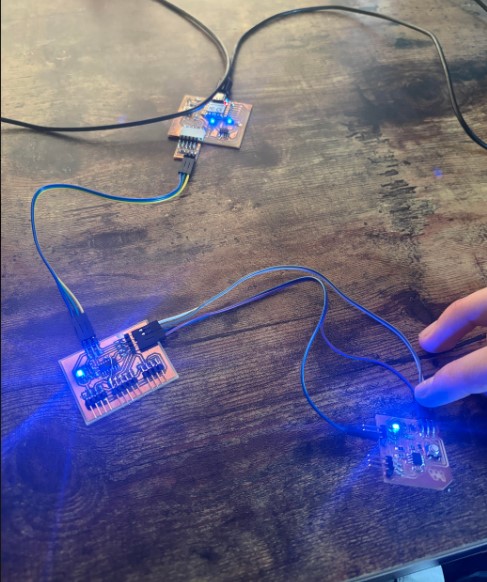
However, when I could not get this to work, I looked into the reasons that could be impededing the signal from being communicated. Since this code did not work, I will not place it here for the sake of not wasting space. The address for the communication was 0x01, which I found here that that was a reserved address, so I tried to switch them to 0x08 to see if that would allow them to work.
It ended up not working as well, so I eneded up going to ask Dr. Taylor, my local evaluator, if what I had accomplished so far was sufficient. After speaking with him, he stated that what I had accomplished with the multiple I2C devices was enough to satisfy the requirements of this week, and since this part of the board was already originally intended to be an add-on, I was fine with it ending as is.
Later Reference
I am returning to this page on a later date to state that I was able to get the I2C signal working on the group project, which is linked just below. The main issue was that there was not meant to be a shared power, and the two devices should have been plugged in independently to produce the correct results. Also, there was meant to be a shared ground.
Group Project
The group project for this week was to connect my project and my groupmate’s project and prodcue some sort of result. I once again worked with Alana Duffy, and our group site for this week can be found here.
Individual Contribution
I adapted her code through ChatGPT and changed mine based on Adrian Torres’ documentation. We used my BNO-055 sensor and her Bluetooth device to connect to each other and communicate. I documented much of the process, but the work was relatively even.
Reflection
This was a good week that helped me flesh out what I needed to do in terms of the software I needed for my final project, allowing for significant progress with the programming aspect. Finally linking these two OLEDs felt satisfying and the process ended up being very simple. Not completing the connection to the ATtiny412 was disappointing, but my other school work was ramping up and making it difficult to finish it. Overall, this week provided a great opportunity to work on my final project and didn’t involve as much pain as recent weeks.