Week 3: Computer Controlled Cutting
This week involved doing group and invidiual assignments to learn about the functions and details of the laser cutting process as well as become more versed in how to use the vinyl cutters. You can download important files here.
Requirements:
-
Group assignment:
- Characterize your lasercutter’s Focus, Power, Speed, Rate, Kerf, Joint Clearance and Types
-
Individual assignment:
- cut something on the vinylcutter
- design, lasercut, and document a parametric construction kit, accounting for the lasercutter kerf, which can be assembled in multiple ways,
- Extra credit:
- include elements that aren’t flat
References:
Vinyl Cutting
Part of this week was to create a sticker using our lab’s vinyl cutters. The tradition for our Fab Lab is that each Fab Academy student gets to place their sticker on the wall with all the previous year’s stickers. This is the sticker design that I initially chose:
Pochita from Chainsaw Man
My previous experience with vinyl cutting involved simply putting the image file into Silhouette Studio and tracing it, so I wanted to try something else this time. I placed the image into CorelDraw and did Bitmap -> outline trace -> detailed logo. I tweaked the settings a litte even though I didn’t fully understand what doing so was accomplishing, and got a vector bitmap of the design.

I placed this image into Silhouette Studio and traced it.
However, many of the lines ended up duplicated or extremely messy, so I went back into CorelDraw and tried again. I created a new bitmap by doing Bitmap -> quick trace.
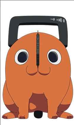
Unfortunately, this bitmap had similar looks and issues as the last one, so I attempted to trim down excess lines with the trim tool, which can remove different nodes (i.e. points) on a vector. This process took over an hour, but by the end the result had not turned out at all favorably. Because of these errors, I decided to look for a simpler piece of art, and ended up finding one.
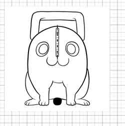
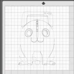
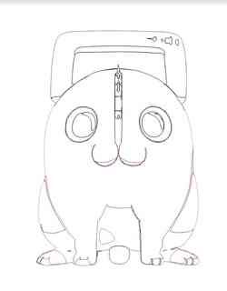
I planned to take this design and layer color onto the different parts of it even though the image itself doesn’t have color. Knowing the simplicity of the image and how Silhouette Studio worked, I successfully traced it within the software without having to create a bitmap in CorelDraw.
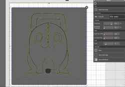
Now that the trace was done, all that was left was to cut out the different parts of the design on different colors of vinyl and layer them together
Video of part of the vinyl cutting process.
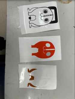
The unlayered pieces.
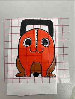
The layered sticker.
The final step was to simply place the sticker on the window of our instructor’s office, surrounded by the stickers of those who came before us.

The final product.
Laser Cutting
The laser cutting workflow for our large Eplilog Laser Cutter:
- Put the cutting material into the bed and adjust the bed height, either by auto-focus or manually
- Import SVG file into CorelDraw
- Change lines to hairline if they are being cut, keep them some other width if not
- Adjust file any other way necessary
- Go to
File -> Print -> Printto automatically open up the Epilog software, if the software did not separate vectors from rasters, do so manually with the separation tools of Epilog - Import the proper material settings and move the file to be hovered over the material
- Select
Print, go over to the screen on the laser cutter, and select the specific job that is being cut - Press the play button on the cutter
Group Assignment
The group assignment, as described above, involved discovering and understanding different aspects of laser cutting. I worked with fellow students Ryan Zhou, Evan Park, and Connor Cruz. Our group documentation can be found here.
Indiviual Contribution
My contribution to this project was the joint clearance section of it, which involved creating a Fusion360 file that had different slots of gradually less width and laser cutting that file to figure out the best slot size for cardboard spefically.
Parametric Construction Kit
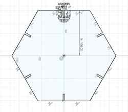
A parametric construction kit entails creating different shapes or designs that are entirely scalable based on parameters, which are essentially variables that you can change at any time. I created it in Fusion360 because, as shown in the group work above, sketches in Fusion360 could be exported into vector softwares and translated into something that the laser cutter could use. The first step of my process was to create my parameters before I could get to work on the different shapes I wanted to make. Using the knowledge from the group work and seeing that smallest hole, 3.55mm, was the best fit, I decided to make the hole parameter 3.50mm. Additionally, knowing the 1 inch roughly equaled 25mm, I made the main side/width parameter 100mm to be around 4 inches. Next, I created the depth parameter of 15mm so that I could go back and easily change how deep the slot holes were if something went wrong. Finally, I made a chamfer (also applicable to fillets) parameter in case the slots ended up not fitting very well together.

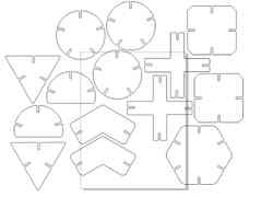
The general process of creating each shape was very similar. I would a) create a circumscribed polygon of different side numbers using the circumscribed polygon tool of Fusion360 b) sometimes modify the polygon have other features c) create the hole on the top side of the shape d) add chamfers or fillets to the hole depending on the shape type - circles had fillets, other shapes had chamfers e) revolve the hole around the shape based off the type of shape f) trim the outer side of the shape to create the actual hole. The first shape I did was a hexagon by following these steps.
I followed up by creating a triangle, a square with shortened corners, a slightly bent connection joint, a cross connecting joint, a circle with a piece sliced off, two intersecting circles, and a normal circle.
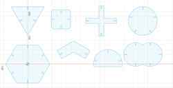
The final Fusion360 file.
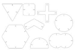
The next step was to export the file as a DXF and import it into a vector software, and I chose to use Inkscape due to it being accessible on my laptop. Once in, I shifted the objects around to fit within reasonable page parameters.

Now that I had the file, I had to do a test cut to see if the slots fit together properly. To do this, I took the SVG and put it into our school’s laser cutting software on the large Epilog machine that is described above. I imported the correct settings into the software using the downloaded library, and did my first cut. However, when I did so, the scaling became odd and the cut was done incorrectly.
I rescaled and noticed an additional issue of the some parts of the file being too big, so I resized those as well, which was made easier by the fact that the designs were parametric.

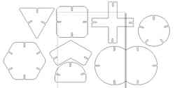
After this, I put the file back into CorelDraw and moved the pieces around to save space.
Video of the laser cutter working (sorry for the camera).
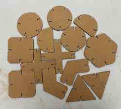
The result of cutting these pieces was this:
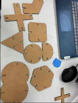
Now that each of the pieces had successfully cut out, I could cut more of each piece to create things with my kit. I copied all of the pieces, excluding the double circle due to its size, and created a new file.
I then also cut out this file.
Now that all the pieces had successfully been cut out, I decided to get a little creative with the assembly of them.
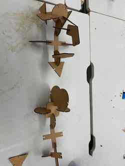
My final parametric construction kit assembly. Not sure what it is supposed to be but I think it looks cool.
Reflection
This week was very understandable due to my previous experience with similar softwares and designs. I enjoyed being able to finally add to the wall of stickers that I have been looking at for many years up until this point, and the vinyl cutting this week exposed me to layering different colors, which I had not done before. The parametric design kit was also fun, and I learned about the practical applications of being able to scale a design to meet different needs or conditions. The group project this week was initally concerning due to my uncertainty with how it worked, but by Monday I had things figured out and was able to successfully document things. The effort put in by all members was very beneficial to the process and it was nice to see everyone do their own process of creating things. My contribution helped me understand a vital part of the laser cutting process, as the connections one might needs between pieces are one of the most important parts.