Week 5: 3D Scanning & Printing
The focus of this week was the creation of 3D designs that can not be made subtractively and the use a scanning tool to scan and print out a 3D model.
All files can be found here.
Requirements
Group assignment:
- Test the design rules for your 3D printer(s).
Individual assignment:
- Design and 3D print an object (small, few cm3, limited by printer time) that could not be made subtractively
- 3D scan an object (and optionally print it)
Designing and Creating a 3D Object
Modeling
The first thing that I did in for this week was the modeling of a 3D print that could not be made subtractively. This meant that the model could not be fully constructed using tools like the milling machine, laser cutter, or any other type of manufacturing that involves taking away material from a larger substance.
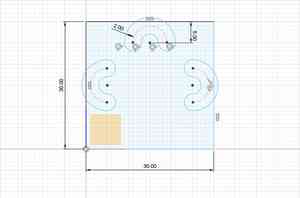
The model I did for this was a rectangular box with slots that waved up and down that created holes throughout the box. To do this, I first created a sketch that laid out design for the 3D model. I used the slot tool to create the hole, and made a pattern to create two copies of it.
Then, I created a sweep across the top of the box using a sketch on the side of box. I repeated this process again for the other two slots so that they would be swept across the other sides of the box
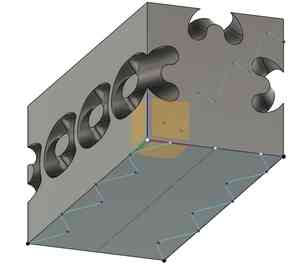
Then, I added a series of fillets across the box to smooth it out and make the several rough edges much less sharp.

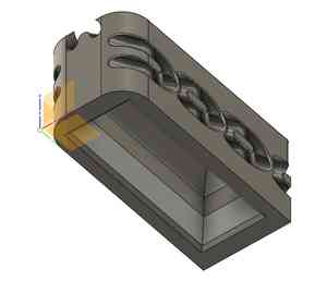
Finally, I hollowed out the bottom using fillets and chamfers to reduce the amount of material needed to print as well as the print time.
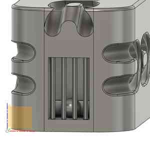
I asked one of my instructors, Mr. Durrett, if the design met the requirements for not being able to be designed with subtractive manufacturing. He explained to me that, while it would be very difficult and significantly complicated, it theoretically could be created with different subtractive machines. To rectify this, and make sure that there was no doubt to the un-subtractivity of the model, I added a small cage using some sketches and patterns, and added a ball within the cage, which would be impossible to make with other methods.
With the model having been completed, I imported the STL file into Prusa Slicer and edited the file details to have no supports, as I wanted this design to both be clean and coincide with the group project’s use of no supports on the “torture test”.

I created the gcode for the design and imported it into our school’s network of 3D printers using OctoPrint. Then, the bed of the printer was cleaned and the print job was run through the computer. At the end of the job, the print was fully created with no major issues, but it did have some support issues along the overhangs of the side slots.
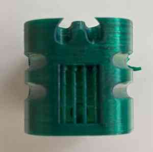
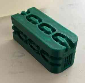
The front and home views of the final print, showing the print as a whole and the small ball within it.
The main issues encountered were the necessity of additional detail in the model and the errors with the printing of the design. The design issue was fixed by putting more effort into the creation of the model, and the support issue was unfortunately not completely rectified but still demonstrates that a rougher print might be better for the overall design than forgoing supports for the sake of a clean print.
Scanning
The scanning portion of this week was very open ended, as it involved the use of whatever scanning software that the students could figure out how to use. Many of the students used the Creality Ferret Pro 3D scanner, but since the line for the use of the software was lengthy, I decided to use the Polycam app. Initially, I had used the Qlone software, but the restrictions on the app’s use without paying a fee made me look for a better alternative. I decided to scan a pair of scissors that were sitting right next to me in the lab. The process for using the software was relatively simple, just requiring the user to take several different angles of the object. Once theimages had processed, I took the file that it gave me and used the crop feature to trim down the excess table details on the outside.
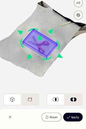
The crop tool in Polycam.

The cropped file.
Then, I exported the file as a GLB (the only free option available) and converted it to an OBJ using this website. I imported this file into Fusion360 to try and convert it into a usable format or design for printing. Using some of the help of this webpage, I first tried to convert the mesh using the prismatic option, but this repeatedly failed to load so I instead used the Faceted option. Now that the design had been converted into a surface bdody, I tried to thicken it, but this failed as the program clash. Becasue of this, I left it as a surface body.
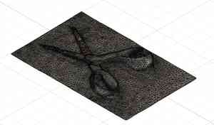
The completed file.
Group Assignment
The group assignment for this week was to test different design characteristics of 3D printer. To do this, we obtained different files to perform various types of tests, such as a “torture test” and a resin overhang test. You can find the documentation for the week here.
My contribution to the group project this week was to do the resin print. I discovered how to use the Formlabs Resin 3D printer and different aspects about how resin works.
Reflection
This week was a very light and creative task compared to what I have heard comes next. I was able to experiement with different designs and make what I what wanted to, which felt calm and simple. However, the scanning issues that I encountered in this week made deterred me away from using 3D scanning softwares, so I likely will not be using them again. Overall, this week was a nice break that provided little stress, taught me what constitutes as a 3D model that cannot be made subtractively, and gave me an introduction to scanning softwares.