Week 7: Computer Controlled Machining
The objective of this week was to design, manufacture, and assemble a large wooden creation. Options for the specific design one chooses to do were incredibly varied, with some doing intricate waffle designs, many doing funiture items, and a myriad of other potential creations being availble. Since there is so much freedom, as both my instructors and Neil emphasized, this is a popular and creative week.
Files for this week can be found here.
Requirements
Group Assignment:
-
Do your lab’s safety training.
-
Test runout, alignment, fixturing, speeds, feeds, materials, and toolpaths for your machine.
Individual Assignment:
-
Make (design+mill+assemble) something big (~meter-scale).
-
Extra credit: don’t use fasteners or glue.
-
Extra credit: include curved surfaces.
References
Definitions
Although I have had a small amount of previous experience with our lab’s ShopBot in some of the engineering courses that I have taken, there were still many ideas that remained foreign to me, so I looked into some of the different concepts and terms involved with the cutting and toolpath process. Additionally, our lab recieved the assistance of Mrs. Vaneza, a Fab instructor and co-founder of iFurniture, and her detailed explaination of different joint types helped inspire some of what I decided to do for my CNC design.
-
Feed Rate: The distance the bit travels per a singular spindle revolution; since the spindle rotates very quickly, this value is often very high
-
Speed Rate: The rpm of the spindle while cutting
-
Stepover: How much the tool overlaps with its previous passes; reduces the roughness of the surface of a cut material; (tool diameter)/2
-
Profile: A toolpath with a defined depth that cuts along a line; doesn’t remove all the material within the profile; generally used for cutting out material
-
Pocket: A tool path with a defined depths that cuts out an area; removes the material within the pocket; used for creating layers in a design
-
Outside/Inside/On-line Cut: Different ways to calculate the toolpath for the vectors of a design; dictates where the bit will cut relative to the vectors of a design
-
Upcut: A tool that has flutes moving from right to left downward; the chips/wood pieces that the tool cuts out are ejected up and out of the material, often being vacuumed by some ventalation mechanism that is on the machine; better for most general cuts since the excess material doesn’t interfere with the remaining material
-
Downcut: A tool that has flutes moving from left to right downward; the chips/wood pieces are pushed into the material or the bed; can cause
-
Chamfer: An optional step that involves using a tool with a v-bit to create angled edges
Design
For this week, I wanted to create a shelf design that is sectioned off into three main areas - two smaller shelves on the bottom and a longer but thinner shelf on the top. To do this, I started working in my prefered CAD software, Fusion 360.
Iteration One
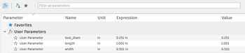
For this first iteration of my design, I began by outlining a basic idea of what I wanted the outside sides to look like. In a new sketch, I created some parameters, with one being for the width of the material, another being for the length of each hole/tab, and a final for the diameter of the tool, which could be used for outlining how dogbones will look. Each one has an additional 0.001 inches added onto in to account for tolerance so that the design doesn’t have to be perfectly cut to fit together.
Then, I created the outer side sketch.
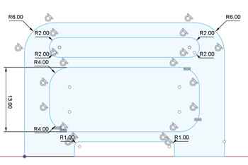
From here, a majority of the process does not require much description, as it was essentially comprised of only sketches, extruding to create 3D parts, moving the 3D parts around, and applying stylistic choices. However, a couple images will still be included
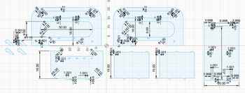
Here is what all of the sketches looked like after being created:
The two large pieces in the middle with the rounded interiors are the sides of the shelf, with the small tabs and indents being where other pieces would attach. The top two pieces are the bars than would span the shelf’s length, connecting the two sides, the middle piece, and the smaller shelves. They had two different types of joints on them, slot joints that would lock into the sides and middle, and side finger joints that would let the smaller shelves rest on top. The bottom two pieces are the small shelves, with the things on each side of both being the pieces that would be extruded to different lengths in order to either go into the bars or have part of the bar connect into it. These were particularly tough to make simply because of a small error that involved the tolerance aspect of the parameters, leading to these side bits not aligning with the rectangle they are meant to be a part of. Finally, the the rightmost piece was the top shelf that go across the top of the model and rest on the six joints on each of the standing pieces.
After all the pieces were correctly created, I turned them into 3D bodies with a width of 0.5 in, as that is the width of the material I used. I then assembled all these pieces to fit together, and the final result, with both a wood appearance and transparent appearance, is shown here:

![]()
Despite this model appearing to work for the assignment, I thought that it would not be very good structurally, so I decided to remodel parts of it.
Iteration Two
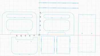
This iteration was meant to be more concise and have less confusing joints incorporated into it. Additionally, I learned from my instructor Mr. Budzichowski that I did not need to add dogbones into my Fusion design, for there was a tool in Vetric Aspire, the CNC machining software that our lab uses, that can automatically add dogbones. Most of the elements of this design remained the same, but the smaller shelves were completely scrapped and remade. I decided to have these shelves connect into the standing pieces using some slots, with each outer standing piece having two or three holes respectively, the middle standing piece having five holes, and both shelves having two slots on one side and three slots on the other.
To do this, I simply measured 10 inches from the middle of the large standing pieces and spaced out the holes accordingly and added squares at different locations. For the middle shelves, I adjusted their lengths to be able to fill the whole space between the standing pieces, and added the slots on the thinner side instead of having them on the wider sides like before. Then, after skimming through the recording for this week’s lecture (our instructors did not make us watch it already), I found an interesting point on how the whole design might still be able to fall because it might not be supported in that certain direction. To ensure that this was not an issue, I added bracers for the outer standing pieces, and added more holes so that they could fit in. This was what the final result looked like after making all of these adjustments and designs:
I then extruded all of these profiles and assembled them with the align tool to look like this, once again having both a wood version and a clear version:

![]()
Two perspectives on the final product.
Using Vetric Aspire
To create the CAM toolpaths for our lab’s ShopBot, we use Vetric Aspire, which, due to its costly fees, was limited to only being on the computers in the lab. As such, I could not operate the software over our school’s Spring Break, further contributing to the significant level of work I had to catch up on. To use Aspire, I first had to save the sketch for my shelf as a DXF, which can simply be done by right-clicking it in the Browser menu on the left and selecting the “Save as DXF” option.
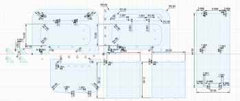
I imported this file into Aspire and began to set up the file. I defined the stock parameters to be 96”x 48”, which were dimensions that I had been unaware of up until this point. I found that my file greatly exceed the size limits of the materials, so I had to begin to plan around that fact. In the file setup menu, additional settings that were changed include turning off the offset and choosing the origin to be in the bottom left under “XY Datum Position”, making the depth of the material only .495” instead of .5” to account for descrepancies in the cutting process, and changing the “Z Zero Position” to “Machine Bed”. This last option was chosen due to the variable depth of the material, for not all of it would be consistent and some parts might bow upwards when attached to the bed of the ShopBot. Once all these settings were chosen, my file looked like the following:

As can be clearly seen, the file did not at all fit within the dimensions of the wood. Initially, I planned to just use a second piece of wood to fix this, but upon hearing the price of each indiviual wood piece to ~$60USD, I began thinking about how I could fix it. The only solution I could think of was to scale down parts of my design, so I went into Fusion360 and began to change different heights and lengths. The main things that were changed were 1. the two outside standing pieces and the middle standing piece were shortened in height 2. the smaller shelves were shortened to create a new total length in the shelf and 3. the top shelf was shortened to accomodate for this new change.
Then, using the same methods as before, I moved around the pieces mainly using the align tool and created a wood design for the shelves.
Now that I had a new sketch with dimensions that would fit the size of the wood, I brought the file back into Aspire and moved different pieces of it around. Next, under the “Edit Objects” section of the “Drawing” tab, I selected the fillets option, and I then used the software’s built in dogbone tool to create dogbones in all of the interior angles of my design. However, I found that many of the corners were not working at all when they should have been.
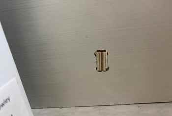
With the help of Mr. Dubick and Garret Nelson, I figured out that I need to convert most of the shapes from open vectors to closed vectors, which would allow the dogbones to be added. Once again in the “Edit Objects” section, I selected “Join Vectors”, which opened up a menu that allowed me to input a tolerance and select the different vectors I wanted to join. The tolerance allows the lines to be slighty not connected, and it was automatically set to 0.004”. Then I went back to the fillet menu after joining all the open vectors, but when I went to select the small pieces meant to support the tall standing pieces, I found that the corners were not working. I zoomed into the corners, and saw this:

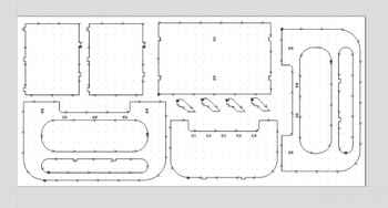
Though it does not seem like much, that slight line to the right of the longer lines was messing up the file a lot. I right-clicked the vector, which highlighting everything since it was joined, and went into the Node Edit Mode. I clicked on the small line, clicked on the dot that appeared on the right side of it, and selected “Delete Point”. I thought this had worked since the vector automatically rejoined, but the dogbone tool was still not working. I went back to the corner but was a bit more zoomed out and saw another point to the left, which I went to and also deleted. After this, the file was correctly setup up, so I added the remaining dogbones and began to start working on creating the Toolpaths. I chose the “Profile” option in the “Toolpaths” Menu so that I could create a path that would cut out each piece. I set the material width to .495” to make sure it would cut all the way through and went into the “Select…” menu for tool selection. I chose the Large Machine in the top right and selected 3/8” Compression Spiral (Onsrud 60-951) tool, for that was what my instructors reccomended.

Then, I changed the pass depth to .125”, as that seemed to be an appropriate amount for the .5” wood. I went into “Edit Passes…” and ensured that each pass were all .125”, except for the last cut being slightly less. I selected “Outside/Right” under “Machine Vectors”, and went to the tabs menu. The purpose of the tabs is to make sure that the wood can not go flying out of the bed after being cut out from the main piece, so these are crucial for ensuring safety and not letting the piece get messed up from detaching. I sparsed these out around each of the pieces, often doing four for all of the larger ones and two or three for the smaller parts. For the final step of the profile, I just clicked “Calculate”. It was now time to work on the pocket cuts for the holes where the pieces are supposed to connect. These were done as pockets instead of profiles since the tabs would have been difficult to deal with when assembling. I chose the correct vectors and had most of the settings be the same besides the tabs, as those simply don’t exist on pockets. I once again clicked “Calculate”, resulting in the software displaying the toolpaths in both 3D and on the 2D space I was working with before.
Now that the toolpaths were configured, I could simulate them if I wanted to and was now able to export this file for machining. After saving the file as a Aspire file, I imported it into the computer in the room with the CNC machine and once again made sure everything seemed correct before starting the job. While I thought that it did, there were some things that got messed up, and, for instance, the starting posistion of the board was reset to off the material, not off the machine bed. However, I did not notice this since it was correct on the file that I created. Still, with the help of Garret, mentioned above, we began the cutting process.
Cutting and Assembly
To ensure that all the choices I made were correct, I followed this workflow for our lab’s ShopBot and ShopBot software. Following the steps, I opened up the file in the software, ran an aircut and the homing procedure, and began actually cutting. Due to our lab’s safety procedures, the students were prohibbited from taking videos of the CNC machine running, but we could take a photo when it is not running.
INSERT PHOTO OF SHOPBOT
During the starting portion of the cut, I noticed that the pockets, which had been changed in the order to go first, weren’t going all the way through, so I went back into both toolpaths and changed the cut depth to .51”. The system gave me a warning, but I ignored it and reran the job. Most of the process went smoothly, but one major issue that occured was that I had accidentaly set the dimensions of the board to 98” instead of 96”, caused complications for the piece on the far right. When the system gave a warning that the piece would be an issue, many other parts had already been cut, so I couldn’t just redo the whole thing. Instead, I decided to remove all the pieces that had already been cut out in the file and just cut the ones remaining alongside the modified, which was just changed using the trim and line tools to be a bit shorter.
Now that this new file was configured properly, I ran the rest of the cut without complication. When it was done, I used a oscillating power saw to cut off the tabs. I decided not to cut them off for the interior parts yet, which ended up backfiring when I tried to transport it. The weight of these waste pieces made the tabs snap and tear off small strips of the wood, but the effect was negligible. I took every piece out and laid them out to be able to have a visual of the overall perspective.
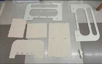
Unfortunately, something about the cut was wrong, as the joints were not connecting fully and significant space existed between the joints.
To remedy this, instead of using glue, I used shims, which are thin scraps of wood that can be placed into joints like this in order to tighten the connection. Thanks to some small pieces left behind by Dr. Taylor and Mr. Budzichowski, two of my instructors, I was to create the necessary shims.
![]()
To cut them and sand them down to the dimensions that would fit, I used our lab’s band saw and belt saw. I measured a rough distance for each shim when using the band saw, and affixed these small bits to a wooden rod using double-sided nitto tape so that they could be sanded down.
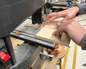

Our lab’s band saw (right) and circular saw (left) in use.
Once the shims were made to a decent size, I forced them into place using a large mallet (a process that was pretty loud). Most of the time, the shims were too large, so there were several long cycles of sanding and then testing and then sanding again to see if they would fit well enough. Additionally, the process of forcing some of the sims in made small cracks in the surface of the wood that the other wood is being inserting into (i.e. the piece touching the metal table in the below image).
![]()
Once all of the shims were inserting in, sixteen in total, the shelf was finished! Though there was some room for improvement, such as how the file could have been recut with the holes having the correct dimensions, but something like this was not done due to the individual cost of these boards.

Though there were some errors, I am very pleased with the outcome. However, seeing the size of it now made me question where I could reasonably fit it, as the width in particular seemed troublesome. As already stated, I still am glad that this project is over, since it took place during a very stressful week.
Group Project
Group Documentation for this week can be found here.
Individual Contribution
Reflection
This week had a messy start due to it taking place over our spring break and that I was informed very late into the electronics design week that I would be presenting the very next day. I was able to CNC my design first, something that was both nice but also came with inherent drawbacks of essentially being the test person for the rest of this years students. I did not have all the procedures down and couldn’t entirely learn from others, as no one else in our fab group had cut yet. The guidance I recieved from my instructors helped me get through the week and have time to create and program my board for electronics design. Overall, this was a paradoxical week, with a low stress spring break but a very tough first few days after coming back to school.