Week 12: Molding & Casting
The goal of this week was to create a mold for a casting pour. The three ways to do this in our lab included 3D printing a mold, milling out the mold, or directly resin printing the design. For the former two options, we had the choice of either creating the mold itself or creating a positive shape for a mold to be made out of. Then, a material, such as resin, though we had many more, could be poured into the mold.
The primary files for this assignment were too large for my repository, so they will not be linked here but can be found below.
Requirements
Group assignment:
- Review the safety data sheets for each of your molding and casting materials, then make and compare test casts with each of them.
- Compare printing vs. machining molds.
Individual Assignment:
-
Design a mold around the process you’ll be using, produce it with a smooth surface finish, and use it to cast parts.
-
Extra credit: use more then two mold parts.
Design
For my design, I wanted to do a topography map of one of my favorite places to go skiing: Lone Peak Mountain in Big Sky, Montana. However, over the course of creating the design, I had to remove many layers and corners to reduce complexity and increase the ability for the design to be feasible.
Design
The inital step in my design was to find a suitable map that I could convert into an image that can be worked with in Fusion360.

I found this simple design after looking on Google for a short period of time, and decided that this image would work well due to the contrast between the white background and red topography lines. I cropped this image and imported it into Gimp, where I used the “Color > Threshold” option to reduce the lines of the image down to the main ones.
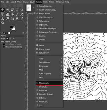
This image displays the threshold option as well as the resulting converted image of the map on the right.
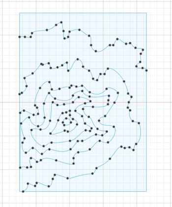
It turned out suprisingly well, so I decided to import this into Fusion360 as a canvas option to trace it. After putting the image in, I used many splines to outline some of the remaining lines and create the map. Unfortunately, due to the map being cut off on the left, that side had to be created somewhat akwardly.
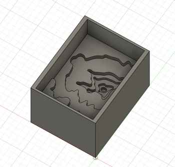
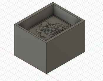
Now that I had this image, there were two steps to take next - one being to create the 3D design mold, and the other was to create the negative imprint that would be milled out on wax, our lab’s chosen material.
The positive:
The negative:
Since I had both designs, I first printed out the standard design using PrusaSlicer and our lab’s integrated network.
Manufacturing
For this step of the process, I went into Fusion360’s CAM Manufacture software to create the toolpaths for the milling job of the negative design. Throughout these steps, as previously mentioned, several design changes were made to simplify the milling job and cut out error. I followed this tutorial for knowledge about how to set up the workspace and how to start off my setup. I created a setup for the design, and in it I chose the Autodesk Generic 3-axis for the machine and selected the Z and X axes. I then defined the stock size to be that of the 3D body and clicked OK.
I created an adaptive clearing toolpath, initially with a 1/8” flat end mill but eventually I changed it to a 1/8” ball end mill, as I was worried that the 1/8” bits that our lab had were not long enough to accomodate the depth of my design. I created a second one of these toolpaths for the channel around my design, since when I tried to add it to the first toolpath, it didn’t configure properly and had an odd error. Later on, I discovered that the reason for this was that I had multiple depths turned off, but since I had already created the other toolpath, I decided to just leave it as is.
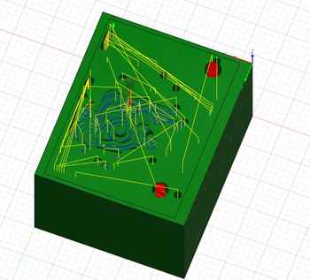
Next, I added a pocket toolpath with 1/16” ball end mill for the finishing pass, which we were required to have. During this step is when I took out the bottom-most layer of the topography map since it was causing concerns at the time with how deep the bit could go, and I adjusted the other two toolpaths accordingly. Once all the toolpaths were made, I ran a simulation to see what they would end up looking like.
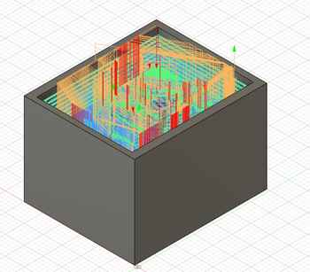
The many red marks on the left of the timeline on the bottom said “Rapid collision with stock.” I searched this up, and it seem to be a issue that would hopefully not interfere to a significant degree with the milling job. I spent a fair amount of time attempting to get rid of this error, to no avail, as even some of the errors disappeared when I would make changes to some settings that could have negative effects, many other errors would not go away. The second error on the right of the timeline said that the bit would collide with the stock, but I viewed the toolpath simulation at that point in the timeline and saw that it would be fine, especially since this was going to with the 1/16” and not the 1/8”.
I went to the Post Process menu to create the .nc files for the milling operation, and recieved an error saying “Different tools have the same tool number assigned to them. The post processor will not perform a tool change, which may mean that the wrong tool is used for an operation.” I went into my tool library, and saw that both the 1/8” tool and 1/16” had the same tool number, meaning that they were techincally under the same value, making the system default to the 1/8” since it comes first. I changed the number of th 1/16” tool to 2 instead of 1, and this fixed the issue.
Now, the designing portion of the week was done and I could get to the actual Molding and Casting.
Molding and Casting
There were three main parts to this process: the 3D print, the resin print, and the milling. The milling job would be the most complicated, since it involved three steps, instead of the other two operations only having two. These details will be explained in the individual sections.
3D Print
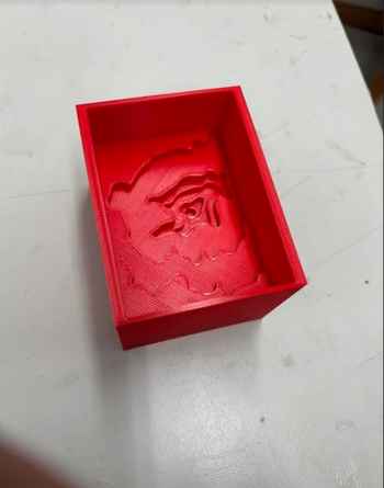
After I printed out the normal topography map on our 3D printers, a clean result was created.
Since this was a hard shell, I had to use a soft material in order to be able to take it out once it had finished. I used our lab’s Moldstar Series 15 Slow, which, according to this datasheet, is mixed in a 1-to-1 ratio. I also used mold release to make it easier to extract the casted material after it was done.

With the help of Angelina Yang, I mixed the two together, applied the mold release, and poured into the 3D print.
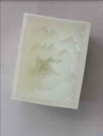
I helped Angelina pour her’s as well, and then we set these down and waited until the next day to pull them out. The one concern with this process is that we may not have stirred for long enough, as there were many tiny bubbles throughout the cast. However, the final result was still clean, and the only bad part was the bit I scratched when pulling it out.
Resin Print
A second way of creating the mold that I followed was printed the same file on resin to compare molds as well as the final results that they produce. Using the workflow discussed in my group project for week 5, I loaded my file into the Formlabs software for printing, as this specific computer had a connected already hooked up to the resin printer.

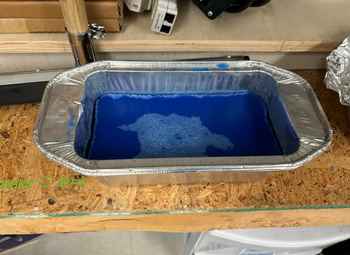
I simply printed the file out and waited for a while. The next day, I saw my print with supports and placed it into the alcohol bath to clean off the sticky resin. I also cleaned off the build plate, as per the workflow for using the resin printers.
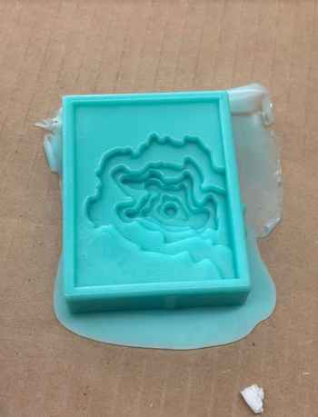
Next, I put the print in the curing machine, which uses light to make the resin bond together. After that, the creation of the resin mold was done.
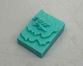
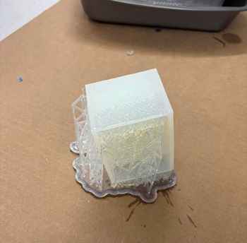
I then followed the same procedure for pouring the moldstar as above, mixing the two parts and pouring them into the resin mold. I ended up not having enough of each, but this was not a problem since I was able to fill up the necessary space.

After it hardened overnight, I took it out and noticed that it was still a bit goopy. I suspect that this had to do with improper amounts mixed on each side, but it could have also been the resin having some moisture in it.

Now that this process was done, I could continue with the milling process.
Milling
As discussed in the manufacturing section, I created a toolpath for the milling of my design. The intention was to create this design, make a mold out of that, and then cast into that mold. I first imported my file into Bantam Milling Software to make sure that everyhting was set up properly.

Additionally, the 1/8” ball nose bit that I chose was the following:

Attempt One
My first attempt to mill out of wax started with my first block of wax. While we had several machined pieces, some of my fellow students had melted down wax to create larger, wider blocks, which made it easier to scale up my project. I split this block with another student, and while I knew that the piece was uneven in many respects, I believed that it should be fine for the milling, since all the material on the top would be cut away.

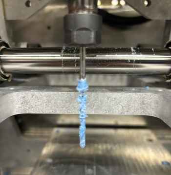
This was the block I chose, and I had made sure to press it down with Nitto tape hard and squeeze it up against the corner of the build plate. However, since the bottom was not even, the job failed. I had stepped away to do other work due to the job being over 6 hours long, as shown above, but during this duration I suspected that the piece became dislodged from the tape and was moved around. Initially, the toolpath continued to cut into part of the wax, but by the time I got there the wax was on the other side of the bed.
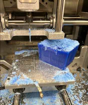
The bit had also gotten clogged by wax, which was liekly caused due to it trying to move around in wax so deep that hadn’t been cut into yet.
Since this job had entirely failed, I scrapped this piece of wax, cut it down, and melted it back to a block.
From here, I began to start my second attempt.
Attempt Two
This attempt started off with trying to cut down the wax block that I had created. I used our lab’s band saw to do this, but by mistake I had initially tried to use the smaller one that was not meant for milling such a large, non-wooden item (granted, it did say “BAND SAW” in big red letters and I was extremely tired this week due to overworking from school assignments). This ended up snapping the band of the machine, meaning it would have to be replaced. The other, larger band saw is what I tried to use next, which produced mixed results for the bottom. However, seeing these results, I opted to try and recut a different piece of wax that we had in the lab, which had a very rough bottom and sides, but I used the adjustable barrier on the band saw and cut it very evenly.
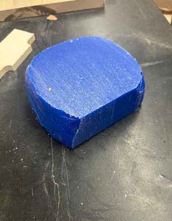
I also put this wax block into the machine after very securely securing it with Nitto tape.
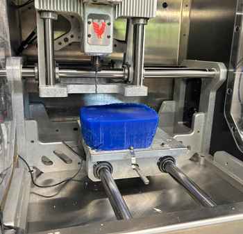
Then, I imported the file back into Bantam, and while I was unable to obtain an image of the main g-code, the finishing appeared like the following:

I ensured that all of my dimensions for the stock were correct, then I ran the file and waited for the ~4 hour operation time. After it ran, I collected much of the wax scraps into a bin for later reuse and used the vacuum machine to clean up the rest of the scraps.


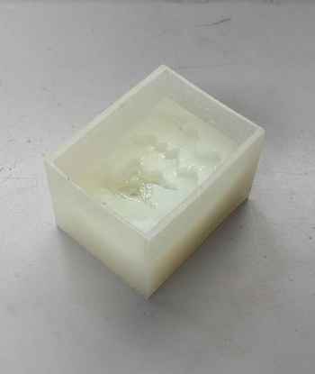
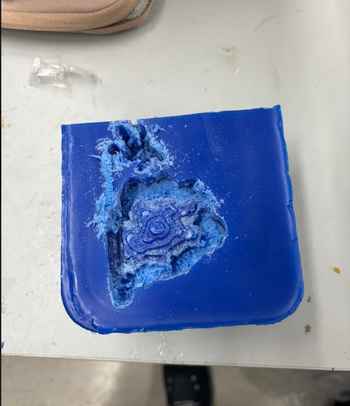
Then, once again using the moldstar procedure, I poured the mixture into the negative mold. Once this hardened, I took it out and noticed that the quality was very clean, different from how the resin print turned out.
The two parts to this mill, mentioned slightly earlier, were the roughing pass and the finishing pass. Due to the bit constraints, I had to use a 1/8” ball nose mill for both, but to classify the finishing pass as finishing, I significantly decreased the step over and speed of the bit, which thus made a much smoother final surface. The purpose of the roughing is to take out as much material as possible with little consideration for the surface, whereas the finsihing only moves across the final surface after the material has been taken out in order to make it smooth.
For the next step, since this was a soft mold, I had to use a material that would end up hard. The primary hardened casting material we had in the lab was Smooth-On Task 8, and the the datasheet can be found here.
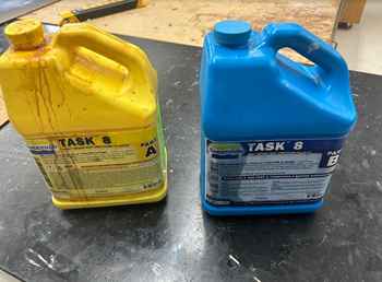
I mixed them, once again alongside Angelina, in a 1-to-1 ratio and poured it into my mold. I had seen earlier with a fellow student’s that the material would solidify very rapidly once the reaction started, but by the time that I noticed it was changing and pulled my phone out, it had already changed a fair amount.
Once it had fully solidified, which only took roughly 20 minutes and produced a significant amount of heat, the process was done.
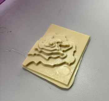
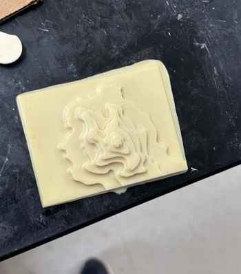
This product was clean and well done, which was a very welcome change compared to the resin.
Group Project
The group project this week was to review the datasheets for our molding and casting materials, as well as compare the casts and molds and their respective procedures. I worked with Alana Duffy for this week, and our group site can be found here.
Individual Contribution
My contribution to this project was the analyzation of the datasheets and their entire documentation. I found the necessary information from both datasheets and placed them onto the group site, as well as compared the end results of my different casts.
Refelction
This week was a very long a tedious one, dragged down by the annoying process of creating the toolpath and the residual effects of machine week still impacting my work slightly. Though it was meant to be expressive and creative, I ended up not enjoying this week very much due to the tedium of the milling and manufacturing process. While I’m glad I got do make something somewhat creative that I might be able to give to my mother for mother’s day, it was still arduous and, as already said, annoying. Overall, this was a dragged-on week that was, by the end, not enjoyable.