3D Modeling and Planning
IGNORE PAGE, GO TO MAIN
For this section of my final project, I want to focus on planning out the general shape of the project as well as look into different sensors or components I might use.
Planning
The planning portion of this document includes creating a very rough idea at the start of Fab Academy, creating a bill of materials, a Gantt Chart for time planning, and a lucid chart for mapping out the entire project in a system diagram.
Early Sketching
For myself, I found it easier to map out my ideas on paper rather than typing them all out individually, as it helps in being more creative with brainstorming and writing. I drew out some basic ideas and small sketches on a piece of paper to get an initial understanding of what I want to do with this project.
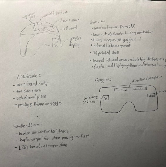
Going section by section for this, the top left shows a side-ish profile of the helmet which contains the general shape of the helmet, the electronics stored within, the goggles display, and a small supporting piece that may be part of the effort to make the top detachable. To the right of that, under “Overview”, I lay out a few basic idea that I want to do for the project. This includes a CNC wooden frame for the foundational elements of the helmet, googles made of some transparent material, laser cut electronics holders that could help keep the wires together as they move from the PCB board to the goggles, the components being within the helmet, several 3D prints to create curved surfaces that might connect to most of the helmet to smooth it out, and the several sensors that may be included. So far, I know that I want to have a spedometer, an indicator towards the angle of the hill that is being skied on (possibly an inclinometer), and some form of compass on the top of the goggles. Some of these may be able to be incorporated using this 9-axis MEMS Motion Sensor, which includes a gyroscope, an accelerometer, and a compass, each of which could read and produce different values for my project. I do worry that using some simple LCD screens to display this information will be too unsophisticated, so I’ll definitely try to do something more complicated for that. Below this overview shows the current idea I have for the goggles, with the positions of the different sensors. One thing I am unsure of currently, as is additionally shown to the left of the goggles on the paper, is how I will connect the goggles to the rest of the helmet in a way that is not just a glue or some other less than ideal method. As the goggles are the main form of output that I plan to have, they will be critical to orient and get right. The final section of this paper is the “Possible Add-Ons” part, which shows some other things that I might want to include based on random ideas or the suggestions of some others, like how Mr. Dubick, my instructor, suggested a haptic sensor of some sort.
I am very excited to begin working on this, as I believe that it will hopefully be able to prosper into something well designed and aesthetically pleasing.
Some other areas I looked at were previous year’s final projects that incorporated helmets. I took some inspiration from Miriam Choi’s Final Project and also viewed Jasmine Rubitovitz’s Final Project to find some more references about what I wanted mine to be most like.
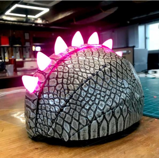
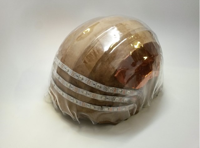
Miriam Choi’s (top) and Jasmie Rubitovitz’s (bottom) final projects
I thought that the motion sensor aspect of both was well done, so I wanted to represent that idea through the spedometer. Additionally, the designs that these people used helped me get a better idea of what my helmet may come to look like. I realized that my helmet will likely be extremely bulky due to the height required for the electronics housing. Once again, I am looking forward to working on this more in the future and developing a more formative idea of what the final project will look like.
BOM
For my bill of materials (BOM), I went into Google Sheets and began to list the electronics components, the building materials, and various other items such as a power supply to make the program able to run autonomously while being on someone’s head. From my Output Devices work and documentation, I knew that I would need a chip with more storage in order to be able to run the OLED code that I wanted to as well as any other meaningful programs, namely the sensor I wanted to incorporate.
Additionally, I realized that I needed to have a second OLED screen to display the magnometer readings on this screen as if it is a compass in the top-center of the goggles. Since there were going to be more than one device on the I2C ports, I thought about trying to use a I2C multiplexer, but decided that I only truly needed to change the address I am sending data to while programming. This is due to the addresses on the OLED screens, but those details are explained in separate sections of my Final Project documnetation. I figured out, based on Neil’s reccomendation, that I was going to use th BNO-055 Adafruit sensor instead of the preivous MPU-9250.
After finding some links for various thing that I planned to use, I put it all into the Google Sheet, which (hopefully) can be accessed here.

One of my current primary concerns was if the ATtiny1614 would have enough storage to be able to run both the OLED program and the the BNO-055 library. Another thing I did not know yet was the details of the acryllic we had, as the quantity and width were unknown.
System Diagram and Gantt Chart
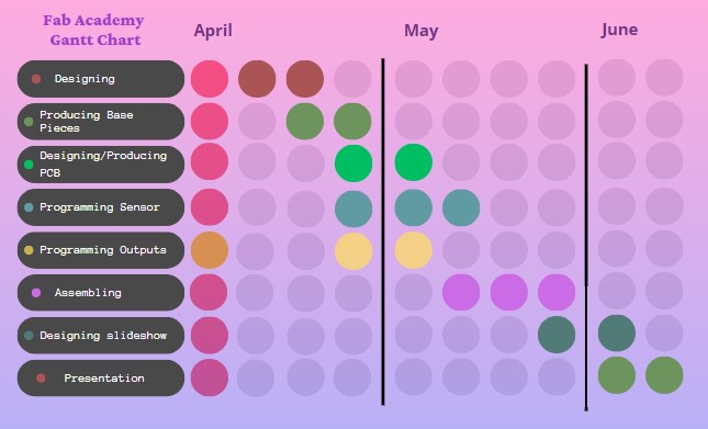
The next step was to create a Gantt Chart. A Gantt Chart is a type of chart that displays different tasks on one axis and the time periods that these tasks will be accomplished over on the other axis. Some charts can use bars to show an extent of time, others additionally have arrows to relate the tasks togehter, but for myself, I used the different remaining weeks of the year to display to the time blocks that each task would be grouped into.
The template that I used for my chart can be found here, and this site was reccomended to me by Angelina Yang . The months are displayed at the top of the chart, and each month is broken up into four circles, one for each week. Then, I color coded each week, marking finished weeks/progress as a reddish-orange and coloring weeks that have passed in a gradient of pink to purple.
Now that I had a Gantt Chart, I created a system diagram. To create my system diagram, I went onto Lucid Charts to create a flowchart that would include the following:
-
The different parts that would be manufactured in pink.
-
The general performance goals in orange.
-
Potential future integrations in blue.
This design was pretty fun and creative to make, and there is definitely more room to add to or customize this design.

Since everthing was laid out for the project, I made a list of tasks that still had to be completed.
-
Finish the 3D model aspects of helmet in Fusion 360 - April 21
-
Finish the CNC aspects of helmet in Fusion 360 - April 21
-
Print out 3D parts and machine the wooden parts - April 23
-
Combine 3D and CNC through sanding or reprinting - April 26
-
Program sensor and put sensor data onto one OLED - April 16
-
Program two OLEDs with the sensor data
-
Create board for the sensor and integrate electronic components
-
Troubleshoot since this is bound to have some issues
-
Merge helmet with electronics and place wire holders along the outside
-
Add power supply once helmet has display
-
Disconnect the helmet from computer and power cord, make it run autonomously
Early 3D Modeling
As shown in my week 2 documentation, I created a very rough model of what I wanted to overall helmet to appear like. Due to my limited CAD skills, this design is very limited in scope, but I do intend to create a more thorough and realistic model very soon. This was the rough model that I created during week 2:
The primary point of this model is that it is meant to show a very rudimentary representation of the potential shape of the helmet, as well as illustrate the place where electronics will be housed in the interior of the helmet. As just said, a better model is in the early stages of creation, as I was still figuring out what I wanted to do for the googles.
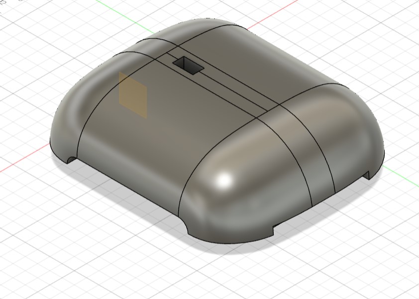
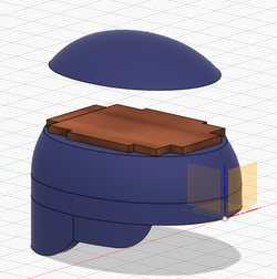
Middle 3D Modeling
Throughout the program, I have intermittently worked on the overall 3D model for my design. In this second iteration, I wanted to create a more accurate model. The first steps of the process involved creating the base of the helmet, which would have most of the design based around it. This would be a CNC machined part, as it was intended to be flat and large. Initially, I parametrically design this around estimated values of the size of my head, but when these values turned out to be much smaller, I had to readjust the overall design. The actual values of my head shape were around 8” x 6”.

Also part of the initial process was the cap, which was made using perpendicular sketches, the sweep tool, and some tangent splines. It took a fair bit to figure out how to properly curve the shape, but eventually it turned out fairly well.