Week 6: Embedded Programming
The goal of this week was to use the programmer board created in Week 4 to program a microcontroller. This involved milling out a new board, soldering on the proper components, connecting it to the RP2040, and programming it. I worked with Ryan Zhou and David Vaughn directly in my group, and with Richard Shan and Alana Duffy in another group. The five of us worked to program the SAMD11CA14 chip in order to get a simple LED to work.
Files for this week can be downloaded here.
Requirements:
Group Assignment:
-
Browse the data sheet for your microcontroller.
-
Compare the performance and development workflows for other architectures.
Individual Assignment:
-
Write a program for a microcontroller development board tha tyou made to interact with local input and/or output devices
-
Extra credit: connect external componenets to the board
-
Extra credit: use different languages and/or development environments
References:
Milling
First Board
Note: Before following these steps, note that this board did not end up working.
The first step in this week was highly confusing, as there was no explicit direction to take the first step towards. We looked at the QuenTorres Documentation to get a general gist of what we were meant to do, and found a project called the SAMDino. While not discussed in any detail in the QT documentation, it linked me to here, where there was a .brd file for milling the board. When we imported this file, however, we noticed that the pads for several of the points which were meant to be soldered were missing, so we decided to try a different approach. This is where I learned how to use Mods, a program built by MIT that allows for the conversion of PNG files to NC files, which are mill-able. The workflow for it, at least for Bantam Milling Software, is:
-
Open Mods
-
Right-click and select “Programs”, then select “Open Program”
-
Scroll to “Othermill-Bantam Tools” and select “PCB”
-
In the top left box, click “Select PNG file” and open the desired PNG
-
Select the specific settings (i.e. traces or outline) of the milling job in “Set othermill defaults”, which should be below the previous box
-
Over to the right, turn the toggle of for “Save File”. This should automatically save the file after the next step.
-
Click “Calculate” in the center, and if all settings are correct, load that file into the milling software.

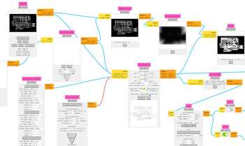
The mods website page appearance for the outline(top/left) and the traces(bottom/right) of the SAMDino board.
I took this file and imported it into Bantam, with the g-code for it coming out like this:

Then, following a similar procedure to the one detailed in week 4, I milled the file with the help of Ryan Zhou.
Despite the success in milling this, I then figured out that there was a much simpler board that we could mill and solder that was posted on the schedule for this week. This was the basic blink board, viewable in the ATSAMD11C section of this week’s schedule.
Second Board
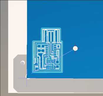
Now that we had a better board to work with, my group created the file using Mods, with 1/64” being selected for the traces and 1/32” for the outline. Once configured correctly, the files looked like this:
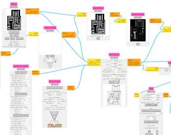
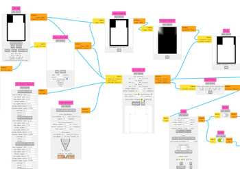
Screenshots of the traces (left) and outline (right).
Then, with these files, we went back into the Bantam milling software and configured the settings like before with a slight offset to make sure that the job did not collide with the frame of the bed. The g-code was then created.
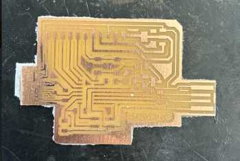
We milled this file without complication.

After this, we began to solder on the components based off these two images, one being the schematic and the other being the photo provided by Neil:
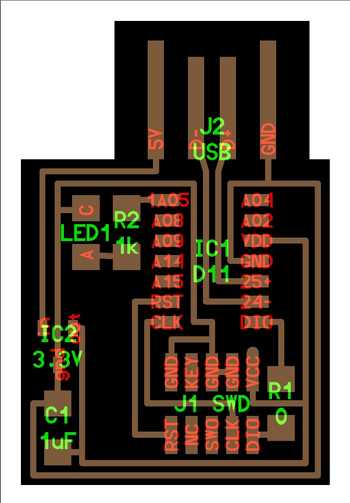
The components shown in these images are as follows:
| Component | Quantity |
|---|---|
| SAMD11CA14 Chip | 1 |
| Blue LED | 1 |
| 1K Ohm Resistor | 1 |
| 0 Ohm Resistor | 1 |
| 3.3V Voltage Regulator | 1 |
| 1 uF Capacitor | 1 |
| 10POS 2x5 Header Connector pins | 1 |
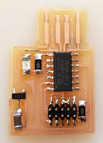
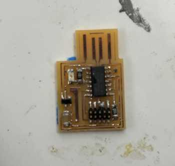
We noticed that we did not initially have the necessary 3.3V Voltage Regulator, so I took one off of an old board and attached it to my own, leading to the final result looking like this:
 {: width=”250”}
With the board completed, we could move on to the programming part of this.
Programming the SAMD11C
The SAMD11C is microcontroller used in programming that has a variety of different uses and is suitable for low-power and small-size embedded systems.

The pinouts of the SAMD11C, accessiblehere.
In order to program the SAMD11C, I first had to flash the bootloader on the RP2040 that was already there. There were several methods to do this, and I looked at the QuenTorres Documentation on how to do this.
The first place I picked up was on the section titled “How to use as a programmer.” With myself focusing on getting the board set up first, I scrolled down and saw a mention of edbg, and since I did not know what this was, I looked it up. This website described it as “an onboard debugger for kits with Atmel devices,” meaning that it allows a user to debug their device without having to go to an external source.
I followed this path of links, starting from the QT documentation: [QT link](https://github.com/ataradov/edbg) > [edbg link](https://taradov.com/bin/edbg/). I installed the most recent option, but when this did not appear do anything, I decided to look further into the documentation (Note: best to look ahead before going down a series of links).
It listed an alternative option of using the Fab SAM core with its built-in edbg functionality. I went to this explaination, which was listed on the QT documentation, and copied the board manager link provided into File > Preferences > Additional Boards Manager URLs. The board link given was: https://raw.githubusercontent.com/qbolsee/ArduinoCore-fab-sam/master/json/package_Fab_SAM_index.json. Once this was installed, I went to Tools > Board > Fab SAM core for arduino > Generic D11C14A.
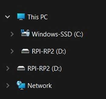
Now that the setup was done for getting the correct board, I went to get the bootloader configured. With the RP2040 board being plugged in, I held the “B” button and pressed “R”. This exposes the flash drive so that files can be placed onto it, so I went into my file explorer and saw that the RP2040 had showed up at the bottom. Now that it showed up there, I copied the uf2 file on the QT documentation into there, and it automatically closed once the file loaded.
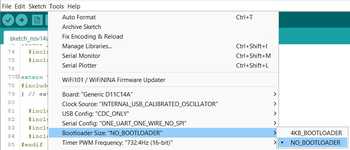
I went back into the Arduino IDE software in order to also work on the bootloader. In Tools > Bootloader Size I selected “NO BOOTLOADER”.
I ran a basic blink code to see if it worked, and got an error.
After this point, I went off trying to look for a solution to this error for many hours, skimming different documentation and forums without finding a concrete soluton. I checked this week’s schedule to try and get an idea of what to do, I clicked on a debuging video to attempt to find a solution. I noticed at the top of this video that the version was 2.3.2, which was different from the version that I was currently on. I had been on 1.18.19, as 1.18 versions have compatibility with JTAG, an integrated circuit testing method that allows for on-chip instrumentation and is widely used. I changed my version by opening Arduino in the later version which I had alread used in Week 4.
When I ran another basic blink code after installing the same board library and changing the settings back, I recieved the same error. I tried changing the “Bootloader Size” option back to “4KB_BOOTLOADER”, and recieved a new error that said no device was detected at the port I was trying to use.
After taking a break, I recieved the assistance of Richard Shan. He showed me how to run edbg in Powershell, as my previous attempts had been a misunderstanding of how it worked. After downloading the correct file for flashing the SAMD chip here I ran .\edbg-windows-r61.exe -ebpv -t samd11 -f .\sam_ba_Generic_D11C14A_SAMD11C14A (1).bin in Windows Powershell. “.\edbg-windows-r61.exe” tells the terminal that the exectuable file is in the current directory, which was the user folder for my account, “-t samd11” tells the terminal the target is a samd11 board, and “-f \sam_ba_Generic_D11C14A_SAMD11C14A (1).bin” specifies the file to be loaded onto the programmer. When I ran the command I got this error:

Mr. Durret told me to check the continuity of the SWD cord to see if there was any incorrect connections. Using it, I discovered that the NC and CLK pins (reference schematic above) were connected. I decided to remill the board and add the same pieces as shown above. While I was in the process of doing this, Mr. Dubick informed us that those doing the SAMD did not have to program it through the RP2040, and just had to turn it on via a USB connection to our own computer. This choice was made in part because of the limited documentation about using a Xiao RP2040 to program the SAMD. Because of this new simplicity, I worked with other students to make the SAM blink.
The difficult parts that remained were to find a female USB cord that could connect to the USB part of the SAMD blink board that we had created, flash the board, and to debug the chip.
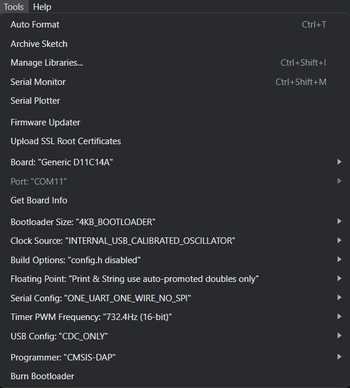
After finding this cable and plugging it into my computer, I used the previous settings I had found while initially trying to program the SAMD while changing some other, but I know the pain of not knowing which specific settings are supposed to be selected, so they are shown here for full clarity:
Then, with Windows Powershell opened and the Downloads directory opened, I plugged in the RP2040 and ran a command that I used earlier, tweaking it to look like this: .\edbg-windows-r61.exe -e -b -p -v -t samd11 -f .\sam_ba_Generic_D11C14A_SAMD11C14A.bin. This first opens the .exe file downloaded from the edbg binaries page, “-e” to erase the previous flash memory, “-b” to set the baud rate so the communcation rates across the channel between the computer and chip are equal, “-p” to specify the port, “-v” to create a verbose output that helps show the process working, “-t samd11” to indicate the board that will be debugged, and “-f .\sam_ba_Generic_D11C14A_SAMD11C14A” to flash the board using the .bin file. This was the output:
PS C:\Users\lando\Downloads> .\edbg-windows-r61.exe -e -b -p -v -t samd11 -f .\sam_ba_Generic_D11C14A_SAMD11C14A.bin
Debugger: ARM CMSIS-DAP 1093000031387d241239333437353533a5a5a5a597969906 1.10 (S)
Clock frequency: 16.0 MHz
Target: SAM D11C14A (Rev B)
Erasing...  done.
Programming................... done.
Verification................... done.
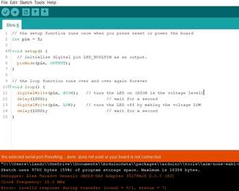
Now that the board had been debugged, I ran the following code:
// the setup function runs once when you press reset or power the board
int pin = 5;

void setup() {
  // initialize digital pin LED_BUILTIN as an output.
  pinMode(pin, OUTPUT);
}

// the loop function runs over and over again forever
void loop() {
  digitalWrite(pin, HIGH);   // turn the LED on (HIGH is the voltage level)
  delay(1000);                       // wait for a second
  digitalWrite(pin, LOW);    // turn the LED off by making the voltage LOW
  delay(1000);                       // wait for a second
}
I chose to do pin 5 because, as shown by comparing the pinouts of the SAMD11C to the blink board that was created, pin 5 was the pinout that connected to the LED. Even though it was analog, I believed it would still work as an output due to the nature of the SAMD11 chips. After running the code, I received a long message within Arduino IDE.
Atmel SMART device 0x10030006 found
Device       : ATSAMD11C14A
Chip ID      : 10030006
Version      : v2.0 Nov 22 2017 12:56:25
Address      : 4096
Pages        : 192
Page Size    : 64 bytes
Total Size   : 12KB
Planes       : 1
Lock Regions : 16
Locked       : none
Security     : false
Boot Flash   : true
BOD          : true
BOR          : true
Erase flash
done in 2.048 seconds

Write 10128 bytes to flash (159 pages)

[                              ] 0% (0/159 pages)
[==                            ] 9% (15/159 pages)
[=====                         ] 18% (30/159 pages)
[========                      ] 28% (45/159 pages)
[===========                   ] 37% (60/159 pages)
[==============                ] 47% (75/159 pages)
[================              ] 56% (90/159 pages)
[===================           ] 66% (105/159 pages)
[======================        ] 75% (120/159 pages)
[=========================     ] 84% (135/159 pages)
[============================  ] 94% (150/159 pages)
[==============================] 100% (159/159 pages)
done in 23.886 seconds

Verify 10128 bytes of flash

[                              ] 0% (0/159 pages)
[==                            ] 9% (15/159 pages)
[=====                         ] 18% (30/159 pages)
[========                      ] 28% (45/159 pages)
[===========                   ] 37% (60/159 pages)
[==============                ] 47% (75/159 pages)
[================              ] 56% (90/159 pages)
[===================           ] 66% (105/159 pages)
[======================        ] 75% (120/159 pages)
[=========================     ] 84% (135/159 pages)
[============================  ] 94% (150/159 pages)
[==============================] 100% (159/159 pages)
Verify successful
done in 0.096 seconds
CPU reset.
These lines indicated that the code ahd successfully gone through, and when I checked the board, it was blinking! This was a major relief because of how long it took to get to this stage.
Video of the SAMD11C blinking (in frame only at the beginning sadly).
Programming the ATtiny412 with QuenTorres
Mr. Dubick wanted everyone in our Fab class to program both boards, but he allowed the reuse of boards that other groups had created. With the very permission of Angelina Yang, I took her board and used it to program the ATtiny412. The primary aspects of the ATtiny board(s) that she created involve the board itself, with the chip, an LED, and a resistor, a UPDI connector board, and jumper cables to connect them.
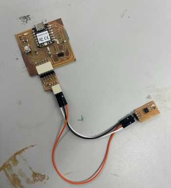
Since the entire board was set up by her, I recommend viewing her and other’s documentation to be able to understand the specifics of the connections, components, usage of JTAG and UPDI, and various other important details of the ATtiny. In order to program the board, it first has to be flashed with the instructions shown above using the uf2 file. Then, the megaTinyCore has to be installed (found here) through File > Preferences on an Arduino version that is within 1.18, with the more specific version not mattering to the same extent but still having different impacts based on the programming system that one is using. From the Tools menu, select the correct board, port, and, in the Programmer subsection, select any of the options that have “SerialUPDI”.
Once this process was done, I viewed this pinout menu from SheekGeek to try and know what pin to put in the code.
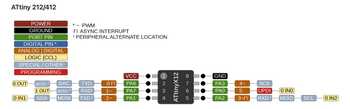
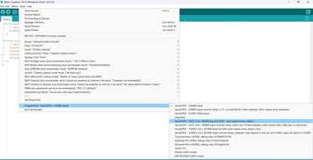
I initially tried to do pin 7, as this was what the image showed to be corresponding with the pin the LED was connected to, but when this did not work, I chose pin 4 instead due to the key on the left saying that pin 4 was the digital/analog pin. When I tried this, I got a very large set of red text in Arduino IDE, which worried me for a moment, but then I saw that the LED was blinking and infered that this text meant that the code had worked.
Text in Arduino IDE.
Video of the LED blinking.
Basic Programming
Another part of this week was to program our RP2040 to do a very basic system of outputs when it recieves an input. This is already partially documented in week 4, but I did some more in this week to add onto the programming side of the base RP2040. Since the button on the board was the only functioning input that I believed I could use, I decided to code a basic program that, on a button press, would display in the Serial Monitor some text. This is the code I used:
int buttonState = 0;

void setup() {
  pinMode(27, INPUT);
  Serial.begin(9600);
}

void loop() {
  buttonState = digitalRead(27); // sets the input from the button to either High or Low
  if (buttonState == HIGH) { // checks if the button state is HIGH/on/pressed
    Serial.println("Button is pressed.");
    delay(500);

    // LEDs are kept off when the button is not being pressed
  }
  else {
    Serial.println("Button is not being pressed.");
    delay(1000);
  }

}
The only issue I encountered were trying to get the “Serial.println()” to work, but this was a simple fix by just looking up how it worked. I also used a short delay() so that the serial monitor wouldn’t be flooded with outputs.
The monitor outputting text whenever the button is pressed.
Bare Metal Programming the SAMD11C
A final assignment that Mr. Dubick wanted us to do was to program the SAMD11C using bare metal programming. Bare metal programming is a type of programming that invovles directly referencing aspects of the chip through low-level coding that strips away the simple interface of IDE’s like Arudino. It operates similar some other firmware in how it connects to the hardware of the chip, as the system behavior itself is controlled, rather than more surface level aspects being translated into executable code later on. Some benefits include speed, scalability, and its technical simplicity.
An example of how bare metal code is masked in Arduino IDE is shown by right-clicking on a built-in function, such as “pinMode()”, and selecting “Go to Definition”. This shows the real code behind these functions, with registers, Bitwise operators, and other low level aspects being everywhere. With pinMode(), which initializes a pin to take an input or output, as an example, I went to the bare metal definition of the code and found over 100 lines of code for what normally seems like a very simple function.
To use bare metal, I modified my SAMD11C code to reference registers of the memory of the chip, which circumvents the need to use these built-in functions that take up a significant amount of space. I started by following this video to get a general understanding of how it worked. The video explained registers, which could be used as a binary string to turn different pins on and off and have different names based off which pins you are trying to control. For example, PORTD on an Arduino UNO would control pins 1-7. It also explained some differences in labelling pins, with pin 8 being sometimes called “PD8” in the case of the Arduino UNO.
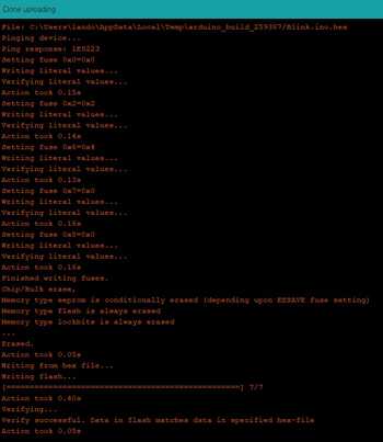
To start trying to program, I first ran the code that had been provided in the blink.ino file within the same area as the file for the SAMD11C board that was milled.
// hello.D11C.blink.ino
//
// SAMD11C LED blink hello-world
//
// Neil Gershenfeld 11/29/19
//
// This work may be reproduced, modified, distributed,
// performed, and displayed for any purpose. Copyright is
// retained and must be preserved. The work is provided
// as is; no warranty is provided, and users accept all
// liability.
//

#define LED (1 << 5) // define LED ping

void setup() {
   SYSCTRL->OSC8M.bit.PRESC = 0; // set OSC8M clock prescaler to 1
   REG_PORT_DIR0 |= LED; // set LED pin to output
   }

void loop() {
   REG_PORT_OUT0 |= LED; // turn on LED
   delay(100); // delay
   REG_PORT_OUT0 &= ~LED; // turn off LED
   delay(100); // delay
   }
When it went through, it successfully was able to run and blink the code, but it still took up 9780 bytes, which Arduino IDE said took up 80% of the storage area. This was likely due to the delay() function, which was built-in and not bare metal yet.
Despite this code working, I still was unsure about how it exactely worked, so I decided to look into more resources about what different parts of this meant. I viewed Richard Shan’ and Adam Stone’s documentation to try and learn more, and, with additional help from Richard directly, I was able to rewrite the code to try and make it more streamlined. In order to do this, I used the PORT register, with DIRSET to set the LED as an out put and OUTGL to turn the LED on. I then used OSC8M to initiate the oscilator for a for loop, and I combined the ideas of Richard and the video I watched previous to make a delay timer. I used 500,000 as the value for the 8Mhz clock, as I had seen Richard’s code have a larger value and wanted to make mine run faster.
void setup() {
    OSC8M |= 0x1; // Set OSC8M clock prescaler to 1
    PORT_DIRSET = (1 << 5); // Set LED pin to output
}

void loop() {
    PORT_OUTTGL = (1 << 5); // Toggle LED state
    for (volatile unsigned long i = 0; i < 500000; i++) {

    }
}
Video of the LED on the SAMD board blinking with bare metal programming.
Group Project
The group project for this week was to showcase the design workflow for the creation of the SAMD11CA14 board and to scan through the data sheet for the SAMD chips, writing down major aspects of the board. The design workflow is roughly a reiterated version of what appears on our individual websites, but more streamlined and less personalized to the documentation mannerisms of each person. The documentation can be found here
Reflection
This week was by far the toughest and most confusing yet. The initial slow pace of our group and confusion involved with creating the board led to significant time being wasted and much frustration. Additionally, the sudden additionof doing ATtiny and bare metal programming make the hours for this week incredibly intensive. However, I have been told that this is one of the most vital weeks for most of Fab, so I am glad that I was able to get through it and that I have attained some important knowledge involved with programming.
The stress involved with the workload for this week was very high, which combined itself untimely with personal/familial difficulties, furthering the toughness of this week. Overall, I would say that this week is an incredibly valuable one and I hope that what I have been able to do with the SAMD11C will help future Fab Students.