Week 10: Machine/Mechanical Design
The objective of this week is to work with a group of other students to try to create a machine that incorporates mechancial, electronic, and programming aspects. Since the nature of this week was to work with a group, the individual and group assignments are merged. There exists a large amount of freedom with what people choose to make, the approach they decide upon, and the purpose of their machine, leading to both more creativity and difficulty.
Requirements
Assignment
-
Design a machine that includes mechanism + actuation + automation + application.
-
Build the mechanical parts and operate it manually.
-
Document the group project and your individual contribution.
-
Actuate and automate your machine
Designing & Planning
For this project, I worked with Collin Kanofsky and Ryan Zhou. For further documentation and an explanation of the overall process instead of my individual contribution, vist our group site.
During this phase of the project, we tried to map out the general idea of what machine we wanted to create. After iterating through a few concepts, such as an automatic trash bag closer/remover/placer, a machine that bends solid wires into different shapes, and an automated soldering machine, we decided upon a machine that can create multiple long wires in bulk. The overall idea behind this project is that the machine would be comprised of several motors, a wooden frame, 3D printed corner pieces with heat set inserts to hold them to the frame, 3D printed channels for the wire, and 3D printed gears. We eventually landed on the name Cable Crafter.
After some rough sketching on a whiteboard, we created the following basic diagram:

In the center of this diagram is an illustration of the main mechanism. The plan was:
-
A spool of wire would be grabbed by gears which are connected to the first stepper motor.
-
The first motor would push the wire a to the position for it to be stripped.
-
A second motor moves the wire stripper & cutter tool into position.
-
A third motor makes the wire stripper close.
-
The first motor moves the wire back to strip it.
-
The third motor opens the wire cutters.
-
The second motor moves the tool back.
-
The first motor moves the wire until it is grabbed by gears that are connected to a fourth motor.
-
The fourth motor moves it to the correct length to be cut.
-
The same process for stripping as above occurs, instead having one more movement of the second third motor for cutting.
-
The fourth motor moves the wire out of the machine.
With this rough idea and the rough sketches, we started work on the 3D modeling and motor programming. Due to Collin and Ryan having more expertise and their prefered CAD software being OnShape, I did not participate much in the 3D modeling side of the project. While I did try to print a few pieces out, this was the area of this project where I did the least. Regardless, the files are shown, but will not explicitly be downloadable due to their size.
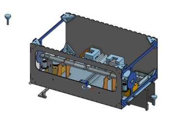
Some notes about this design is that the bottom is not configured entirely correct, the top is not included in the model, and there is meant to be a hole for viewing on one of the sides that did not get translated over when importing from OnShape into Fusion360. As can be see in this model, there will be several thin pieces dedicated to holding up the v-channels, eight corner pieces, a spool holder, a gantry system, a bed for the Arduino Uno, two stepper motors for moving the wire back and forth, another motor for moving the gantry system using a belt, and a final motor for closing the wire cutter. Besides this 3D model, shown below is the file in OnShape.
This design is missing several crucial aspects that will end up being a part of the final result, such as the wire stripper itself, the OLED components, and the rotary encoder. Nevertheless, now that we had this model, which would be added to later on by my group members, Collin and I started working on programming the motors.
Programming
To start out with programming the stepper motors, we used a CNC sheild that was compatible with the Arduino UNO, our main board for this project. Alongisde the sheild, four stepper drivers were used to turn the sheild into something specifically for stepper motors.
![]()
While programming, we looked at this comprehsive tutorial from How To Mechatronics and this guide for the pins and various tips.
As stated on our group documentation, Collin initially went through many iterations of code to try and get the motor to work before finally switching out his hardware and creating a working motor. The code that he ended finding for testing purposes was found on this Youtube video, which showed how to do the basic system of programming through the CNC Shield. In this code, 200 steps were a full rotation, so we did (200 steps)/2π (circumference of our gear), which equaled roughly 31.831. From this starting point, we used our limited knowledge of coding in C++ to try and get the rest of the program to work. Our function for the motors consisted of a boolean value to determine the rotation, a speed value for the speed of the motor, with a larger value being a slower motor, and a distance value that would determine how far the motor would rotate. We did a simple for loop to get the steps, with the variable for distance being incorporated into the loop. After getting all this programming done, we were now able to rotate the motor a custom amount along the circumference of the gear, which was a positive start.
200/(2π) = 31.83098892
Then, using the example code from the video, I used Arduino IDE to initialize the correct pins, comment out unnecessary code, and write a function for the amount/length of rotation, speed, and direction. After completion, it looked like the following:
// CNC Shield Stepper  Control Demo
// Superb Tech
// www.youtube.com/superbtech

const int StepX = 2;
const int DirX = 5;

/*const int StepY = 3;
const int DirY = 6;
const int StepZ = 4;
const int DirZ = 7;*/


void setup() {
  pinMode(StepX,OUTPUT);
  pinMode(DirX,OUTPUT);
  /* pinMode(StepY,OUTPUT);
  pinMode(DirY,OUTPUT);
  pinMode(StepZ,OUTPUT);
  pinMode( DirZ,OUTPUT);*/
}

void XstepperMove (float distance, int speed, bool direction) {
  if (direction == true){ // Clockwise
    digitalWrite(DirX, HIGH);
  } else{ // Counter Clockwise
    digitalWrite(DirX, LOW);
  }
 //digitalWrite(DirY, HIGH);
 //digitalWrite(DirZ, HIGH);

 for(float x = 0; x<(distance*31.83098892); x++) { // moves in inches along the circumference
    digitalWrite(StepX,HIGH);
    delayMicroseconds(speed);
    digitalWrite(StepX,LOW);
    delayMicroseconds(speed);
  } // delay for 1 second
}

void loop() {
  XstepperMove(6.283185, 500, true); // 6.283185 ~= 2π
  delay(500);
}
If necessary, one could copy this code and un-comment the commented lines in the variable initialization and setup sections before altering the function to output the code to a different motor. This code created a final result which spun the gear quickly and consistenly, but one concerning thing is that it got pretty hot. Now that we had the basic code set up and the programming working for one motor, we extending this functionality to the two other motors that I had at the time. The only modifications included creating more functions for the other two motors and replicating the same wiring as the first one. The following is a video of the process for making all three motors move.
Since all three motors that we had at the time worked, I began to program the input device that would be used to make the motors work.
Rotary Encoder
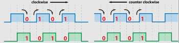
For this section, we intially considered using a button and a potentionmeter, but then discovered a rotary encoder, which encapsulated the functionality of both into a single component. We found a simple tutorial on the encoder, which explained how the two signals interact to tell the programming board which direction the board is turning, as well as providing some general tips on programming it.
Collin attempted to use ChatGPT to program the entirity of the encoder, but when I thought that it was not a proper display of knowledge and the incosistency of the program was very prevalent, I decided to try to program it myself using a combination of Collin’s old code and the website linked above. To start, I found the following pinout diagram on an Arduino Forum for the CNC shield and began to work from there.
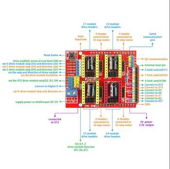
With this image, I knew that I wanted to connect the analog pins of the CNC shield to the encoder, as that would allow for the encoder’s direction to be read properly and still allow for basic digital communication. To wire this encoder, the GND and + pins are obviously for ground and power, respectively, the SW pin is for programming the button, the CLK pin is for output A and clockwise rotation, and the DT pin is for output B and the counter clockwise rotation. To measure the rotation of the encoder, we can check if they are equal when output A goes to 1, and the rotation is counterclockwise when so. Vice versa, the rotation is clockwise when output A and output B are not equal.
As I learned from the above tutorial, and alongsdie some help from ChatGPT, we knew that the method for making the encoder work would involve programming it to store a value determined by the amount of rotation of the encoder and stashing that value in a list each time the button is pressed. To decide the pins that would be used, we found on the website that the pins the encoder was connected to didn’t entirely matter, so we hooked them up to some available analog pins to be used a digital pins, which is a function built into the board. I chose pin A0 for the CLK, pin A3 for DT, and pin A1 for SW. Once again, there were several iterations of this code, so for the sake of conciseness, the final result of the testing will only be shown here.
There were two primary iterations for the encoder, with the first being the code itself that simply displays the output value, or “counter”, in the serial monitor, and the second having the potentionmeter integrated with the motors so that they can run subsequentially. The former code can be downloaded here, and the latter can be downloaded here.
Shown below is the latter program running, and this video shows the process of putting in the three inputs into the computer, and then the motors moving. The purpose of the first input is to determine the length of the wire for when it needs to be cut, the second is the length of the wire that will be exposed after stripping, and the final is the amount of times this length of wire will be cut.
This video displays the encoder working with the motors, and this code will be adapted so that after the inputs are made, the program will move the motors different amounts based on those values, and the program will display the information on a meaningful output that is not just the serial montior. To make this output, we programmed an OLED.
Integrating OLED with Rotary Encoder
In order to integrate the OLED, I incorporated some of the code and programming from Output Devices week. Using the Adafruit library and adapting code from the corresponding examples for the SSD1306 OLED, we got the OLED to work alongside the encoder.
The things that were entirely left the same were the stepper motor functions at the bottom, the current definitions for variables at the top, and the pinMode definitions in the setup function. The aspects that were changed are as follows:
The addition of the required libraries and # definitions, as well as the declaration of the OLED object.
#include <SPI.h>
#include <Wire.h>
#include <Adafruit_GFX.h>
#include <Adafruit_SSD1306.h>

#define SCREEN_WIDTH 128 // OLED display width, in pixels
#define SCREEN_HEIGHT 64 // OLED display height, in pixels

#define OLED_RESET     -1 // Reset pin # (or -1 if sharing Arduino reset pin)
#define SCREEN_ADDRESS 0x3D ///< See datasheet for Address; 0x3D for 128x64, 0x3C for 128x32
Adafruit_SSD1306 oled(SCREEN_WIDTH, SCREEN_HEIGHT, &Wire, OLED_RESET);
Putting the lines to initialize and start the OLED at the beginning of the setup function.
  Serial.begin(9600);

  // initialize OLED display with address 0x3C for 128x64
  if (!oled.begin(SSD1306_SWITCHCAPVCC, 0x3C)) {
    Serial.println(F("SSD1306 allocation failed"));
    while (true);
  }

  delay(2000);         // wait for initializing
  oled.clearDisplay(); // clear display

  oled.setTextSize(2);          // text size
  oled.setTextColor(WHITE);     // text color
  oled.setCursor(0, 0);        // position to display
  oled.println("Test."); // text to display
  oled.display();
  delay(1000);         // show on OLED
  oled.clearDisplay();
Integrating the OLED programming into the loop function and changing the displaying aspect of the encoder readings.
  oled.setTextSize(1);          // text size
  oled.setTextColor(WHITE);     // text color


  CLK_state = digitalRead(CLK_PIN);

  if (digitalRead(SW_PIN) == LOW) {

    Serial.println("Value Stored!");
    oled.display();
    storedValues[buttonPressCounter] = counter; // Store the current value
    buttonPressCounter++; // Increment button press counter
    if (buttonPressCounter >= 3) { // If pressed three times
      // Print all stored values
        oled.clearDisplay();
        oled.setCursor(5, 10);        // position to display
        oled.print("Length: ");
        oled.println(abs(storedValues[0]));
        length = abs(storedValues[0]);

        oled.setCursor(5, 20);
        oled.print("End Length: ");
        oled.println(abs(storedValues[1]));
        end_length = abs(storedValues[1]);

        oled.setCursor(5,30);
        oled.print("Amount: ");
        oled.println(abs(storedValues[2]));
        oled.display();
        valstored = true;
      }
      // Reset button press counter and clear stored values

    delay(250); // Debouncing delay
  }
After these changes were made and some other minor wiring troubleshooting, we were able to make the code fully work. There was still some math left to do in order to convert these values into actual working amounts for the program to run on, but this was good progress for now. The current status of the OLED was that it would display a test message at the start to confirm that the OLED is properly communicating over I2C, and then each time the button on the encoder is pressed, the screen will display which input the code is on.
Since all these devices and the motors were set up, we starting assembling the entire machine.
Cutting and Assembly
For the beginning part of the assembly, Collin showed me the OnShape plugin Kiri:Moto, which coudl convert each of the necessary pieces into DXFs to be laser cut on cardboard for a test cut. However, when I imported these DXFs into CorelDraw, I recieved an error saying “Unrecoverable Error,” but Collin told me to export them as a SVG instead of DXF, which worked. I was then able to laser cut the file to see roughly how the design would turn out.

From here, I simply cut out the same cuts on wood this time. Unfortunately, before I could remember to take photos of the entire cut alone, my partners assembled a some pieces using heat-set inserts to attach the 3D printed corner joints to the wood, thereby connecting the front, back, top, and inner channel holders together. Additionally, they placed the v-channels into the assembly using more heat-set inserts.
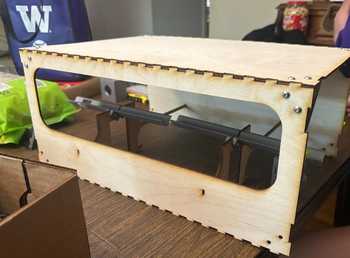
Now that we had the basic pieces, we began to assemble the gantry. The first step was to attach the bar for the gantry to the bottom wood piece, which was accomplished by Collin, so I do not entirely know how to explain how he obtained the bar and shortened to the proper length.

Then, Collin designed the mechanism for what would be on the gantry through screwing a 3D holder for one of the motors, as well as a piece for the wire cutters onto another 3D piece that holds the belt, all of which would be put onto the bearing plate.
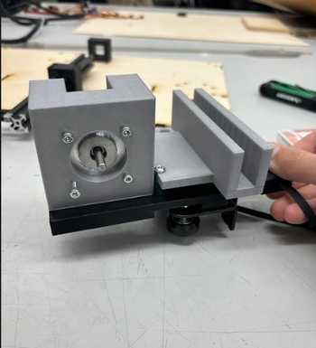

This part of the assembly was attached to the main body, the wire cutters were fit neatly into the slot, and an elastic string was looped around some different holes to serve as the pulley mechanism for the wire cutters.
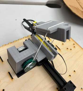
Alongside this gantry system and the previously displayed top section, we screwed in the remaining motors with their corresponding 3D cases, and assembled it all together! Fortunately, after a bit of finagling, we got everything in place and fitting nicely together.
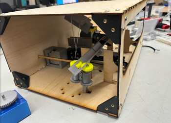
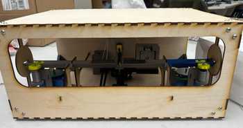
Since everything was in place, we got to the final steps.
Testing and Final Programming
The first step for this part of the process was to test each motor. After finding that the first motor wasn’t spinning properly, we looked at the TPU wheels and saw that they were grinding against the holes in the v-channel.
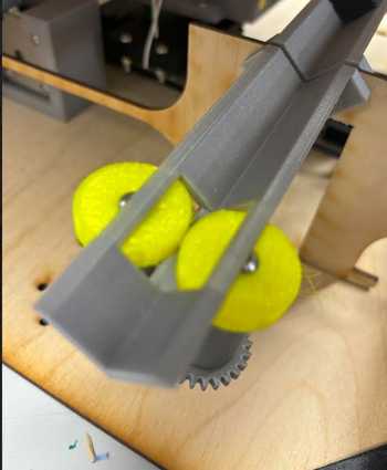
To fix this, Ryan widenned the gap on the 3D model and re-printed the file. While the belt worked fine, there were difficulties with the motor on the gantry meant to close the wire cutters. This, we believe, was due to the motor not having a flat edge on one side and instead being fully circular, as well as the string being under too much tension.
A second major issue that we encountered was how the wire, after being fed through those yellow TPU wheels, would sometimes get caught and force us to reset the program after pushing the wire back into place. The solution for this issue was the inclusion of 3D pieces that fit into the channel which would prevent the wire from coming up, so several of these were printed out.
A third issue that arose was various problems with the clamping motor and spool/gear. The first part of this was that the 3D print had one messy and one clean side, leading to it being caught on the messy 3D print many times, the second part was the aforementioned issue of the spool/gear coming off, and the final issue is that the motor simply would not rotate the gear fully and properly to clamp the wire cutters. We tried changing to stronger wire, but recieved no results.
The fourth and largest issue that we had to deal with was the realization that, after running the program many times and recieving the same result, the motor did not have enough power to strip the wire after it is clamped. This meant that all we could truly do was cut wires with the machine, which was very disappointing after all the effort.
The file for this section can be downloaded here, and a video showcasing the main process can be found on the group documentation
Reflection
The two weeks we worked on this were very trial and error intensive, which I believe could help in the process to get my final project to work. The many aspects of this helped those in our group cover each other’s weaknesses, as while I was not the best at 3D modeling, I have become fairly alright with programming, so I pulled my weight in that field. The parts about this that felt the best were the temporary moments where I thought the machine was going to work, but most of the time it always led to disappointment. This process seems far more simplified, excluding the 3D modeling, when looking back, so it could be interesting to design a simpler machine in the future. Future additions to this project could include getting the stripper to work and adding a soldering/tinning function to each side of the wire. Overall, this week was a very difficult one that sadly did not have a very satisfying ending.