Week 11: Input Devices
This week was focused on programming different input devices, such as sensors, and optionally trying to relate them to an output. I chose to work with the BNO-055 9-axis DOF sensor, which included an accelerometer, a gyroscope, and a magnetometer. This sensor was chosen due to how I planend to use it with my final project as my primary sensor. Much of what is accomplished in this week is based on previous weeks, so those should be read when necessary.
Requirements
Individual Assignment:
- Measure something: add a sensor to a microcontroller board that you have designed and read it.
Group Assignment:
- Probe an input device’s analog levels and digital signals.
Programming through Arduino UNO
As I generally try to do when programming different devices, I first programmed them on Arduino UNO. I found a guide by Adafruit, which detailed how to set up the connections and pins as well as some example code; however, I chose not to try and use the provided code. Instead, I downloaded the “Adafruit BNO055” library on Arduino IDE and loaded the example code named “read_all_data”. That file can be found here. The following is an image of the sensor that I chose to use.

To wire the sensor, I connected the GND pin to the GND pin of the Arduino UNO, the Vin pin to 5V, the SDA pin to A4, and the SCL pin to A5. I knew these values for the SDA and SCL already becasue of the I2C programming that I had already done in Outputs Week. I tried running the above code but recieved a very difficult error and an odd message in the serial monitor
avrdude: ser_open(): can't open device "\\.\COM5": A device attached to the system is not functioning
P� ���������0�<
����
�
Unsure of what either of these meant, I asked Richard Shan for help due to the knowledge he has of how things work on a deeper level with computers. Knowing that I tried switching wires and Arduino UNOs, he told me that my driver might be the issue. I went to here, downloaded the file, ran the “SETUP” executable, and then confirmed.
I restarted my computer, and while the first time I sent the code through, it successfully uploaded, there was no display in the serial monitor and subsequent attempts recieved similar errors. I tried restarting my computer, re-installing the driver, and other random solutions, to no avail. The few times that I managed to get it to go through to the serial monitor, I’d just recieve a message saying that the program failed. Eventually, I thought that it might be the jumper cabels that are causing the issue, so I soldered on header pins and used male to female jumper cables instead of the previous male to male. This time, after messing around with the code some more and re-uploading it a few times, I got it to display all the information!
This was a much longer process than I have represented here, but due to the inherent redundancy of that process, it will not be included lest I want this page to go ad infinitum.
Programming through ATtiny1614
Next, I wanted to program the board on a ATtiny1614, and since I already had done a similar process in Outputs Week, I chose to follow a similar workflow. I initally reused the board and pinouts that I already had milled and soldered, which worked quite well.
I was able to simply hook up the proper connections to from the SDA and SCL pins of the to the correct pins of the sensor and run the previous code.

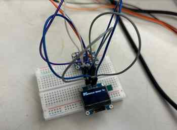
Now that the connection were correct this time, I ran the code once again after going into the Tools manager and selecting all the correct settings, such as the Programmer and the Chip. While it successfully went through, there was no way to know if the program actually worked, so I had to hook up an OLED screen to display the results. Once again, I used my preivous knowledge to use the “SSD1306Ascii” library to display the correct information with a library that takes up very little storage.
I modified the code to include the correct libraries and information, and I ended up with code that simply replaced every single serial print or println statement with an print statement based on the OLED object that is defined at the top of the code.
#include <Wire.h>
#include <Adafruit_Sensor.h>
#include <Adafruit_BNO055.h>
#include <utility/imumaths.h>
#include "SSD1306Ascii.h"
#include "SSD1306AsciiWire.h"

// 0X3C+SA0 - 0x3C or 0x3D
#define I2C_ADDRESS 0x3C

// Define proper RST_PIN if required.
#define RST_PIN -1

SSD1306AsciiWire oled;


/* Set the delay between fresh samples */
uint16_t BNO055_SAMPLERATE_DELAY_MS = 1000;

// Check I2C device address and correct line below (by default address is 0x29 or 0x28)
//                                   id, address
Adafruit_BNO055 bno = Adafruit_BNO055(55, 0x28, &Wire);

void setup()
{
  Wire.begin();
  Wire.setClock(400000L);

  #if RST_PIN >= 0
  oled.begin(&Adafruit128x64, I2C_ADDRESS, RST_PIN);
#else // RST_PIN >= 0
  oled.begin(&Adafruit128x64, I2C_ADDRESS);
#endif // RST_PIN >= 0

  oled.setFont(Adafruit5x7);
  Serial.begin(9600);
  oled.println("test");
  while (!Serial) delay(10);  // wait for serial port to open!

  oled.println("Orientation Sensor Test"); oled.println("");
  oled.print("test 2");
  /* Initialise the sensor */
  if (!bno.begin())
  {
    /* There was a problem detecting the BNO055 ... check your connections */
    Serial.println("No BNO055 detected; Check your wiring or I2C ADDR.");
    while (1);
  }

  delay(1000);
}

void loop()
{
  //could add VECTOR_ACCELEROMETER, VECTOR_MAGNETOMETER,VECTOR_GRAVITY...
  oled.clear();
  delay(100);
  sensors_event_t orientationData , angVelocityData , linearAccelData, magnetometerData, accelerometerData, gravityData;
  bno.getEvent(&orientationData, Adafruit_BNO055::VECTOR_EULER);
  bno.getEvent(&angVelocityData, Adafruit_BNO055::VECTOR_GYROSCOPE);
  bno.getEvent(&linearAccelData, Adafruit_BNO055::VECTOR_LINEARACCEL);
  bno.getEvent(&magnetometerData, Adafruit_BNO055::VECTOR_MAGNETOMETER);
  bno.getEvent(&accelerometerData, Adafruit_BNO055::VECTOR_ACCELEROMETER);
  bno.getEvent(&gravityData, Adafruit_BNO055::VECTOR_GRAVITY);

  printEvent(&orientationData);
  printEvent(&angVelocityData);
  printEvent(&linearAccelData);
  printEvent(&magnetometerData);
  printEvent(&accelerometerData);
  printEvent(&gravityData);

  // int8_t boardTemp = bno.getTemp();
  // Serial.println();
  // Serial.print(F("temperature: "));
  // Serial.println(boardTemp);

  uint8_t system, gyro, accel, mag = 0;
  bno.getCalibration(&system, &gyro, &accel, &mag);
  oled.println();
  oled.print("Calibration: Sys=");
  oled.println(system);
  oled.print(" Gyro=");
  oled.println(gyro);
  oled.print(" Accel=");
  oled.println(accel);
  oled.print(" Mag=");
  oled.println(mag);

  oled.println("--");
  delay(BNO055_SAMPLERATE_DELAY_MS);
}

void printEvent(sensors_event_t* event) {
  double x = -1000000, y = -1000000 , z = -1000000; //dumb values, easy to spot problem
  if (event->type == SENSOR_TYPE_ACCELEROMETER) {
    oled.print("Accl:");
    x = event->acceleration.x;
    y = event->acceleration.y;
    z = event->acceleration.z;
  }
  else if (event->type == SENSOR_TYPE_ORIENTATION) {
    oled.print("Orient:");
    x = event->orientation.x;
    y = event->orientation.y;
    z = event->orientation.z;
  }
  else if (event->type == SENSOR_TYPE_MAGNETIC_FIELD) {
    oled.print("Mag:");
    x = event->magnetic.x;
    y = event->magnetic.y;
    z = event->magnetic.z;
  }
  else if (event->type == SENSOR_TYPE_GYROSCOPE) {
    oled.print("Gyro:");
    x = event->gyro.x;
    y = event->gyro.y;
    z = event->gyro.z;
  }
  else if (event->type == SENSOR_TYPE_ROTATION_VECTOR) {
    oled.print("Rot:");
    x = event->gyro.x;
    y = event->gyro.y;
    z = event->gyro.z;
  }
  else if (event->type == SENSOR_TYPE_LINEAR_ACCELERATION) {
    oled.print("Linear:");
    x = event->acceleration.x;
    y = event->acceleration.y;
    z = event->acceleration.z;
  }
  else if (event->type == SENSOR_TYPE_GRAVITY) {
    oled.print("Gravity:");
    x = event->acceleration.x;
    y = event->acceleration.y;
    z = event->acceleration.z;
  }
  else {
    oled.print("Unk:");
  }

  oled.print("\tx= ");
  oled.print(x);
  oled.print(" |\ty= ");
  oled.print(y);
  oled.print(" |\tz= ");
  oled.println(z);
}
The wiring to hook this up on a breadboard was very clogged and messy, yet a test program fortunately got sent to the OLED on the first try!
However, the program for the sensor was not yet going through, so I had to mess around with the uploaded before it eventually worked.
Now that I knew it could work, I had to mill out a board to fulfill the requirements for this week. I made a simple schematic and corresponding PCB design in KiCad pretty quickly. In this file, I used the KiCad fab library to add symbols and footprints to the design and link them together.

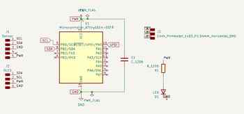
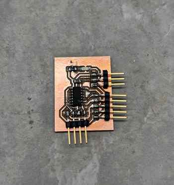
I exported the Gerber files using the plot function and imported them into Bantam Milling Software. Following our lab’s workflow, detailed in previous documentation, I milled out these Gerber files and soldered on correct components. I included an indicator LED to make sure that power was successfully being supplied to the board.
| Components |
|---|
| ATtiny1614 |
| 1uF Capacitor |
| Blue LED |
| 490 Ohm Resistor |
| 1x03 Conn. Header Pins |
| 1x04 Conn. Header Pins |
| 1x05 Conn. Header Pins |
Once I had the board milled out and all the components were gathered, I soldered on the pieces to the board. The only difficulties were that there were a couple traces that needed to be cut due to them bridging and the solder paste that I used spread around oddly after being heated.
With the board now done, I just had to do the same connections as I did on the breadboard. This process was simplified due to how I had set up the KiCad file to already have the necessary connections all ordered for each piece of the board, meaning that I didn’t have to cross any wires to get the different parts of it to work.

The last thing to do was to just run the program and get it to work, which happened without errors!
This was the final step in the process, and I was glad to have finally completed it, since it meant that the difficulties from Machine Week were starting to settle down.
Group Project
The goal of the group project was to measure my sensor and read the signals, digital as well as analog, to understand how the I2C communication worked. The page for our site can be found here.
Individual Contribution
For this week, I was partnered with Alana Duffy. Since we were doing my sensor and she was not done with hers, I ended up doing the majority of the work and all of the documenting, though that is to be expected since it was my input.
Reflection
This week was a very calm one that was carried significantly by the previous work I had done in Outputs Week and the recent review of how to use an OLED done in Machine Week. Coming off of Machine Week made this week a little difficult for time, and the fact that my sensor did not arrive the first time it was meant to also added to the difficulties of this process. However, I was still able to accomplish everything, and this was an overall nice week that helps me greatly with my Final Project.