My Final Project
This is where I will start defining my final project idea and start to get use to the documentation process.
Questions that need to be answered :
- What does it do?
- Who’s done what beforehand?
- What did you design?
- What materials and components were used?
- Where did they come from?
- How much did they cost?
- What parts and systems were made?
- What processes were used?
- What questions were answered?
- What worked? What didn’t?
- How was it evaluated?
- What are the implications?
Week 01 - Plan and sketch for a potential final project
Socialization acceptance device
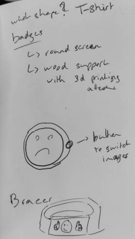
This idea came to me thinking about people with autistic syndrom for whom socialization is a big difficulty just like the ability to express their mindset. A lot of them have the will to meet and bond with people but they don’t always have the social skill to do so. At first, I thought on made it appear as a message on a t-shirt to be seen by everyone. A less difficult choice would be on a wearable small screen maybe on a bracer or as badges.
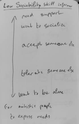
I imagined a fidget as an input device. Fidgets are often used with persons with autism for regulating themselves, through manipulating, massaging or chewing.

The person could use to express its mindset, through a mood gauge and socialbility acceptance. With a potentiometer, they could share their mood from angry, sad, neutral, good, or happy. With a bunch of switches, they could share their level of acceptance of socialization from “I need to be alone” to “I need support”. Designing it made me re-think with a dual-scale “mood/interaction acceptance”

Week 02 - Computer Aided Design
Input device
During the Computer aided design week, I designed a 3D remote device for my final project.
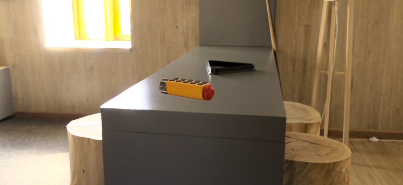
The user couldn’t enter its mood through through the potentiometer and enter his interaction acceptance through the switch activated. To validate the state and send the response to an output device, he needs to push the red button.
Output display
For the output, I thought to display a smiley face as it’s an international form of communicating even without reading hability.
I started making a table, combining a mood scale and intercation acceptance scale with smileys. Combining them with Emoji Kitchen could provide a reperesentation of the user’s mindset.
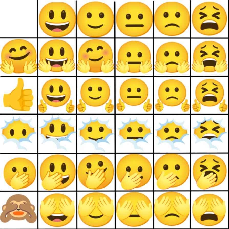
I also started to make a svg file of smileys to make them appear on the input device with cutting or engraving.

Week 03 - Computer controlled cutting
I decided to make a plywood model of my final project to see the size. I’m aware that living hinge aren’t strong enough for something that will be manipulated a lot. I have rebuilt my model on fusion using metal sheet.

On my third attempt, I could finally make a nice lasercut and assemble it.
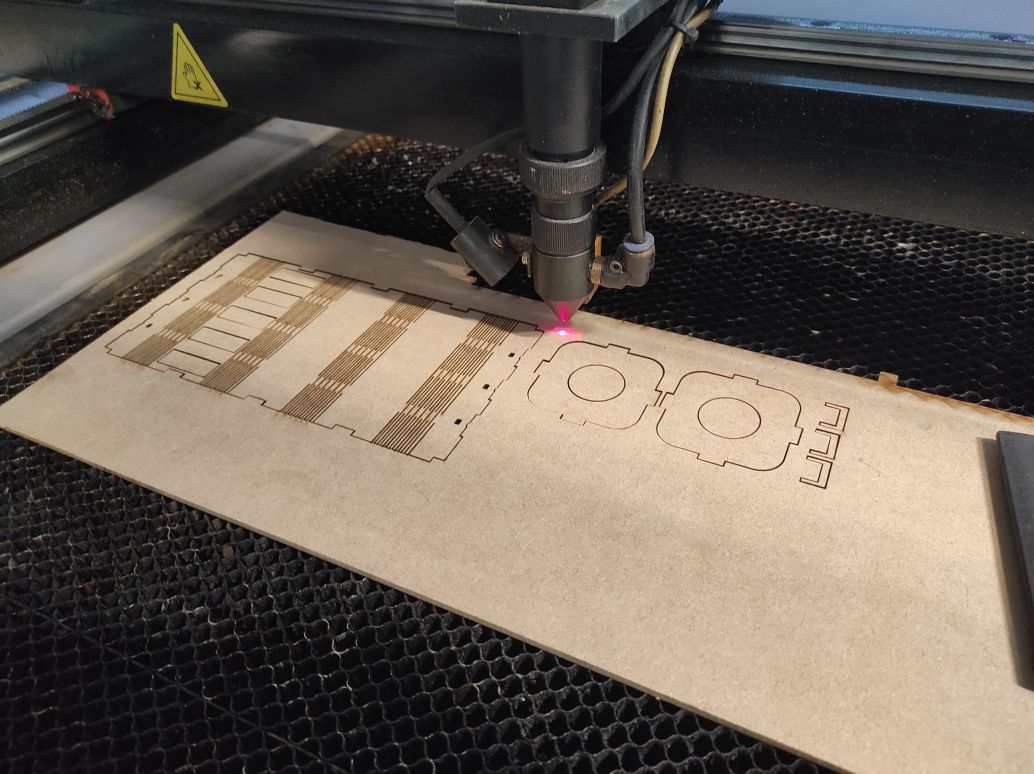
The hinges don’t completely fit, probably because the pattern make it too loose. The size could be a bit longer to facilitate manipulation between the two hands and i’d like it to be thinner to handed it more easily.

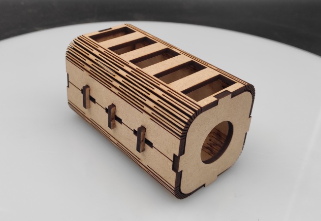
For my final project, I don’t think I will use the model I created this week, beacuse it’s too fragile and absolutely not ergonomic. Anyway, it helps me defining more precisely what I need : a shape more elongated to facilitate manibpulation, a more flexible material like rubber or silicone, a reccessed button to avoid unattended push.
Week 06 - Embedded programming
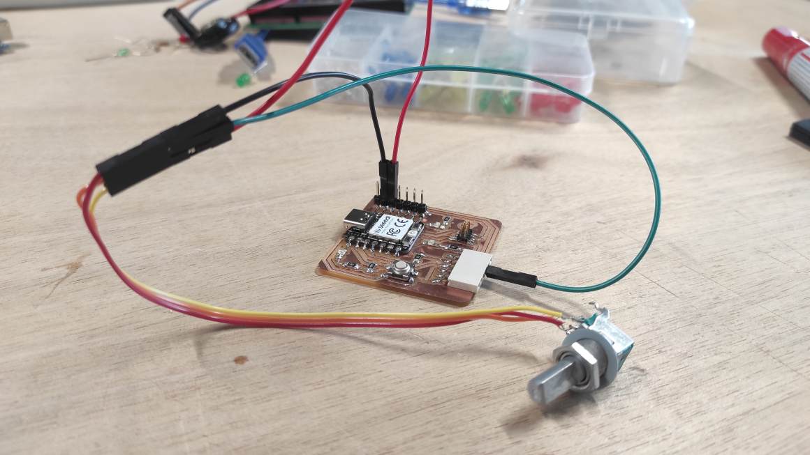
During this week, I learned about programming on the RP2040 Micro-controller and chose to test potentiometer programming in prevision of my final project.
To connect the potentiometer to my board, I added connexion header on it to have a better access at the 3.3V pin.
A2 and A3 are available but A3 is link to a 1000 ohms resistor. Potentiometer being a variable resistor, I thought using the pin without resistor was more pertinent. But after testing the two of them, they both works well.
I made this setup.
ChatGPT provided me this code to this prompt and some specification to correct issues:
make an arduino code for a potentiometer lighting 1 then 2 then 3 led as it is turn.
const int potPin = A2;  // analog pin for the potentiometer
const int ledPin1 = 26;  // the number of the first LED pin
const int ledPin2 = 0;  // the number of the second LED pin
const int ledPin3 = 1;  // the number of the third LED pin
const int numLEDs = 3;  // number of LEDs

void setup() {
  pinMode(ledPin1, OUTPUT);
  pinMode(ledPin2, OUTPUT);
  pinMode(ledPin3, OUTPUT);
}

void loop() {
  // Read the potentiometer value
  int potValue = analogRead(potPin);

  // Map the potentiometer value to the range of LEDs
  int ledLevel = map(potValue, 0, 1023, 0, numLEDs + 1);

  // Turn on the LEDs based on the mapped value
  digitalWrite(ledPin1, ledLevel >= 1);
  digitalWrite(ledPin2, ledLevel >= 2);
  digitalWrite(ledPin3, ledLevel >= 3);

  delay(100);  // Adjust delay as needed to control the responsiveness
}
potPin constant define the Analog pin on A2 and don’t need to be set as input in the setup part.In the main program,
analogRead will get a value between 0 and 1023 from the potentiometer and make a variable from it.
Then it creates from it a ledLevel variable with the map functions. This functions will make corresponding potValue (between 0 and 1023) and ledLevel (between 0 and 4 “pinLEd+1”)
Then it will turn on LED for each ledLevel, corresponding to the potentionmeter value.
The final code is here
Serial Analog test
I also test AnalogInOutSerial example to have a monitor feedback of the value of the potentiometer.

I change the code a bit to turn on all LEDs with the fade.
The final code is here
OLED Screen
For testing an OLED screen, I used the SSD1306 screen with the U8g2 library as recommended in Neil’s documentation.

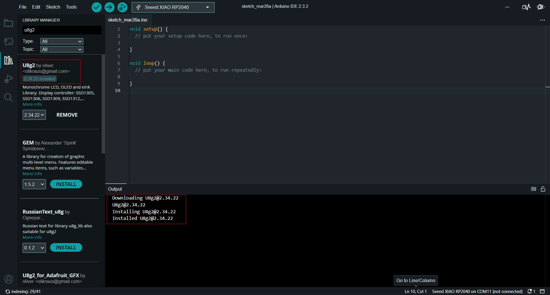
I used chat GPT to generate a code to display a text. I modified it a little to set the pins SDA and SCL and change the default text.
Here’s the final code :
#include <U8g2lib.h>
#include <Wire.h>

// OLED display constructor
U8G2_SSD1306_128X64_NONAME_F_HW_I2C u8g2(U8G2_R0, /* reset=*/ U8X8_PIN_NONE, /* clock=*/ 7, /* data=*/ 6);

void setup(void) {
  // Initialize the OLED display
  u8g2.begin();
}

void loop(void) {
  // Clear the screen
  u8g2.clearBuffer();

  // Set font and position
  u8g2.setFont(u8g2_font_ncenB14_tr);
  u8g2.setCursor(0, 20); // Set position (x, y)

  // Write text to the screen
  u8g2.print("It works! _o/");

  // Send the buffer to the display
  u8g2.sendBuffer();

  // Delay to control the refresh rate
  delay(1000);
}

Unfortunately, my I2C connector broke but I learned from datasheet that all of the pins have a functions for I2C. I noticed that not all kind of characters are displayed. I could explore that later. I also should explore image displaying.
Week 11 - Input device
Personnal assignment - I have to test a selector and switches and program different response mixing them. If possible try with screen display then with e-paper
During this week, I made a bunch of tests to understand how the selector works. I also implement what I learned from output device week and a bit more about OLED screen.
I ended up with this code :
#define pinCLK 1       // CLK pin connected to GPIO 1
#define pinDT  2       // DT pin connected to GPIO 2
#define pinSW  3       // SW pin connected to GPIO 3

#include <U8g2lib.h>
#include <Wire.h>

// OLED display constructor
U8G2_SSD1306_128X64_NONAME_F_HW_I2C u8g2(U8G2_R0, /* reset=*/ U8X8_PIN_NONE, /* clock=*/ 7, /* data=*/ 6);

int count = 0;    // Var to know how many clicks occured (increment clockwise and decrement counter_clockwise)
int previousStateSW;           // Var to memorize previous SW state to compare it with actual state
int previousStateCLK;          // Var to memorize previous CL state to compare it with actual state

void setup() {

    Serial.begin(9600);

    // Initialize the OLED display
    u8g2.begin();

    pinMode(pinSW, INPUT_PULLUP);         // INPUT_PULLUP to avoid 'floating'
    pinMode(pinDT, INPUT);
    pinMode(pinCLK, INPUT);

    previousStateSW  = digitalRead(pinSW);    // initial value for SW
    previousStateCLK = digitalRead(pinCLK);   // initial value for CLK

    delay(200); // delay to stabilize signal before the loop
}

void loop() {

    int actualStateCLK = digitalRead(pinCLK); // reading CLK value
    int actualStateDT  = digitalRead(pinDT);  // reading DT value
    int actualStateSW  = digitalRead(pinSW);  // reading SW value

    // Clear the screen
    u8g2.clearBuffer();

    // *************************
    // Push Button verification
    // *************************

    if (actualStateSW != previousStateSW) {    // Checking if SW state has changed
        previousStateSW = actualStateSW;      // Save new state

        if (actualStateSW == LOW) {
            Serial.println(F("SW Button pushed"));     // Display State on serial monitor

            // Set font and position
            u8g2.setFont(u8g2_font_ncenB14_tr);
            u8g2.setCursor(0, 20); // Set position (x, y)
            // Write text to the screen
            u8g2.print("SW Button :");

            u8g2.setCursor(0, 40); // Set position (x, y)
            // Write text to the screen
            u8g2.print("Pushed");

        } else {
            Serial.println(F("SW Button released"));

            u8g2.setFont(u8g2_font_ncenB14_tr);
            u8g2.setCursor(0, 20); // Set position (x, y)
            // Write text to the screen
            u8g2.print("SW Button :");

            u8g2.setCursor(0, 40); // Set position (x, y)
            // Write text to the screen
            u8g2.print("Released");
        }
        // Send the buffer to the display
        u8g2.sendBuffer();

        delay(10); // Delay to avoid rebounce
    }

    // ***************************
    // Rotary encoder verification
    // ***************************

    if (actualStateCLK != previousStateCLK) {       // Checking if SW state has changed
        previousStateCLK = actualStateCLK;           // Save new state

        if (actualStateCLK == LOW) {

            if (actualStateCLK != actualStateDT) {   // comparing CLK and DT, if they're different, direction is counter-clockwise
                count--;                            // decrement counter
                Serial.print(F("Direction = counter-clockwise | Counter value = "));   // Display value on Serial Monitor
                Serial.println(count);

                u8g2.setFont(u8g2_font_ncenB10_tr);
                u8g2.setCursor(0, 15); // Set position (x, y)

                // Write text to the screen
                u8g2.print("Direction :");

                u8g2.setFont(u8g2_font_ncenB08_tr);
                u8g2.setCursor(0, 28); // Set position (x, y)
                u8g2.print("counter-clockwise");

                u8g2.setFont(u8g2_font_ncenB10_tr);
                u8g2.setCursor(0, 45); // Set position (x, y)
                // Write text to the screen
                u8g2.print("Counter value = ");

                u8g2.setCursor(0, 60); // Set position (x, y)
                u8g2.println(count);

                // Send the buffer to the display
                u8g2.sendBuffer();
            }
            else {                                   // when CLK and DT are similar, direction is clockwise
                count++;                             // increment counter
                Serial.print(F("Direction = clockwise | Counter value = "));   // Display value on Serial Monitor
                Serial.println(count);

                 u8g2.setFont(u8g2_font_ncenB10_tr);
                u8g2.setCursor(0, 15); // Set position (x, y)

                // Write text to the screen
                u8g2.print("Direction :");


                u8g2.setCursor(0, 30); // Set position (x, y)
                u8g2.print("clockwise");

                u8g2.setCursor(0, 45); // Set position (x, y)
                // Write text to the screen
                u8g2.print("Counter value = ");

                u8g2.setCursor(0, 60); // Set position (x, y)
                u8g2.println(count);

                // Send the buffer to the display
                u8g2.sendBuffer();
            }

            delay(1);   // delay to avoid CLK rebounce
        }
    }
}
The results was very satisfactory.
I still need to implement in the code the limit to the counter value to the number I decided (I think of -2 to 2 for the 5 levels of mood) and display an image instead of strings.
I didn’t have time to work on e-paper but I found some WEMOS ePaper 2.13 Shield with driver.
Week 13 - Networking and communication
During this week, I succeeded to display on a distant screen, inputs from remote controller board.
Using the previous rotary encoder code, I modified it with with blocks of code from examples of ESP NOW.
I succeeded to have a feedback of the SW button being pushed or released but not from the rotary encoder.
- Code for periperal display of message from controller
- Code for controller transmitting rotary encoder inputs
The cheap yellow screen library also need modification to work.
Week 14 - Interface and application programming
I made an html interface that could be control with an input device through serialport.
<!DOCTYPE html>
<html lang="en">
<head>
    <meta charset="UTF-8">
    <meta name="viewport" content="width=device-width, initial-scale=1.0">
    <title>IMU Data and Mindset Selector</title>
    <style>
        .container {
            display: flex;
            justify-content: space-around;
            margin-bottom: 20px;
            max-height: 20%;
        }
        .image-container {
            text-align: center;
        }
        .image-container img {
            max-width: 100%;
            max-height: 100px;
        }
        .btn-container {
            text-align: center;
            margin-bottom: 20px;
        }
        .btn {
            padding: 10px 20px;
            background-color: #007bff;
            color: #fff;
            border: none;
            cursor: pointer;
            margin: 0 10px; /* Add some spacing between buttons */
        }
        #result-container {
            text-align: center;
            margin-top: 20px;
        }
        #result-button-container {
            text-align: center;
            margin-bottom: 20px;
        }
        #result-image {
            max-width: 20%; /* Adjust the maximum width of the result image container */
            margin: 0 auto; /* Center the result image horizontally */
        }
        #result-image img {
            max-width: 100%; /* Ensure the result image fits within its container */
            height: auto; /* Maintain aspect ratio */
        }
    </style>
</head>
<body>

<div class="container">
    <div class="image-container">
        <h2>Mood</h2>
        <div id="image-container1">
            <img src="03_smiley.jpg" alt="Image" data-value="3">
        </div>
        <div class="btn-container">
            <button class="btn" onclick="previousImage(1)">Previous</button>
            <button class="btn" onclick="nextImage(1)">Next</button>
        </div>
    </div>
    <div class="image-container">
        <h2>Interaction acceptance</h2>
        <div id="image-container2">
            <img src="30_smiley.jpg" alt="Image" data-value="30">
        </div>
        <div class="btn-container">
            <button class="btn" onclick="previousImage(2)">Previous</button>
            <button class="btn" onclick="nextImage(2)">Next</button>
        </div>
    </div>
</div>

<div id="result-button-container">
    <button class="btn" onclick="addValues()">Set</button>
</div>

<div id="result-container">
    <h2>Mindset</h2>
    <div id="result-text"></div>
    <div id="result-image"></div>
</div>

<!-- Button to trigger the open_IMU function -->
<button class="btn" value="Open IMU" onclick="open_IMU()">Open IMU</button>

<!-- Container to display the container index value -->
<div id="container-index-value"></div>

<!-- JavaScript code -->
<script>
    var currentIndex1 = 2; // Index for the first image array
    var currentIndex2 = 2; // Index for the second image array
    var images1 = ["05_smiley.jpg", "04_smiley.jpg", "03_smiley.jpg","02_smiley.jpg", "01_smiley.jpg"];
    var images2 = ["50_smiley.jpg", "40_smiley.jpg", "30_smiley.jpg", "20_smiley.jpg", "10_smiley.jpg"];
    var values1 = [5, 4, 3, 2, 1];
    var values2 = [50, 40, 30, 20, 10];
    var allImages = [
        { src: "smiley_mix11.jpg", value: 11 },
        { src: "smiley_mix12.jpg", value: 12 },
        { src: "smiley_mix13.jpg", value: 13 },
        { src: "smiley_mix14.jpg", value: 14 },
        { src: "smiley_mix15.jpg", value: 15 },
        { src: "smiley_mix21.jpg", value: 21 },
        { src: "smiley_mix22.jpg", value: 22 },
        { src: "smiley_mix23.jpg", value: 23 },
        { src: "smiley_mix24.jpg", value: 24 },
        { src: "smiley_mix25.jpg", value: 25 },
        { src: "smiley_mix31.jpg", value: 31 },
        { src: "smiley_mix32.jpg", value: 32 },
        { src: "smiley_mix33.jpg", value: 33 },
        { src: "smiley_mix34.jpg", value: 34 },
        { src: "smiley_mix35.jpg", value: 35 },
        { src: "smiley_mix41.jpg", value: 41 },
        { src: "smiley_mix42.jpg", value: 42 },
        { src: "smiley_mix43.jpg", value: 43 },
        { src: "smiley_mix44.jpg", value: 44 },
        { src: "smiley_mix45.jpg", value: 45 },
        { src: "smiley_mix51.jpg", value: 51 },
        { src: "smiley_mix52.jpg", value: 52 },
        { src: "smiley_mix53.jpg", value: 53 },
        { src: "smiley_mix54.jpg", value: 54 },
        { src: "smiley_mix55.jpg", value: 55 },
    ];

    async function open_IMU() {
        try {
            // Requesting the serial port
            const port = await navigator.serial.requestPort();

            // Opening the serial port
            await port.open({ baudRate: 115200, bufferSize: 1 });

            // Getting the reader for the port
            const reader = port.readable.getReader();

            while (true) {
                // Waiting for line end
                let lineEnd = false;
                let line = '';
                while (!lineEnd) {
                    const { value, done } = await reader.read();
                    let chr = String.fromCharCode(value[0]);
                    line += chr;
                    if (chr === '\n' || done) lineEnd = true;
                }

            if (line.trim() === "SW Button pushed") {
                // If the button is pushed, call addValues
                addValues();
            } else if (line.trim() === "clockwise") {
                // If the rotation is clockwise, call nextImage
                nextImage(1);
            } else if (line.trim() === "counter-clockwise") {
                // If the rotation is counter-clockwise, call previousImage
                previousImage(1);
            }

                // Extracting container index
                const vars = line.split(',');
                const containerIndex = vars[0].trim().toString(); // Convert to string

                // Updating the container index value on the webpage
                document.getElementById("container-index-value").innerText = "Container Index: " + containerIndex;
            }
        } catch (error) {
            // Handling any errors that occur during the process
            console.error("An error occurred:", error);
        }
    }

    function previousImage(containerIndex) {
        if (containerIndex === 1) {
            if (currentIndex1 === 0) {
                return; // Do nothing if already at the first image
            }
            currentIndex1--;
            updateImage(1);
        } else if (containerIndex === 2) {
            if (currentIndex2 === 0) {
                return; // Do nothing if already at the first image
            }
            currentIndex2--;
            updateImage(2);
        }
    }

    function nextImage(containerIndex) {
        if (containerIndex === 1) {
            if (currentIndex1 === images1.length - 1) {
                return; // Do nothing if already at the last image
            }
            currentIndex1++;
            updateImage(1);
        } else if (containerIndex === 2) {
            if (currentIndex2 === images2.length - 1) {
                return; // Do nothing if already at the last image
            }
            currentIndex2++;
            updateImage(2);
        }
    }

    function updateImage(containerIndex) {
        var displayedImage;
        if (containerIndex === 1) {
            displayedImage = document.getElementById("image-container1").getElementsByTagName("img")[0];
            displayedImage.src = images1[currentIndex1];
            displayedImage.dataset.value = values1[currentIndex1];
        } else if (containerIndex === 2) {
            displayedImage = document.getElementById("image-container2").getElementsByTagName("img")[0];
            displayedImage.src = images2[currentIndex2];
            displayedImage.dataset.value = values2[currentIndex2];
        }
    }

    function addValues() {
        var value1 = values1[currentIndex1];
        var value2 = values2[currentIndex2];
        var result = value1 + value2;

        // Find the image object with the matching value
        var resultImage = allImages.find(function(image) {
            return image.value === result;
        });

        if (resultImage) {
            var resultImageSrc = resultImage.src;
            var resultImageValue = resultImage.value; // Get the personalized value
    //        document.getElementById("result-text").innerText = "Result: " + result + " (" + resultImageValue + ")"; //
            document.getElementById("result-image").innerHTML = "<img src='" + resultImageSrc + "' alt='Result Image'>";
        } else {
            document.getElementById("result-text").innerText = "Result: Invalid";
            document.getElementById("result-image").innerHTML = ""; // Clear previous result image
        }
    }
</script>
</body>
</html>
#define pinCLK 1       // CLK pin connected to GPIO 1
#define pinDT  2       // DT pin connected to GPIO 2
#define pinSW  3       // SW pin connected to GPIO 3

int count = 0;    // Var to know how many clicks occured (increment clockwise and decrement counter_clockwise)
int previousStateSW;           // Var to memorize previous SW state to compare it with actual state
int previousStateCLK;          // Var to memorize previous CL state to compare it with actual state

void setup() {

    Serial.begin(9600);

    pinMode(pinSW, INPUT_PULLUP);         // INPUT_PULLUP to avoid 'floating'
    pinMode(pinDT, INPUT);
    pinMode(pinCLK, INPUT);

    previousStateSW  = digitalRead(pinSW);    // initial value for SW
    previousStateCLK = digitalRead(pinCLK);   // initial value for CLK

    delay(200); // delay to stabilize signal before the loop
}

void loop() {

    int actualStateCLK = digitalRead(pinCLK); // reading CLK value
    int actualStateDT  = digitalRead(pinDT);  // reading DT value
    int actualStateSW  = digitalRead(pinSW);  // reading SW value

// *************************
// Push Button verification
// *************************

    if(actualStateSW != previousStateSW) {    // Checking if SW state has changed
        previousStateSW = actualStateSW;      // Save new state

        if(actualStateSW == LOW)
            Serial.println(F("SW Button pushed"));     // Display State on serial monitor
        else
            Serial.println(F("SW Button released"));

        delay(10); // Delay to avoid rebounce
    }

// ***************************
// Rotary encoder verification
// ***************************

    if (actualStateCLK != previousStateCLK) {
        delayMicroseconds(200); // Debounce delay
        if (digitalRead(pinCLK) == actualStateCLK) { // Check if the CLK signal has settled
            previousStateCLK = actualStateCLK;

    if(actualStateCLK == LOW) {

        if(actualStateCLK != actualStateDT) {   // comparing CLK and DT, if they're different, direction is counter-clockwise
            count++;                            // decrement counter
            Serial.println(F("clockwise"));   // Display value on Serial Monitor
//            Serial.println(count);
        }
    else {                                   // when CLK and DT are similar, direction is clockwise
        count--;                             // increment counter
        Serial.println(F("counter-clockwise"));   // Display value on Serial Monitor
//        Serial.println(count);
}

    }
    }

}
}
I create an online version of the interface to test it.
I also wanted to try it on phone but Android Chrome does not allowed serial port communication
Next weeks Schedule :
Week 12 - Molding and casting Create Molding from 3D scan of handshaped model of the fidget for more organic shape. Have to define how every input assembly with it.
Week 13 - Networking and casting
Work on communication between Fidget and Display. Actually working cable, find more easy way to communicate. Wired, distant, inductive, nfc ?
Week 14 - Interface and application programming Send images on micro-controller memory - choose images from switch and selector - display images on screen
Week 15 - Wildcard week Create support for display screen
Week 16 - Apllications and implicatiosn Create support for display screen
Week 17 - Systeme integration Debugging
Week 18 -