Final Project - Oracle
I am not religious, and I don’t really believe in higher power, but I believe in placebo effect. Sometimes when I’m down, I would like to receive a divine advice, some sort of encouragement to find inner strength, even though it’s made up.

|

|
Therefore, in this project, I will make an Oracle -> a device that will give you your personalized advice, maybe based on the religious texts. You can imagine it as Chinese fortune cookies, but more personal.
Mood board
I like the “biblically accurate angels” posts. There are many different types of angels mentioned in the bible.
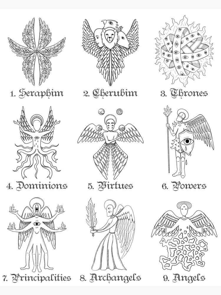
I think the cutest of them all are the seraphim’s and thrones! They have many eyes to see everything (and are allegedly most powerful), so those are great angels to receive the Oracle from.
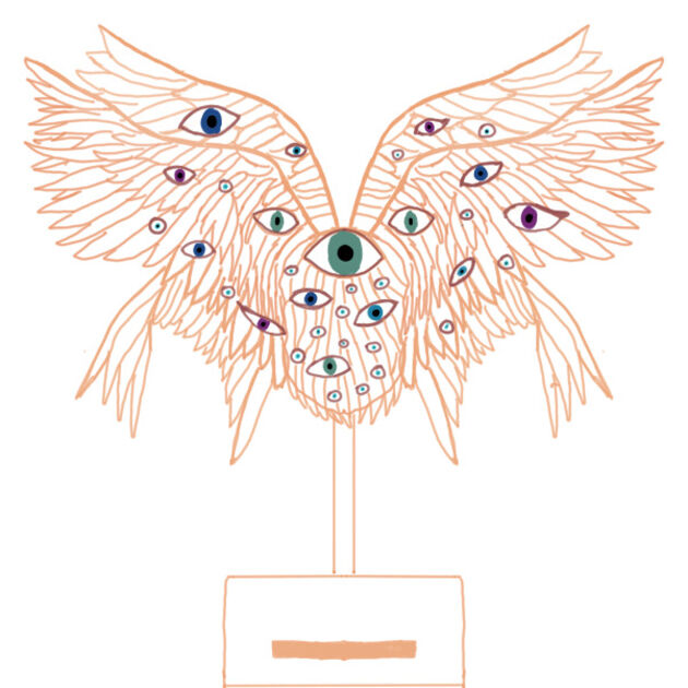
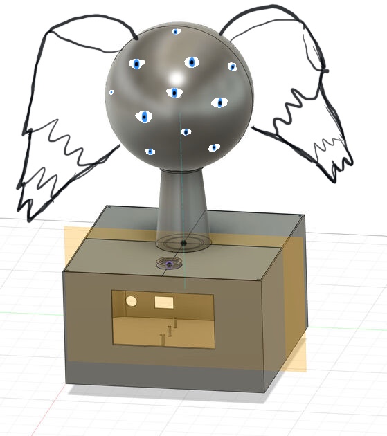
I then browsed the internet for some inspiration, and made a mood board.

(Sources of the images (from top right corner) here, here, here, here and here)
Based on that, I made my sketch:
How will it work from user perspective (simplified)
- register online, and fill up a form with your basic information
- add your fingerprint to the database
- once a day, you will be able to receive a “prophecy” from a great oracle
- you come to the oracle, scan the finger and get a small paper with divine advice
How will it work behind the scenes
Diagram:

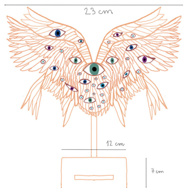
Sizes:
Components:
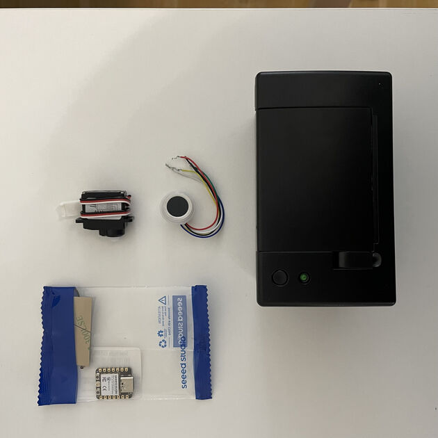
- Thermal printer - Adafruit Mini Thermal Receipt printer
- Fingerprint scanner - Capacitive Fingerprint Sensor
- Servo motor - SM-S2309S
- Microcontroller - Xiao ESP32C3
Project plan
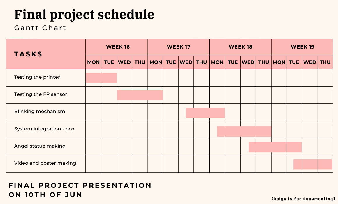
Testing the thermal printer
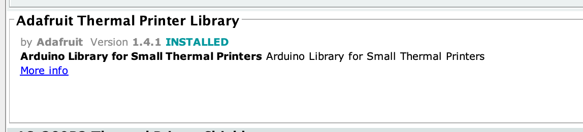
I started to test the thermal printer. It is the Adafruit Mini Thermal Receipt printer.
The documentation page about this printer says that when you connect it to power, and long press the button, it will by default print a test page.
So I used the power supply, and set it up according to the printers datasheet (5-9V and more than 1.5A). However, when I long pressed, the printer moved the paper, but haven’t printed anything. Suspicious!
I tried both sides of the paper, different sizes but nothing worked. So I moved on and tried to use the recommended library, and some example code from it.
Nothing was printing! I even used my arch nemesis oscilloscope to see if the UART works as intended, to see if we are really sending the data from the XIAO to the printer.
Finally, I remembered that in the UART, the receiver pin (RX) and transmitter pin (TX) should be connected not to each other (like ground to ground) but rather the TX from the microcontroller to RX from the printer and the RX from microcontroller to TX of the printer. I remember making this mistake in the past, hope I will learn now.
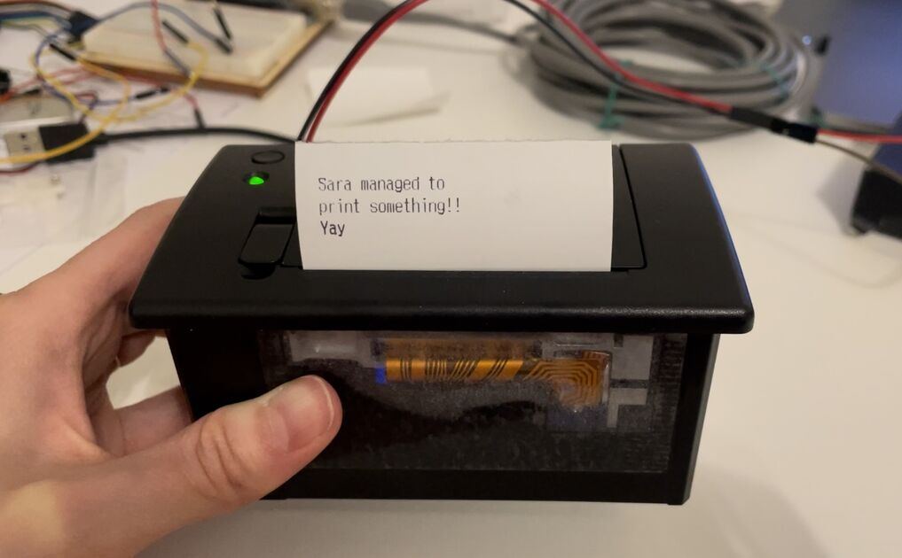
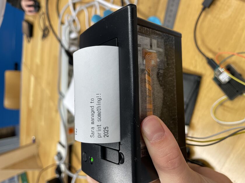
At last, the printer is now working! I can more to the next step.
|
|
Below is the testing setup:
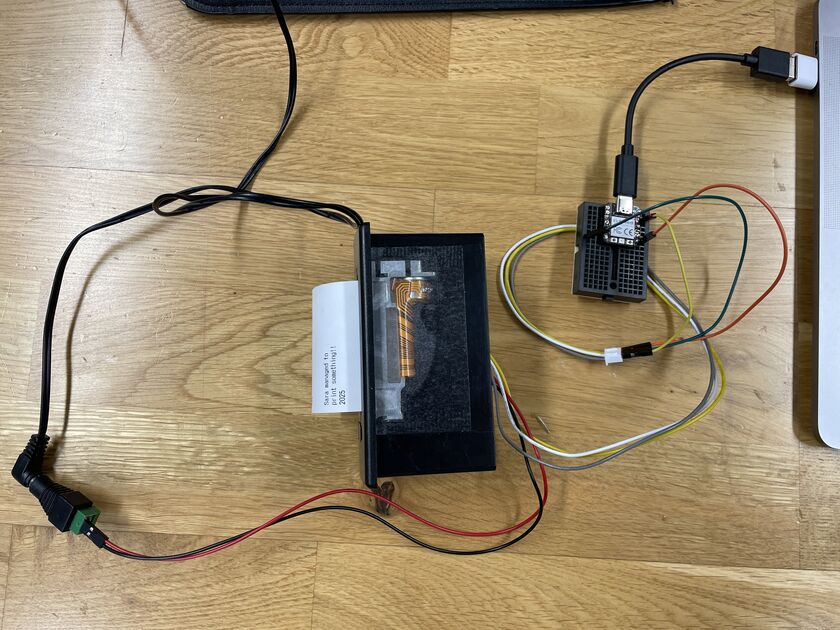
I actually used wall power connector that is rated for 7.5V (with 1.5A), even though the printer has recommended a 2A current, but it works fine, and I think that it is not a problem it works with less (rather than more).
Later in the process, I wanted to use the ESP32 instead of Xiao RP2040, however the Adafruit Thermal printer library does not support ESPs. I therefore pivoted and chose another library called ThermalPrinter. If you want to use it you should download the .zip file and mode and unfold that in the Arduino/library folder. This makes it also easier for me to integrate with fingerprint scanner cause that one only works with ESPs.
Files
Arduino code for testing printer - Adafruit [.ino file]
Arduino code for testing printer - ThermalPrinter [.ino file]
Testing the fingerprint sensor
The Capacitive Fingerprint Sensor I am using is from DF robot. It can store up to 80 fingerprints, and it can detect it from any angle.
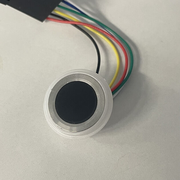
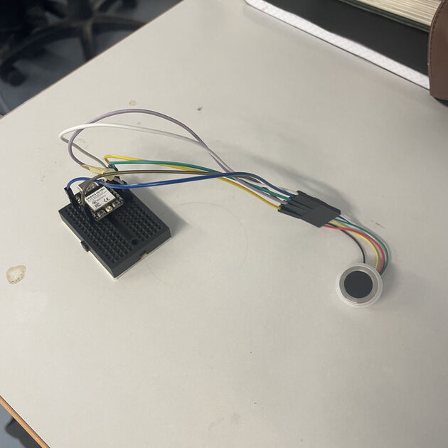
As its visible on the picture below, the cables coming from the sensor had just wire ending. I didn’t want to solder them directly, so before starting to work with the sensor, I wanted to make nice connectors at the end of those cables.
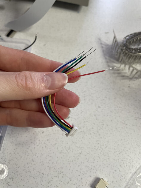
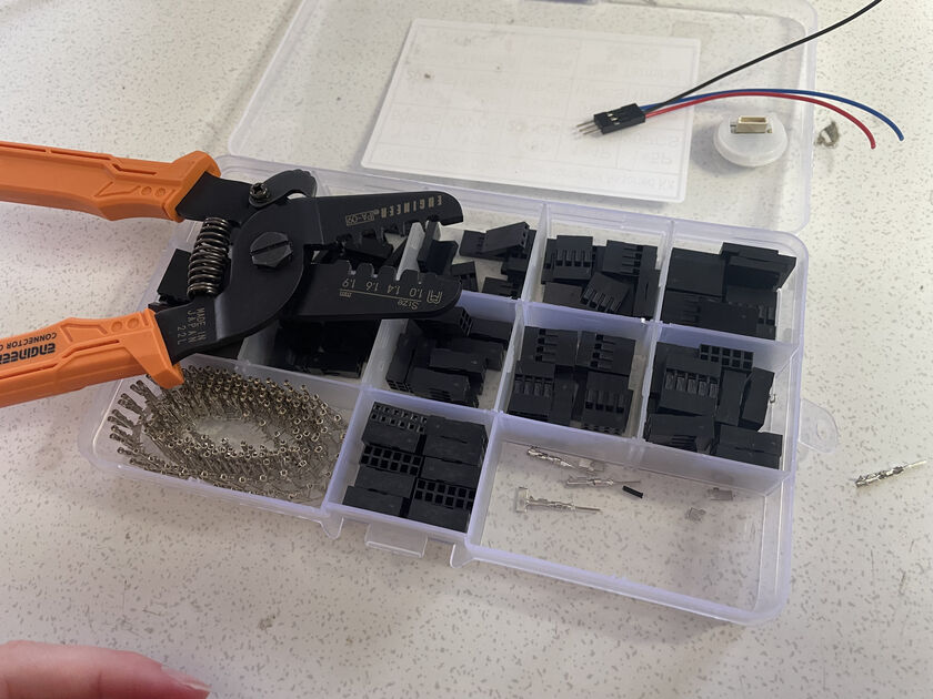
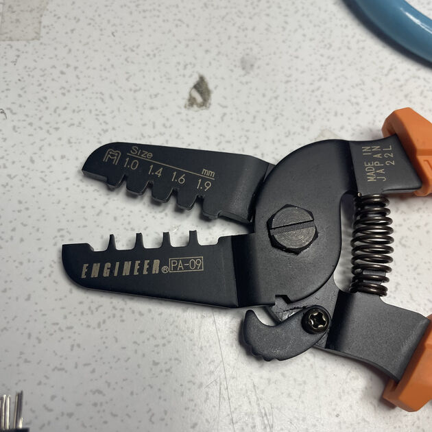
So I used the dupont connector kit with crimping tool.
|
|
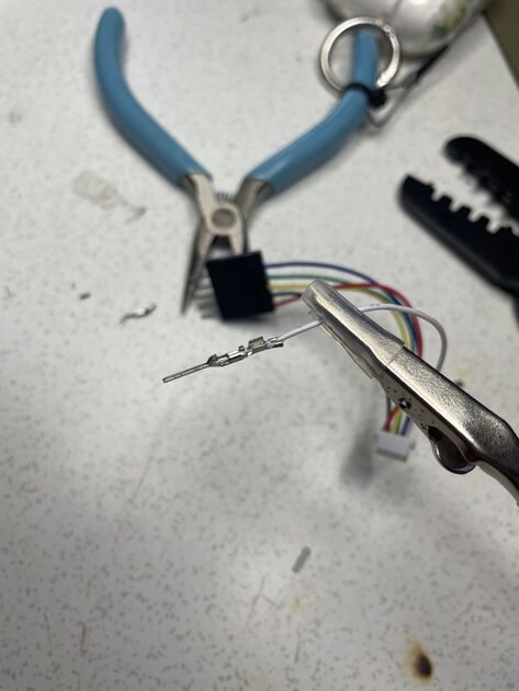
Kris made a nice video explaining how to make these. In short: Cut bit of the cable isolation, crimp the first “wings” around is isolation (picture on the left below), and then crimp the second and third wings (one after another) around the bare wires (picture on the right below). Before I crimp the wings it’s nice to get them closer together with piles. We used the 1.6 mm dent on the crimping tool.
|
|
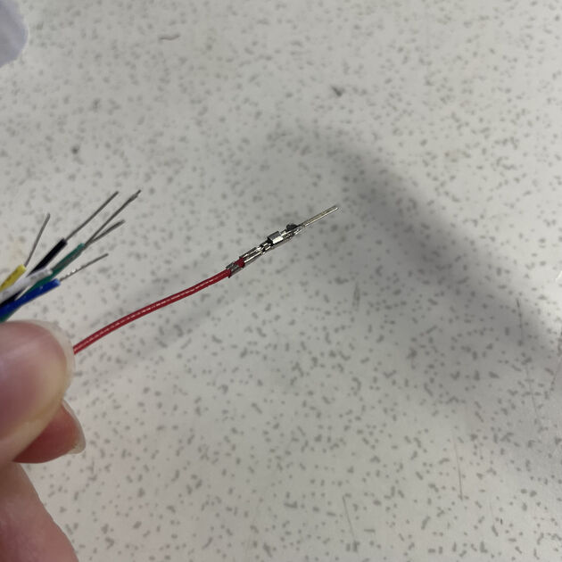
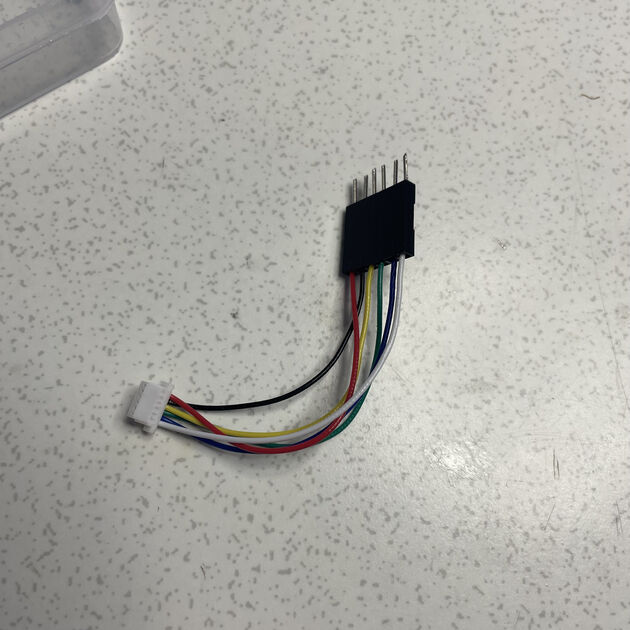
Then you carefully insert the metal part into the bigger plastic hole of the component. As you are inserting the metal part, the plastic sprint will lift. You will hear a little “pop” and see the metal square fit nicely in the hole on the side.
After the connectors were done, it was time to test the fingerprint sensor. I will be using the XIOAO ESP32C3 with it.
The DF robot has quite nice sensor documentation on their wiki, and also an Arduino compatible library on Git - you have to download it, and put it into the Arduino library folder by yourself. There is some sample code and nice diagram of the sensor and its cables in the DF wiki (image below).
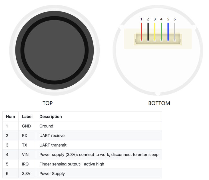
At the bottom of the Git READme it shows the compatibility of this sensor with microcontrollers - there is not RP2040 chip, so I’ll rather use the ESP.
So I connected it according to diagram, compiled and uploaded the example code… And nothing happened.
I saw a video and pictures of someone using the fingerprint sensor, and it seems like there is an LED that is supposed to light up. It did not, and so I (as a weakling) gave up – but turns out that the LED should not be on by default. Then Kris helped me get this working.
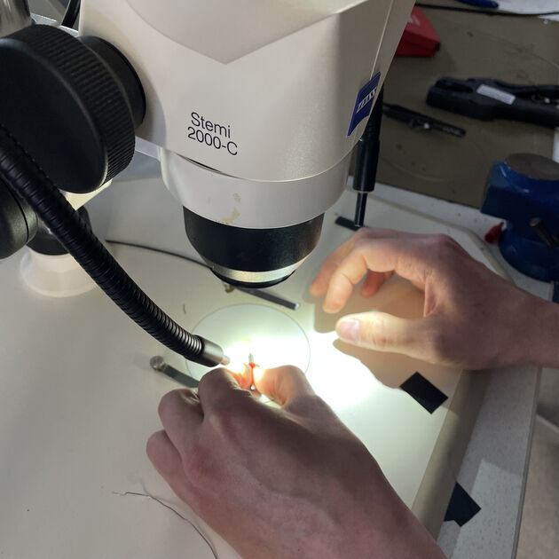
Debugging session ft. Kris
As it was advised in the sensor wiki, we started by switching from software serial to hardware serial. What exactly is the difference? I asked the chat GPT:
Software serial and hardware serial refer to methods of serial communication in microcontrollers.Hardware serial uses dedicated hardware (such as UART peripherals) to handle serial communication, providing reliable, high-speed data transfer with less CPU overhead. This method is typically more robust and efficient.
Software serial, on the other hand, emulates serial communication using software, allowing additional serial ports on pins not dedicated to hardware UART. While it offers flexibility, it can be less reliable and slower, as it relies on the CPU to handle timing and data transmission.
In practice, it meant that we used this:
#include <HardwareSerial.h>

HardwareSerial FPSerial(0);
FPSerial.begin(57600, SERIAL_8N1, -1, -1);
Instead of this:
#include <SoftwareSerial.h>

SoftwareSerial Serial1(2, 3);  //RX, TX
#define FPSerial Serial1
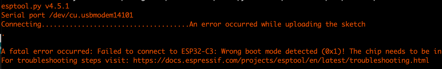
Throughout our debugging session the ESP32 had problems uploading the file (error shown on the image below) – the usual fix of “holding the boot button while connecting the cable" did not work out. We tried different cable, different PCB and later even different computer. It is probably true that my MacBook have this problem more often, but also the Think Pad was quite uncooperative. Later we figured out that if you also press a reset button after you connect the Xiao again, it solves this issue. We wondered whether it might be because it is already using Serial to communicate with the sensor? And by resetting there is the opportunity to upload the new code or something.
Always after we successfully uploaded the new code, we disconnected and reconnected the microcontroller, and just after then opened the serial monitor.
// THIS CODE DOES NOT WORK
// this is the original example from the DFRobot_ID809 library

#include <DFRobot_ID809.h>
#define COLLECT_NUMBER 3
#define IRQ         6  //IRQ pin
#define FPSerial Serial1

DFRobot_ID809 fingerprint;

void setup(){
  /*Init print serial*/
  Serial.begin(9600);
  /*Init FPSerial*/
  FPSerial.begin(115200);
  /*Take FPSerial as communication serial of fingerprint module*/
  fingerprint.begin(FPSerial);
  /*Wait for Serial to open*/
  while(!Serial);
  /*Test whether the device can properly communicate with mainboard
    Return true or false
    */
  while(fingerprint.isConnected() == false){
    Serial.println("Communication with device failed, please check connection");
    /*Get error code information*/
    //desc = fingerprint.getErrorDescription();
    //Serial.println(desc);
    delay(1000);
  }
}

void loop(){
    // rest of code here
}
But that was not the end of our troubles. The Xiao could still not connect to the sensor - one of the cables (ground) connecting the fingerprint scanner was broken! We discovered it by checking all the connections with the multimeter.
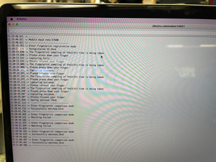
But still no luck running the example code. However, then we tried testing for the baud rate of our sensor (different code from DF wiki). This worked, and showed us a different baud rate (for the serial connection between the Xiao and fingerprint sensor) than in the example code – 57600.
#include <DFRobot_ID809.h>

#define FPSerial Serial1
DFRobot_ID809 fingerprint;

uint32_t ID809_BPS[5] = {9600, 19200, 38400, 57600, 115200};
uint8_t i = 0;

void setup(){
  /*Init print serial port */
  Serial.begin(9600);
  /*Test module baud rate */
  FPSerial.begin(ID809_BPS[i]);
  Serial.print(".");
  while(fingerprint.begin(FPSerial) == false){
    i++;
    FPSerial.begin(ID809_BPS[i]);
    Serial.print(".");
  }
  Serial.println(" ");
}

void loop(){
  Serial.print("Module baud rate:");
  Serial.println(ID809_BPS[i-1]);
  Serial.println("-----------------------------");
  delay(1000);
}
So we tried again the original example code with the updated baud rate -> this did not work, and still said that “not connected”. Weiiird. So we used the base of the code that was supposed to just check the bout rate, and then when it connected to the sensor, we inserted the rest of the code.
What are the changes?
- in the working example, DFRobot_ID809 fingerprint; is declared before HardwareSerial FPSerial(0);
- in the working example we are checking for the correct baud rate in the loop
- there is no while(fingerprint.isConnected() == false) loop. In the working example we are just not checking that.
At the end, we also added pinMode(D0, INPUT_PULLUP); to the setup function – after this, the fingerprint scanner worked as intended. Yay!!
Working example code: Arduino code for testing the fingerprint sensor [.ino file]
Note: We also added to some places delay(100); –> we thought that there might not be enough time for the microcontroller and the fingerprint sensor to connect, and it will then always fail. Not sure if helps, but it probably does not do any damage.
Integrating the printer with fingerprint sensor
Integration has been a little tricky, because in the sections above I was using XIAO RP2040 for the printer and XIAO ESP32C3 for the fingerprint scanner, and those were the only ones that worked for the given Arduino libraries. So I switches the printer library to a new one, called Tprinter, as this one also supported ESPs.
After a bit of fiddling and combining the code, I managed! Now when one adds a new fingerprint to the database, an “angelic” name will be assigned to it. Then later when it is scanned again, a message including the angelic name is printed.
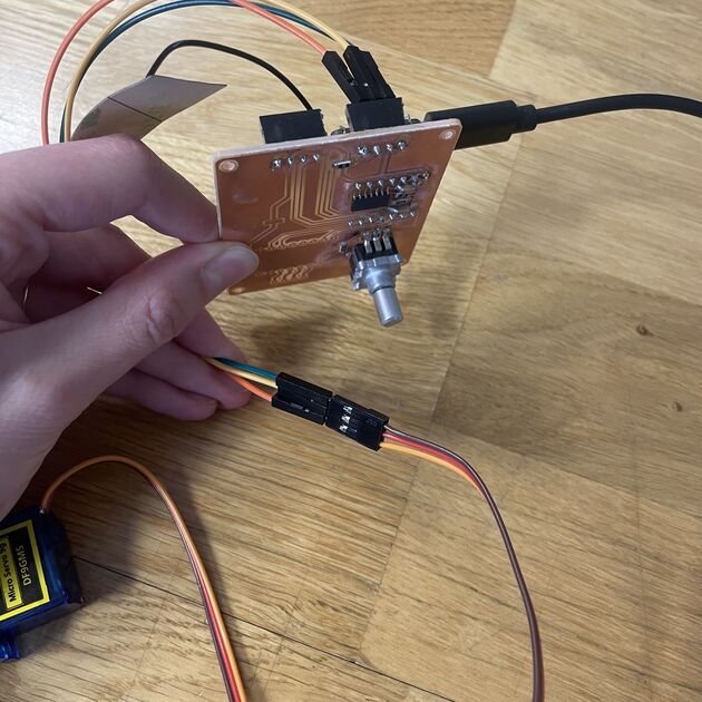
Below is the test setup, I wanted to try if everything works with cables before designing a board.
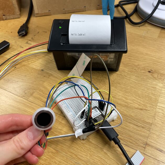
In the video below, the first time I attempted to scan my fingerprint, the scanner flashed red, which mean that the scanner could not recognize my fingerprint -> I just touch the scanner in an odd angle, but it could also mean that the fingerprint is not in the database. Then I tried again and again and the scanner flashed green, and the printer printed a little greeting message for me, Zadkiel :)
Arduino code that integrates the fingerprint scanner with the printer [.ino file]
Now it’s time to make a proper PCB board!
Blinking mechanism
I would like the Oracle to blink. When it wakes up, and sometimes just like that. It could be a cool effect of interaction with the surrounding.
But how does the blinking work? I started the research with looking up the blinking in dolls, the ones that close their eyes when laying down.

They work with gravity, e.g. there is a little weight that want’s to be
Good explanation and showcase of this is in this YouTube video.
The above is not really what I am looking for. I would like to open and close the eyes with a servo motor, not by moving the Oracle. It was honestly quite difficult to just start 3D modelling my version, I found it challenging to imagine how to attach the eye and the eyelids. So I looked up more blinking doll eyes / puppet eyes, and found some 3D models which I have printed. First one from here and second one from here.
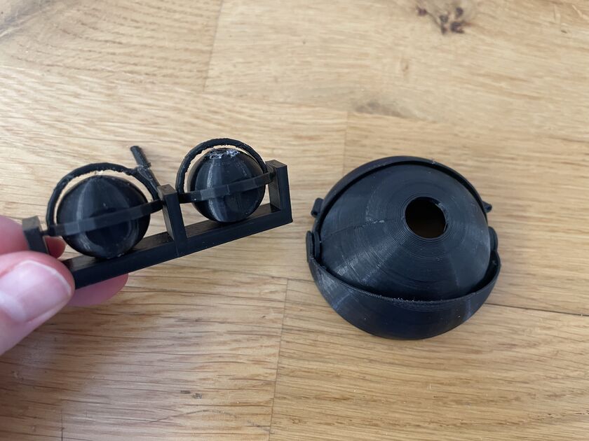
I quite liked how the eyelid of the first model worked. It is attached from sides to something fixed, and I think I could use a hard-wire to move it up and down -> Let’s try this idea, and see how it goes, iterate on it.
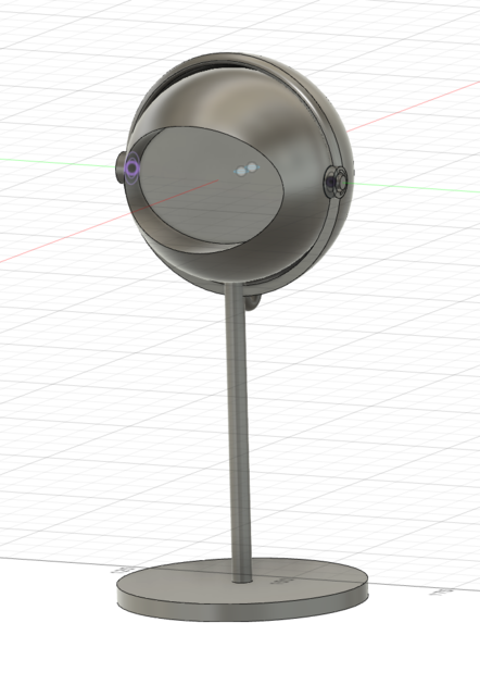
I used Fusion 360 to do the first model, which I printed and then I iterated on that. The first model was too tight, then too loose, but finally I managed to make is just about the right tension.
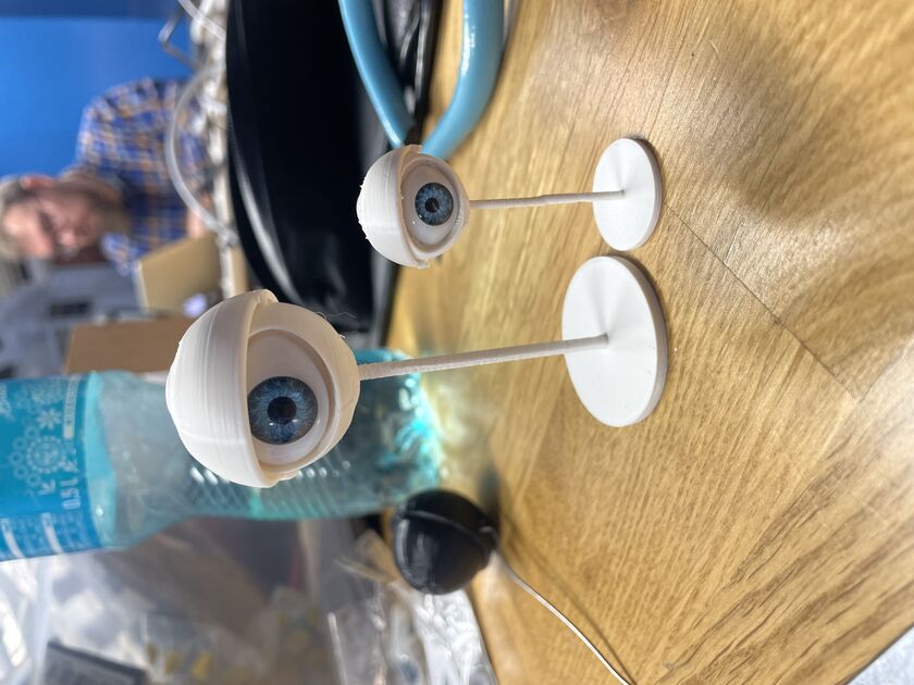
I added a small loop on the back, so an aluminum string could be attached. Then the eye started working like a puppet :)
I shall now try to work on connecting them to servo motors, so the eyes can blink automatically. I can also imagine they eyes itself moving horizontally, but maybe it’s not so much added value. I’ll stick with solely blinking for now.
The Fusion 360 file from this part: [Eye .f3d file]
Servo
To control the blinking mechanism, I would like to use some servo motors. I am using the Xiao Seed boards (either RP2040 or the ESP32C3) for their size and functionality. They have the 5V power pin, but the working voltage of the MCU is 3.3V. That is insufficient to use for the Servo motors, as they also need 5V for their data pin (I/O on Xiao)*. So it’s necessary to use the level shifter, which we shift the signal from I/O pins on Xiao (which are from 0V - 3.3V) to supported range of the servo (0V - 5V).
*here is a datasheet of one of the servos. Here is says that the operating voltage is 3.5V-6V. The operating voltage of the Xiao is 3.3v +- 0.5V, so when I tested the servo without the level shifter it worked, however as I plan to add multiple sensors there, the voltage on the I/O pins might drop to 3.3V, and that won’t be sufficient. It’s better to use the level shifter, and to have the 5V guaranteed.
Kris have worked on a similar project that included a level shifter, so to speed things up we just milled the same board that Kris had designed. The project RotoStage, made by Krisjanis Rijnieks, including the original files.
We milled the board using the new fancy milling machine (Bungard). Life is good.
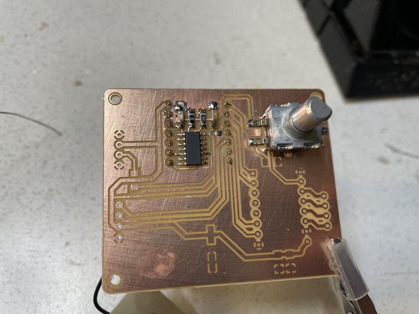
I soldered the necessary components, though I accidentally first soldered the potentiometer upside down (picture below), but I managed to fix the mistake using desoldering braid.
To program the servo one can use some Arduino servo motor library, or program the servo motor directly using the PWM (pulse width modulation). Why does servo motor need PWM? I asked the Chat GPT and this is the answer:
Servo motors use PWM because it provides precise, stable, and efficient control. PWM signals are digital, making them resistant to noise and easier to generate with microcontrollers. They also reduce energy loss by delivering power in pulses rather than continuously. Additionally, most servo motors are designed to decode PWM signals, making it the industry standard for control.
In PWM there is this concept called the duty cycle, which determines the “angle” of the servo, e.g. how much it’s going to rotate. It is the fraction of period in which the pulse is on (basically the pulse width). Most servos have the period 3000us (min duty cycle 500us and max duty cycle 2500us), though seem like the newer servos don’t need the downtime to be complemented by the uptime, meaning that the sum of pulse width does not need to be complemented by downtime to total one period, there just needs to be some downtime - source.
Detail of connections:
Kris and I made a little program to determine the duty cycle of unknown servo. There is also a code to control the servo with a potentiometer - so as you rotate the potentiometer, the servo will move as well.
Code from this part: [.zip file]
Controlling blinking with servo motors
Now it’s time to connect the servo with the blinking mechanism! I did a little test, just with octopus hand supports:
There was a brainstorming session with Kris, we compared some concepts:
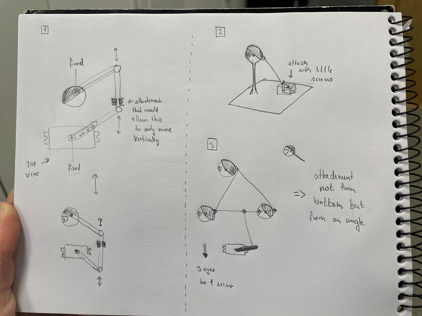
We decided that the servos should be in the “head” of the Oracle, as this will make the whole structure more robust and the blinking more predictable, so just the cables are going to the middle “rod”. Kris suggested making the servos communicate through I2C, but I believe that there are still enough pins on the Xiao, and we can just connect the digital pins “directly” (through the level shifter though). One problem might be that there might not be enough current to power all the servos, but if that’s shows to be a problem, we can add an external power supply later. Lets made the servos modular.
Based on this, I made a model that will somewhat firmly attach the servo to (first one, and then) multiple eyes.
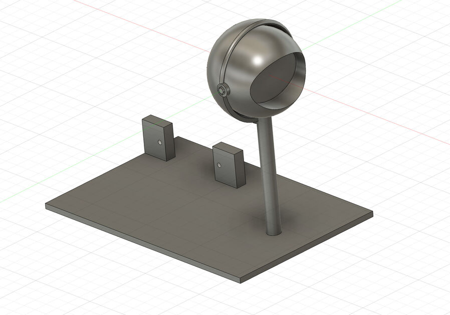
Model for this part: [.f3d file]
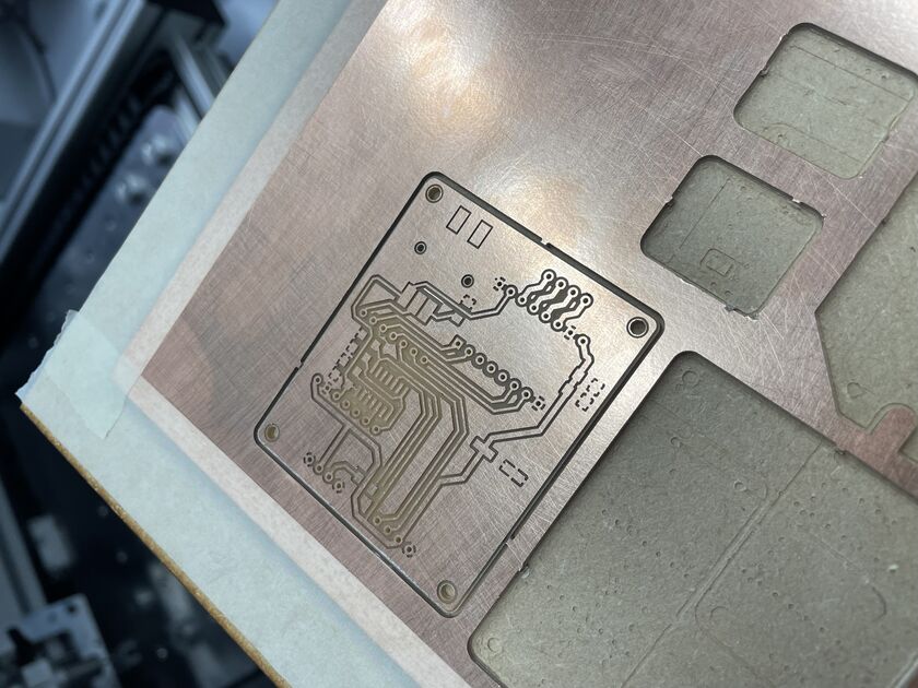
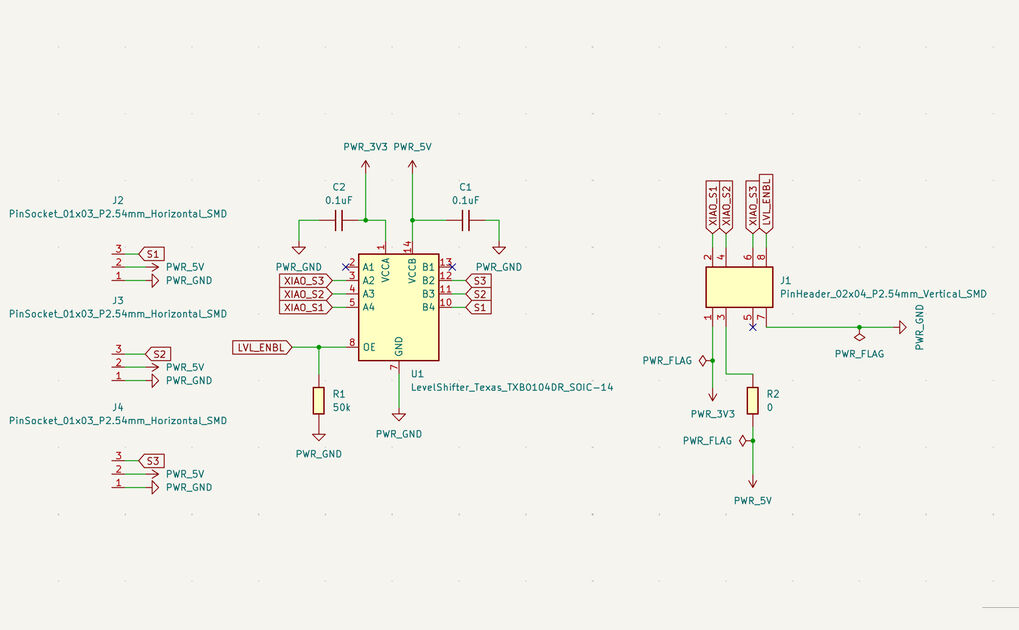
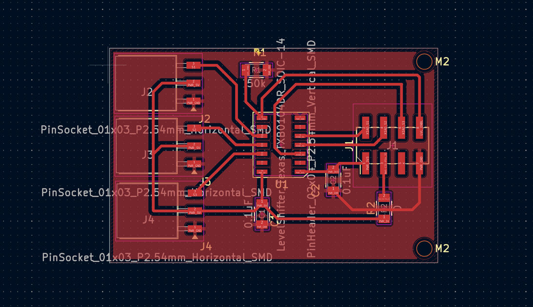
New original PCB to control multiple servos
Based on the PCB made by Kris, I designed my own PCB that can support 3 servo motors. It is a separate PCB from the control of the printer and fingerprint scanner, so the whole design is a bit more modular.
When I was making a PCB, I wished to have 2 different KiCad windows open (like 2 different designs). However, that does not seem possible within the app, so from the terminal I launched a new instance of KiCad with open -n /Applications/KiCad/KiCad.app (explanation here, I use MacBook).
The PCB has holes corners for M2 screws, so the board can be firmly attached to the base of the Oracle.
|
|
KiCad files for this part: [files]
Video from milling:
Components soldered:
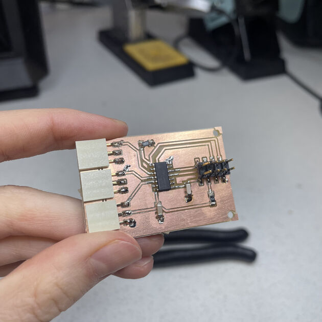
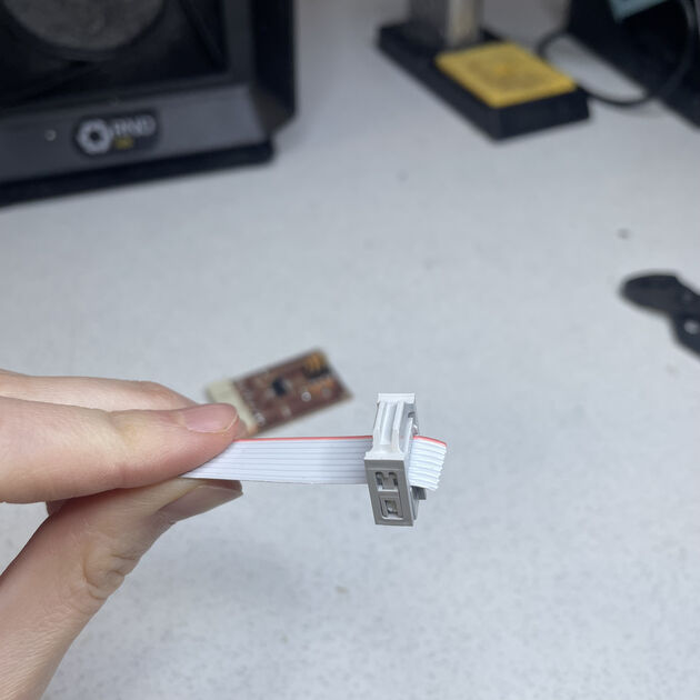
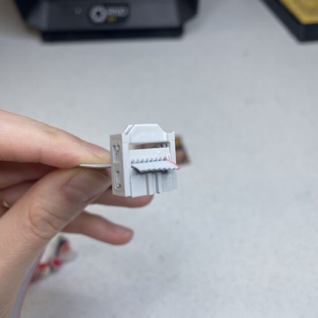
I used these “bus” cables to communicate with the microcontroller, they are more firmly attached, and they stick together making is a better and neater design choice. Kris also remarked that you can add multiple “stops” on the cables, so then you can send information on the same line for multiple devices. It was interesting to attach the pin holed to the cable (and then to fix it in place with an extra plastic cover).
|
|
Main PCB
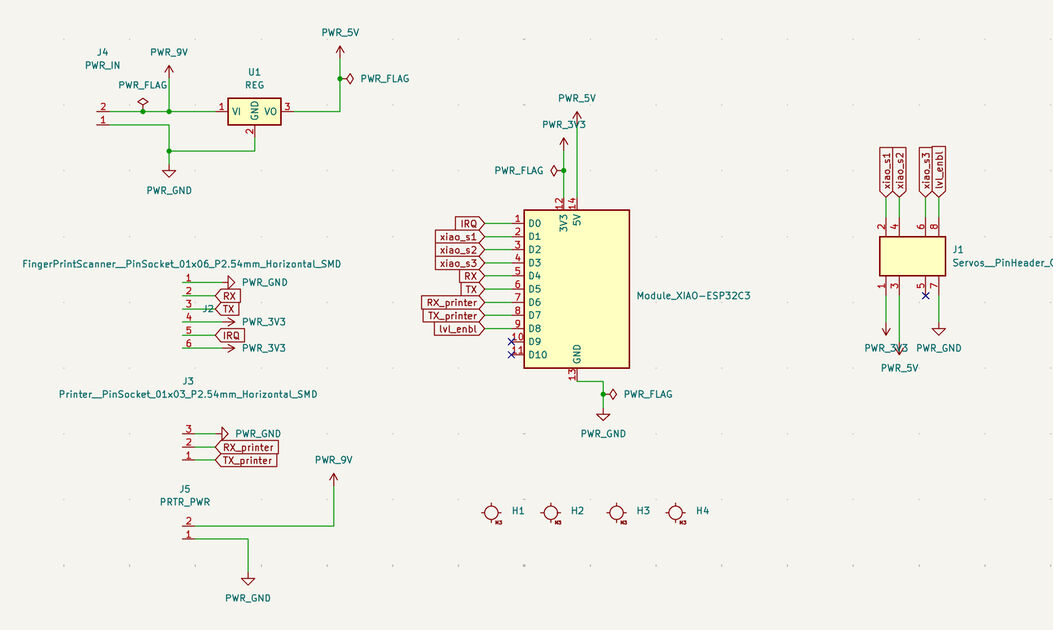
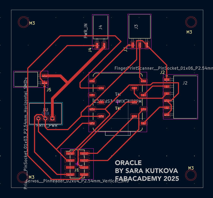
Is it now time to make a main PCB that would connect the servo PCB and also could connect the Xiao to the printer and fingerprint scanner.
I started with the KiCAD:
|
|
Files for this part: [GitLab folder]
We then milled the PCB.
The end mill we wanted to use originally was broken, and during our milling we also broke one (we checked with the microscope). The paths turned out great, however you can notice it a bit on the engraved text. Maybe next time I could use the KiCAD font as that if vector format and then the engraving would look different.
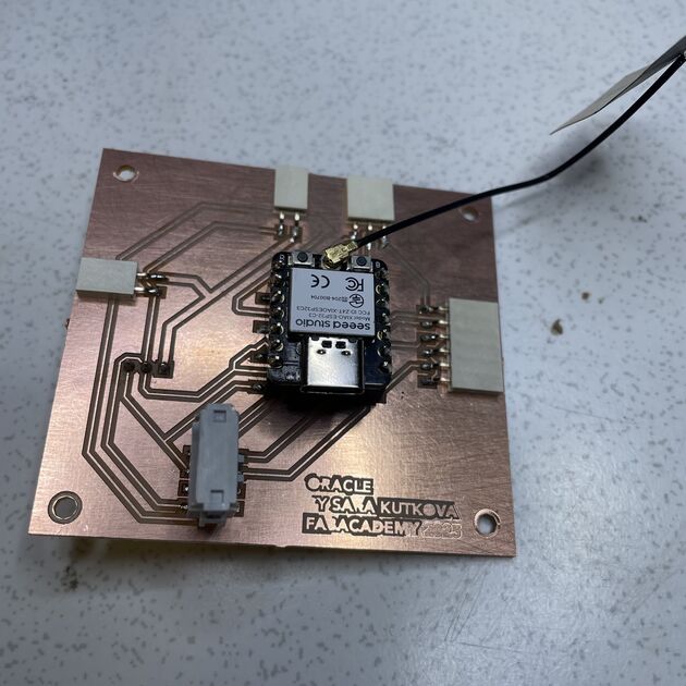
The milled PCB. Nice and shiny.
I then soldered the components on the PCB. You can notice that one component is from the other side, that is the DC/DC voltage converter - TSR 1-2450E, changing the input voltage from 7.5V to 5V.
I then connected it with the Servo motors PCB.
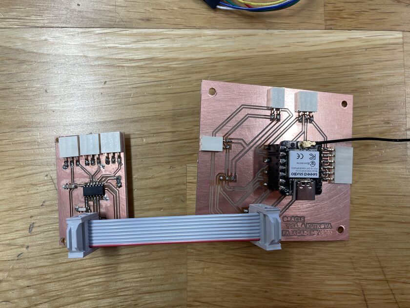
And tested it out!
At first the printer and fingerprint scanner were working well, but the servos did not work.
System integration
This part is documented in the system integration week.
But what I took to heart from the system Integration Global Lecture is I want to be able to shake the oracle without breaking, so I want to attach all the components securely.
First draft of the casing:
Attaching the components:
|
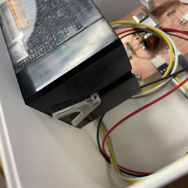
|
I designed the case in Fusion 360, and decided to 3D print it for the convenience, and also because I wanted to have the insides specifically adjusted for the electronics. Looking back I could maybe make the box from other material (acrylic and laser cut?) and only 3D print the bottom of the box, which could I later glue on the bottom of the laser cut box.
The problem with printing such a large surface is that the as the PLA cools down, the part touching the print bed bends - it is quite visible on my box that one corner is bent upwards.
The other problem with a big 3D printed object is that when the print fails, there is a lot of waste. Not ideal! My print failed 2 times before it was finally printed correctly.
The half circles for the “head” have a very ugly finish. I always planed to have the fabric over them, so it was not a big deal, but I mush admit that the ugly finish did bother me.
|
|
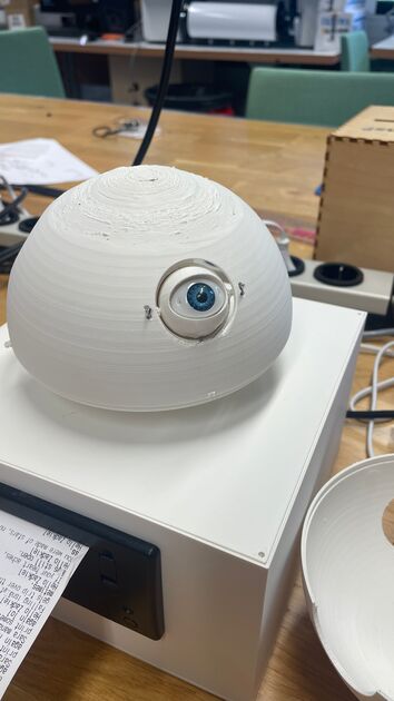
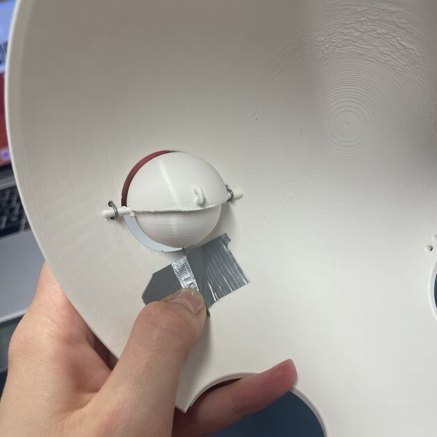
Bellow is the attachment of the eyes from the inside. At first, I attached them straight with some duct tape to see the proper position, but I later secured them with hot glue.
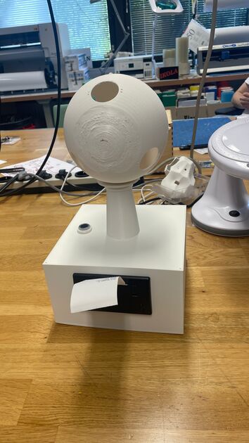
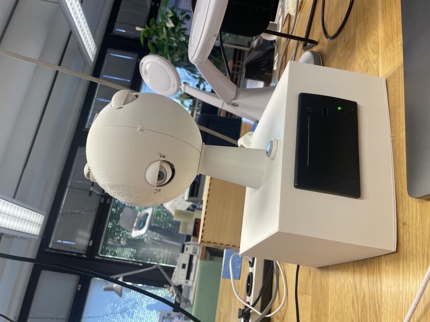
The case without fabric sleeve over it. Hope its creepy enough.
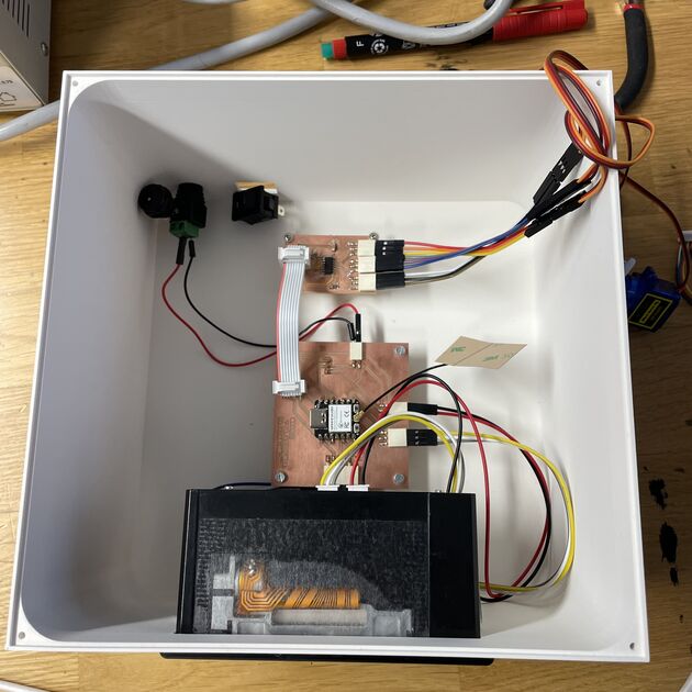
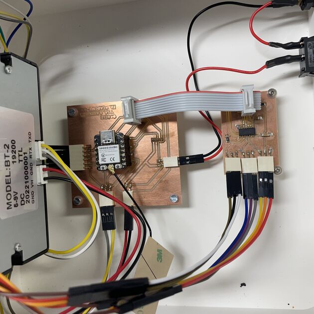
Detailed picture of the electronics inside :)
Backend code adjustments
Previously I wrote about integrating the fingerprint scanner with the printer. I now waned to polish the prophecy generating and the moving of the servo motors for the eye blinking.
The prophecies sometimes included some strange characters in words, and after some checking it seemed like the printer library I was using could not properly parse apostrophes and hyphens (and it was mistaking them for something else). Because the time was running out, I did a simple fix -> asked Chat GPT to just rewrite all the prophecies to not include any apostrophes and hyphens, so for example it would expand all the “don’t” to “do not” and so on. I also added some space before the prophecy and after it, so you would get a nice little paper with it.
myPrinter.feed(6);
myPrinter.print("Hello ");
myPrinter.println(angelNames[ret]);
myPrinter.println(angelQuotes[random(0, 802)]);
myPrinter.feed(6);
For the eye blinking, I wanted every “stepper motor” to randomly “blink” at some point between 3 seconds and 5 minutes. The code needed to be non-blocking, so the servo movement would not interfere with the printer and fingerprint scanner.
I usually don’t do this much with programming, but I got lazy and asked ChatGPT for some code - and it worked surprisingly well. Of course, it did not produce working code, but the logic was there, and I tweaked and integrated it into my code - the main problem was that the pins were named D1, D2 and D3, and so I declared that separately. But otherwise the solution was very clever!
Click here for the whole conversation with the chatbot.
The final integrated code is in the .zip file that can be downloaded at the bottom of this page. There I also included the prophecy.h file that includes all the prophecies.
Sewing and embroidery
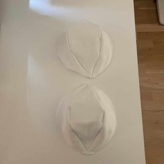
I wanted to make a fabric “sleeve” for the oracle head on which I could embroider eyes and attach some more plastic ones - play with the design. As I wanted to still be able to access the “inside” (the servo motors), it would need to be made from 2 halves.
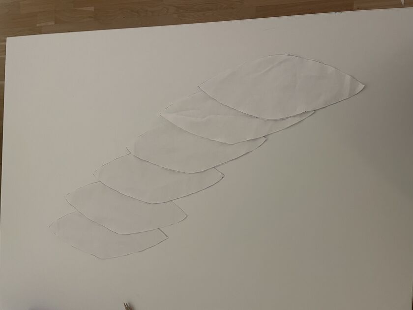
I found some ball pattern tutorial online which I followed. I sewed the 2 halves separately using the Singer Traditional sewing machine.
|
|
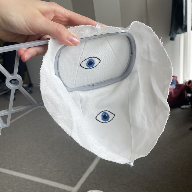
I made some embroidered eyes - details about embroidery can be found in the Wildcard week.
I wanted to make an attachment mechanism for the two head halves - although the 3D printed parts snapped together nicely, I also wanted the fabrics to help to hold the head together. I chose to use the Velcro (or the non-trademarked name -> hook-and-loop fasteners). It folds well, but I am not sure if it looks that pretty. Maybe I could have rather made sure the electronics (blinking mechanism) works well, and then sew the two halves together by hand?
Final touches
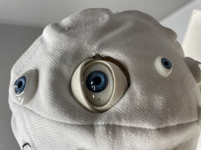
At the end I attached more plastic eyes, and did a little photoshoot.
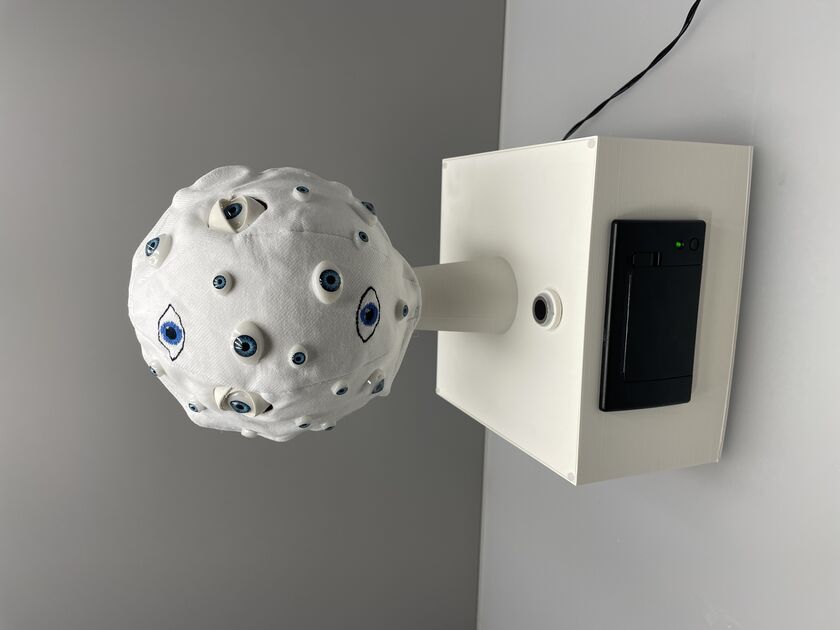
Sample prophecy. My angelic name is Zadkiel.

Files
All the relevant (and final) final project files need to be hosted in my FabAcademy repo, so I made them into one .zip file -> download here.