Week 7: Computer-Controlled Machining
Group Assignment
The page describing the group assignment for this week (runout, alignment, fixturing, speeds, feeds, materials, and toolpaths for our machine) can be found here.
Introduction
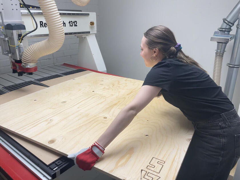
This week we are working with the CNC (computer numerical control) milling machine to make a bigger piece (such a table or shelf). I haven’t worked with the CNC milling machine before, so this was the most challenging week so far. We have two such machines in lab - big and small one. I will be talking only about the big one, the Recontech 1312 milling machine.

|
|
As the whole process took some time, I divided the documentation into several parts:
- Design
- Preparation of the machine + software + safety
- Test mill
- Milling process + cleaning
- Post-processing the wood
- Applying protective coat
- Assembling
The whole process is rather complicated. I tried to note the things I found important and interesting, but the more precise documentation can be found at the CNC milling wiki page, and even I will be referring to it shall I use the machine again.
1. Design
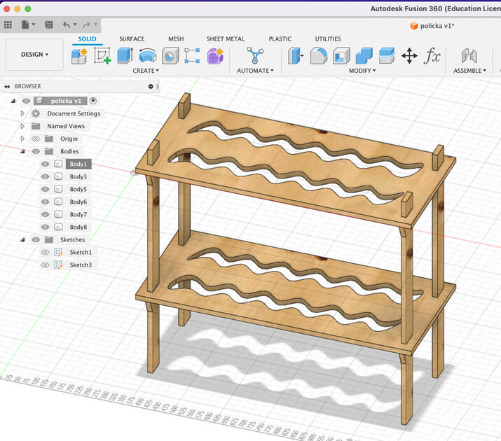
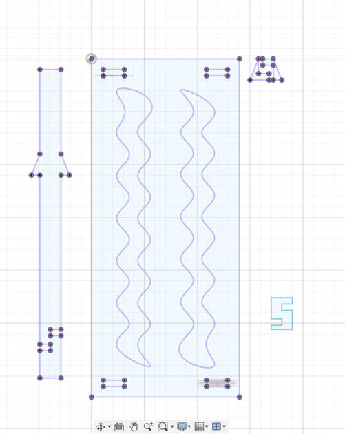
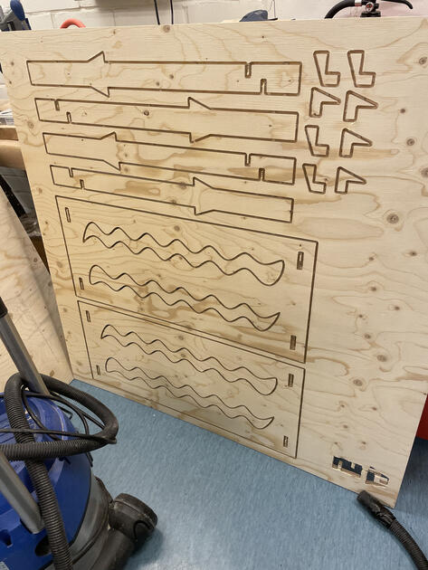
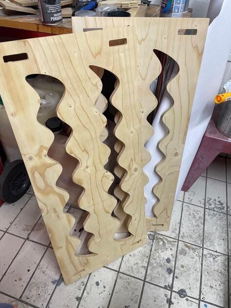
I wanted to make something that I actually need and would use. After a bit of brainstorming, I set on making a shelf for clothes. I wanted a nice, simple and fun design, so I added waves there.
Download the 2D sketch used for milling - [.dxf file]
Download the 3D design - [.f3d file]
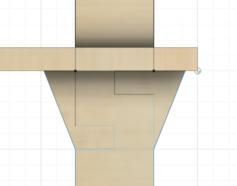
I wanted to make the assembling nice and simple, so I designed the legs in a way that you can insert the bottom shelf, then add the stoppers and then the top shelf. I was quite worried that the shelf will be too wobbly (and how it will look like in general), so I made a smaller (scaled to 20% of the original size) laser cut version using 3 mm thick wood - documented the process in the Week 3 documentation page. The results were that if the joints are tight (that you need a bit of force to get them in the place), the self is not wobbly. However, now the concern is if it’s going to stand straight.
The other idea I had was to add a string “X” to the back of the shelf to (made out of nylon or some other durable material) to prevent the wobbling. But for now let’s make the shelf, and we will fix these “wobbliness” issues if it arises.
|
|
2. Preparation of the machine
After you have your files ready (but before you can start milling), you should prepare the CNC machine.
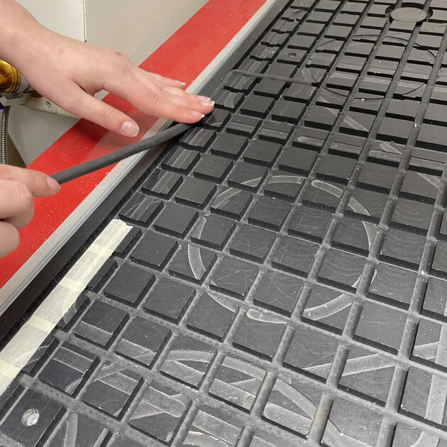
First start with sealing the bed. When the machine is milling, it is physically carving into the wood. We need to make sure that the wood won’t move - otherwise our design could be ruined. There are few options how to do this:
- We could use multiple clamps and attach the wood to the machine. This works, however one needs to be extremely careful to not make the tip of milling machine to hit the clamp, as this could destroy the tip, maybe damage the machine, or it can even be a fire hazard.
- We could use the vacuum bed that sucks the wood (using the breathable layer).
There are some other options how to secure the wood on the bed, for example glue, weights or screwing it to the edge, but I found the two methods above the most common.
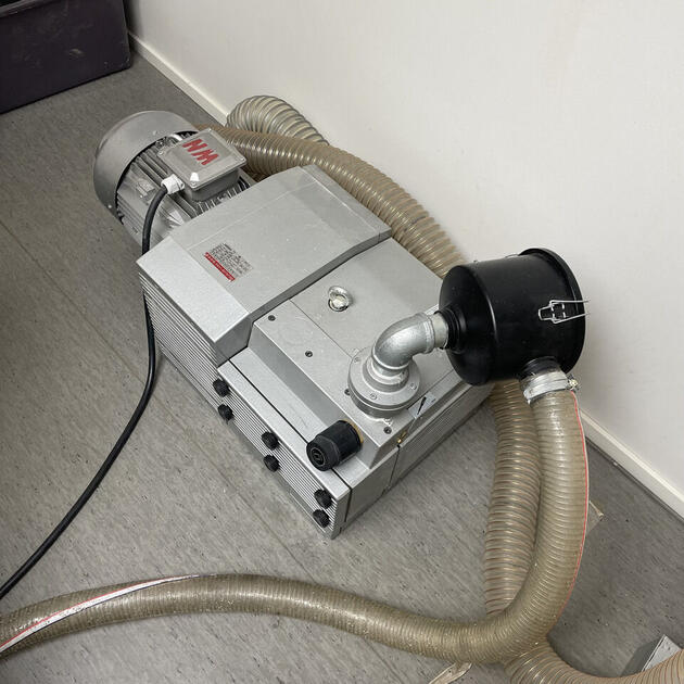
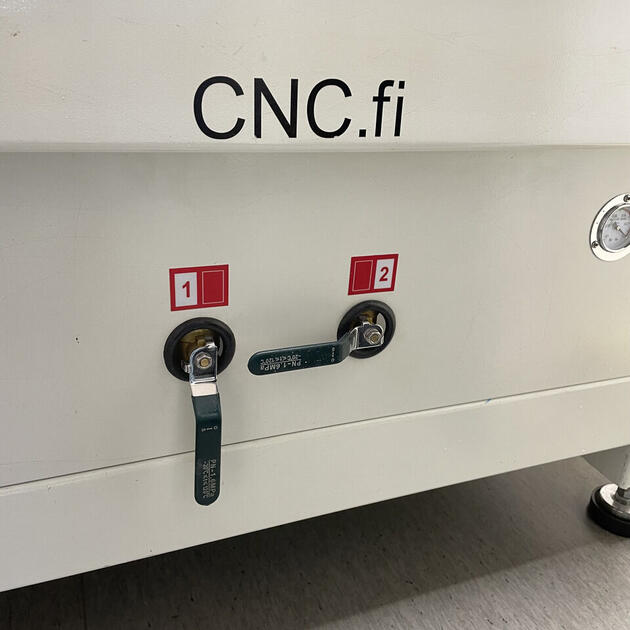
After the bed is sealed, we can check whether the suction is good enough. We can turn on the vacuum by opening the vacuum valves, and then turning it on (as seen on Fig 8 and Fig 13).
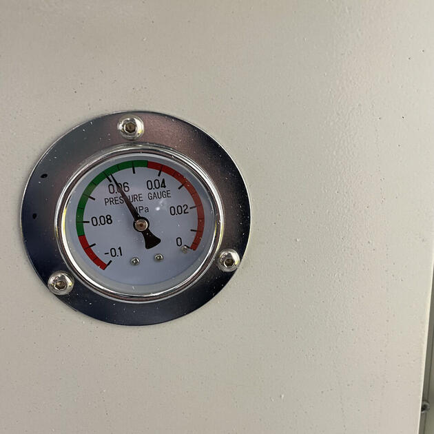
Sometimes vacuum is not enough - e.g it is not capable to hold the piece of wood in place. We can test this by trying to move the wood, or we can also check the suction pressure indicator next to the pressure valves in the front of the machine. If the vacuum works as intended, the indicator in the pressure gauge should be in the green area as shown in the picture below.
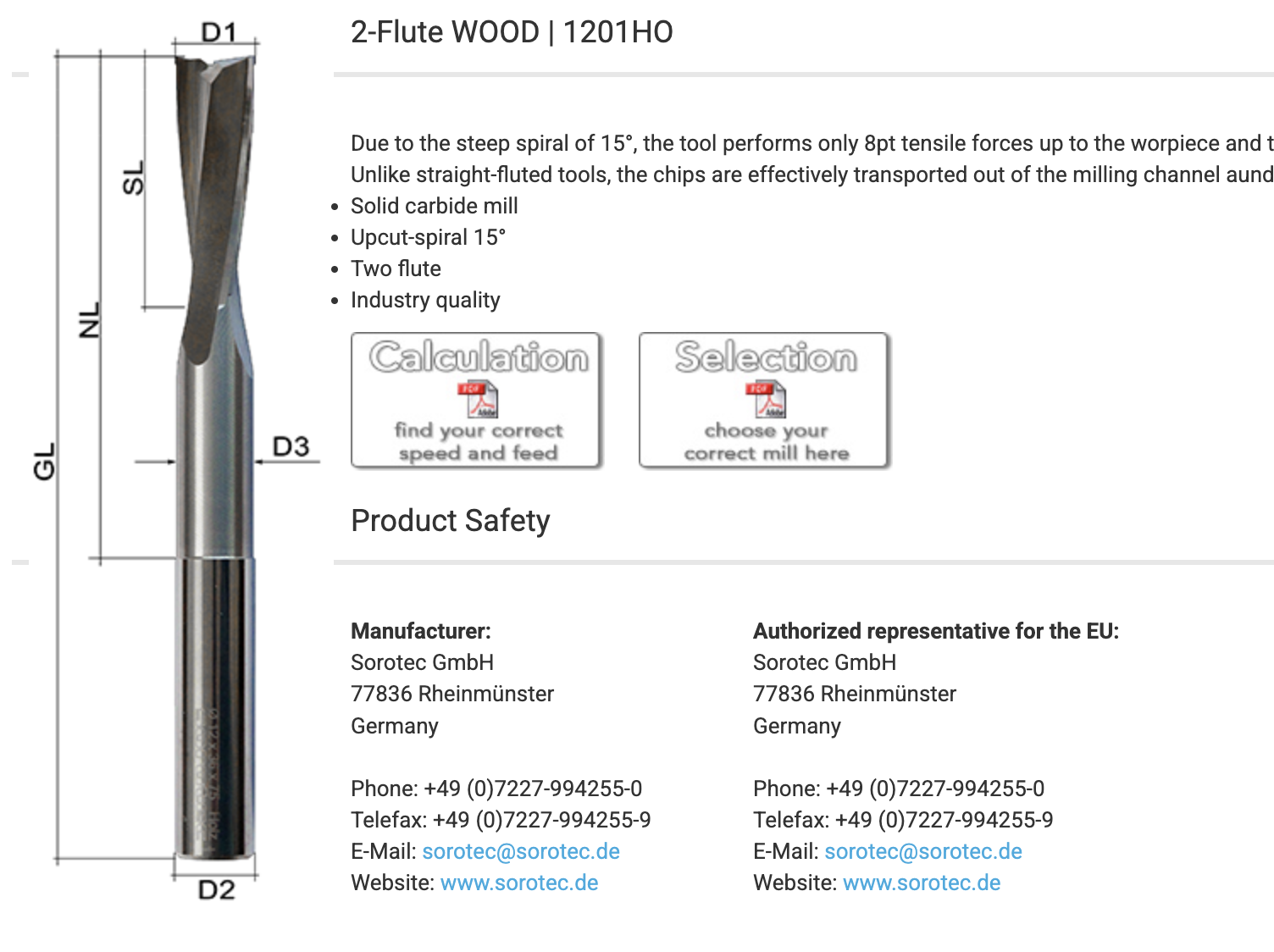
Next we should insert the correct milling tool. The tools vary, depending on how precise we want our cut to be (generally smaller the tool, the longer the milling process will take, but it can capture more detail), if it’s an “upcut” or “downcut”. I asked ChatGPT about the difference between of those two:
The terms “upcut” and “downcut” refer to the direction of the spiral or helix of the flutes on a milling cutter. Here’s how they differ in the milling process:
- Upcut Milling Cutter: An upcut milling cutter, also known as an upcut spiral router bit, has flutes that spiral in an upward direction towards the top of the cutter. This means that during the milling process, the cutter pulls the chips or material upward and away from the workpiece. Upcut milling is commonly used in operations where chip evacuation is important, as it helps to clear the chips from the cutting area, preventing clogging and improving the surface finish. However, it may result in slightly rougher edges on the top surface of the workpiece.
- Downcut Milling Cutter: A downcut milling cutter, also known as a downcut spiral router bit, has flutes that spiral in a downward direction towards the bottom of the cutter. In this case, the cutter pushes the chips or material downwards into the workpiece. Downcut milling is often used in applications where minimizing chip-out or splintering on the top surface of the workpiece is important, such as when cutting delicate or thin materials. It provides a cleaner top surface but may have slightly reduced chip evacuation capabilities compared to upcut milling.
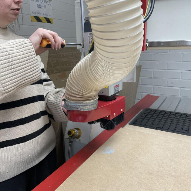
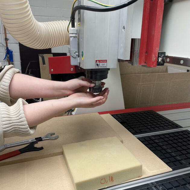
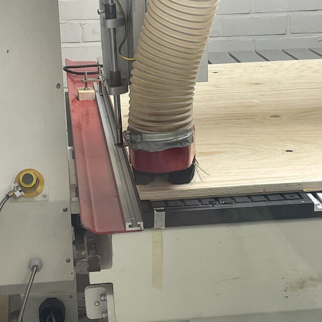
Before we continue, remove the dust shoe (on picture above), so we can see better, and secure the toolholder properly. Attach it back after we are done changing the tool.
Depending on the tool, we pick an appropriate toolholder.
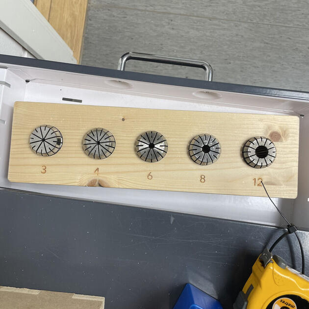
When changing the toolholder, one need to be careful and put a soft cushion bellow it, in case that the toolholder fall (so it doesn’t break). Be sure to tighten the tool properly!! I need to use all my strength with my spaghetti arms to make sure it is secured properly. Also use appropriate tools such as two wrenches to tighten/release it. If the tool is wobbly, it can release itself a bit and can ruin your design, or/and damage the machine at worst.
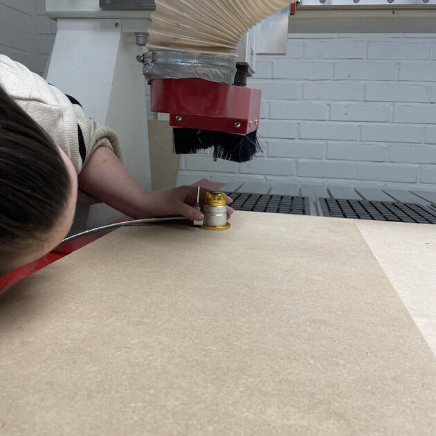
Next thing do is to calibrate the z-axis. There is a tool for this (left side of the machine, attached by magnet) as seen on the picture bellow. Align it with the milling tool and then press the only Finnish button the whole software. The vacuum needs to be on for this step, as it will be on during actual milling, and it will suck in the wood a bit.
The software
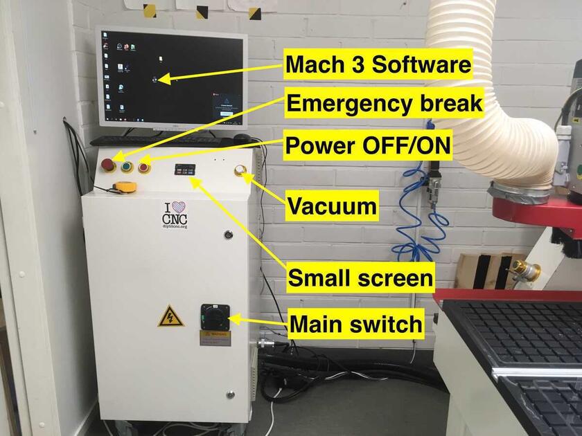
First, let’s get familiar with the controlling panel. In the Figure bellow, we can see the main computer in the CNC room, which is the same as the one outside the room (the displays literally mirror the same things, so its like one computer, two displays). It has both VCarve and a CNC machine software. On the panel we can notice the main switch (powering the room), vacuum button (which turns on and off the vacuum), and the power button for the CNC machine.
I prepared my design in a .dxf file, and then created the toolpath in the VCarve software. This can however be done using other software as well, for example using a Fusion 360 plugin, I just felt that people at the lab are most familiar with VCarve and therefore can help me better if I ran into some problems.
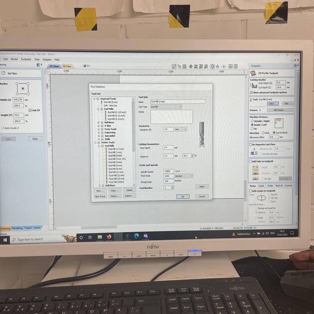
In the VCarve, it is important to add the correct tools, specify whether it’s going to be upcut or downcut, and add tabs.
First choose the outline tool, next specify the cut depth (the thickness of the wood). When choosing the tool, one needs to calculate the feed rate. The equation is:
Feedrate = Number of Flutes * Tooth feed * RPM
To better understand this equation, I asked the ChatGPT, and apparently:
The feed rate is speed at which the cutting tool moves along the workpiece.
The number of flutes is the number of cutting edges or flutes on the milling tool. It can be different for each tool, and we should check the tool chart for this information (or just count them on the specific tool).
The tooth feed is a distance the cutting tool advances along the workpiece with each revolution.
The RPM (revolutions per minute), or spindle speed is the rotational speed of the milling tool.
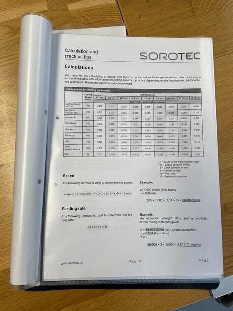
I think I was using the 3mm tool (2 flutes). We received a soft wood, so the according to the table bellow, the tooth rate is 0.035. The machine can do 20000 RPM, but for safety we only use 16000RPM. Then my feed rate is:
Number of Flutes * Tooth feed * RPM = 2 * 0.035 * 16000 = 1120 mm/min
The plunge rate should be 1/4 of the feed rate, so 1120/4=280 mm/min for me.
Next, one should add tabs. Tabs are thin pieces on wood that we leave in when milling a path, so that the piece we are cutting is not going to move in respect to the original bigger piece. If they are not there, the suction might not be strong enough and as the milling is progressing the tool could push and therefore move the freshly cut piece, which could be then ruined when the tool is milling something close by.
Before exporting, we can then see the preview of the toolpath to check if it looks as expected.
After we save the toolpaths, we can load it to the CNC machine software (Match 3?), and start the milling process (at this point all the preparations need to be done, and the machine is ready with the vacuum on, door closed and no one in the room with the CNC).
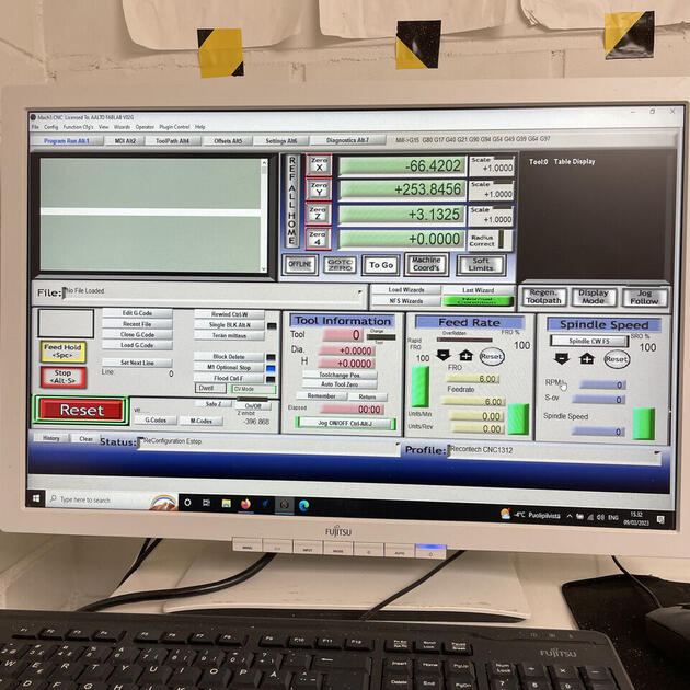
This is only an outline on what was happening, the deeper dive in how to use the software can be found in the wiki page.
Safety
According to Neil, this is the most dangerous machine we get to use in the Digital Fabrication course. I paid extra attention to the safety measures, and made sure not to hurt myself, people around me and the machine itself (in this order). I really like that in our lab the setup is that the machine doesn’t work (does not rotate) while the door is open. Therefore, I always made sure that the door is open while I’m close to it.
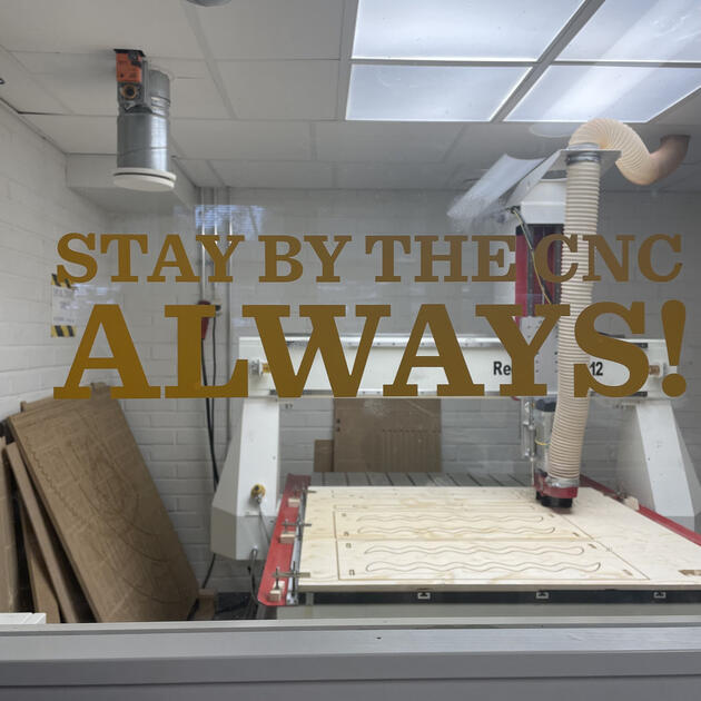
Another thing is that one should always stay by the CNC machine while its milling. It is quite boring, but honestly a very important as things can get bad very quickly, and we want to minimize the damage done. We were advised to listen to CNC, and stop it if its making some weird noises. I think it’s good advice for more experienced users of CNC, because I felt that all the noises that machine made were rather weird / too loud etc. Nothing bad happened during my cuts, so I still don’t know how “crying CNC” sounds like.
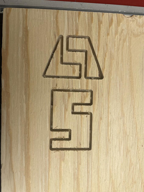
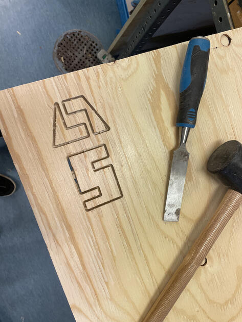
3. Test mill
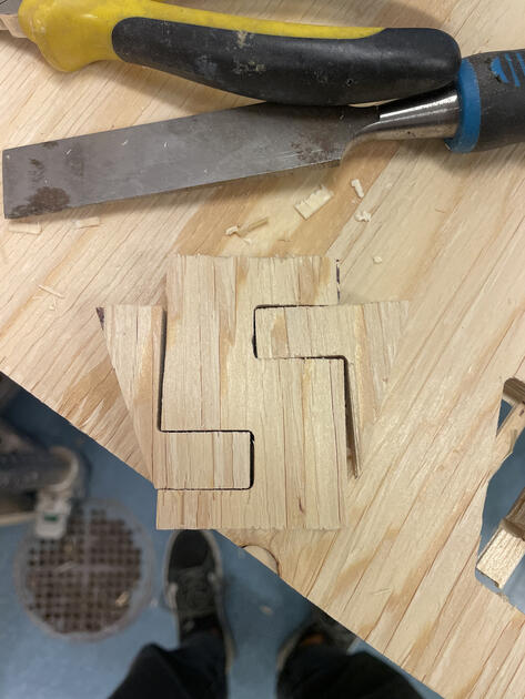
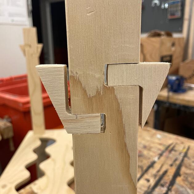
I wanted to try milling some smaller pieces to get myself familiar with the process, and to see if the joints I design would hold together nicely.
|
|
I highly recommend to always wear gloves when working with wood, not just because you have a better grip, but it can also save you from some unpleasant splinters.
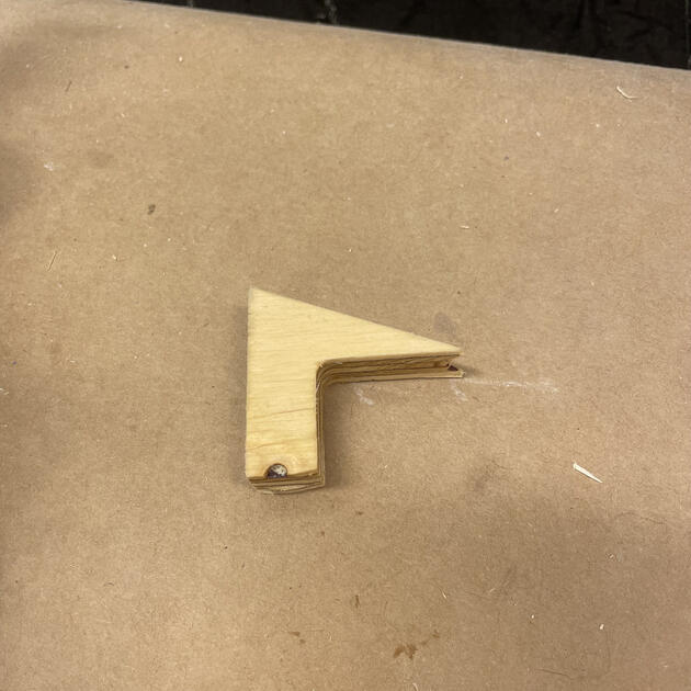
As shown on Figures bellow, the test cut turned out nicely, it snaps together ok (and looks like it would hold a bit of weight on it). Maybe I want it a bit more tight (I think I modified the design a fit after the test cut).
|
|
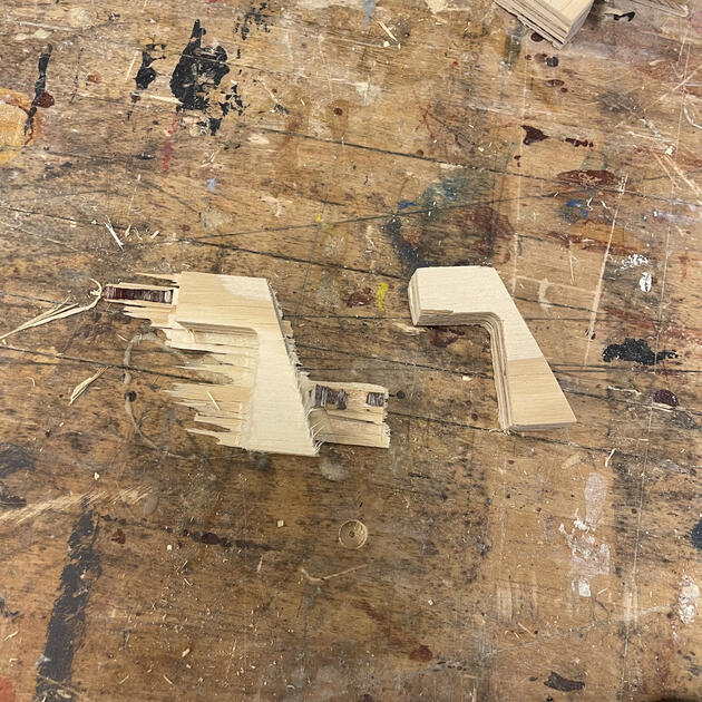
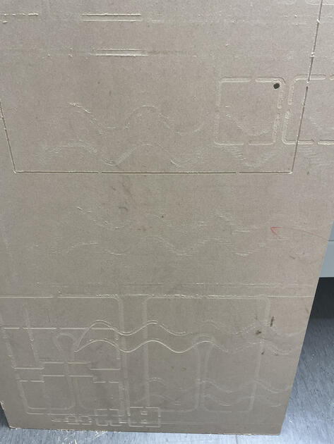
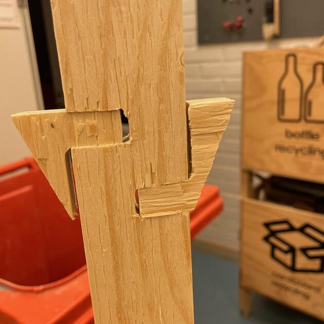
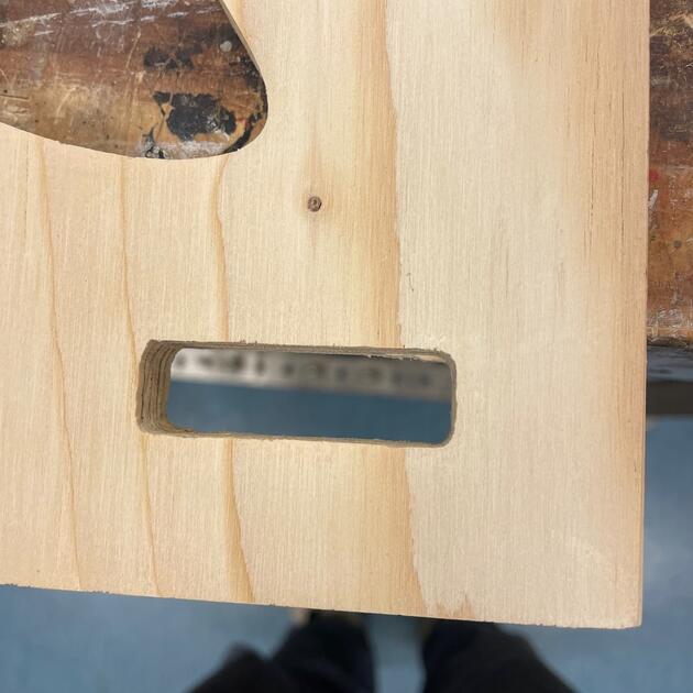
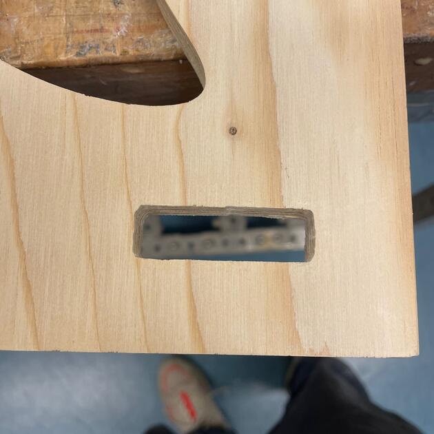
At this point I realized how difficult it is going to be to work with the wood we got. It was not too bad, but it splits easily, and I can’t apply too much force at it as it might snap altogether. The Figure bellow shows two test pieces, the left one is not post processed yet, just how I got it from the wood sheet, and the right one is already sanded.
4. Milling process
Since the test piece was success, I then prepared for “the big milling”. The whole process took several hours, since we had to prepare the machine and watch the cut the whole time. I am utterly grateful to Fiia for her patience in fixing the machine and explaining the things I didn’t understand.
CNC milling timelapse
CNC milling real time
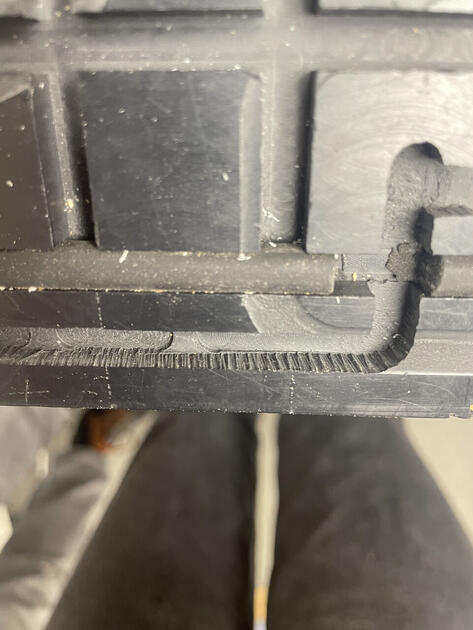
The big task was to make sure that the wooden sheet lays very flat on the CNC machine, so the cut is the same depth everywhere. I was trying to cut through the wood all the way through or leave a very thin layer at the bottom. The reason was that the wood splits fairly easily, and I didn’t want to damage it while getting it out of the wood sheet. But I also didn’t want to damage the sacrificial layer (Figure 25). I managed to not scratch it too much, and the final cut looks quite nice.
|
|
Cleaning the CNC
After we are done using the CNC room, we need to clean it and put all the tools, toolholders, clamps (…) back where they belong.

|

|
5. Post-processing the wood
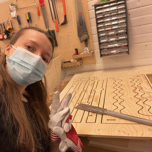
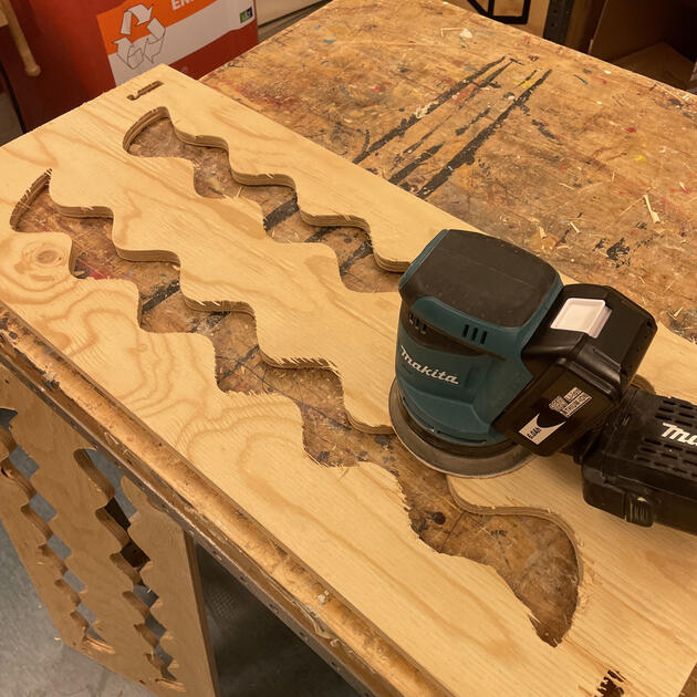
As always - safety first. I wore gloves for most of the time as well as face mask. Not sure how much is the face mask required, but I am quite sensitive to breathing some small particles, and it felt better having at least some protection against dust. During sanding, I also wore glasses and a helmet with the ear muffs.
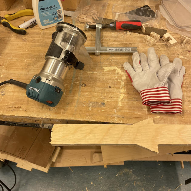
I first started by removing the tabs from the legs. I used the Makita tool that can be seen on Figure 30, because everyone was using it. However, I did not really like it because it just felt too powerful and somehow too dangerous fur such task.
Then I used the sanding paper and by hand sanded all the small joints, and more inaccessible parts of shelf legs.
Some time later, Solomon showed me the big sanding machine next door, which can also be used to remove tabs.
To use it, you have to be quite careful, and slowly approach the rotating sanding paper. You need to notice in which direction is the sanding surface moving and then expect a pulling in that direction. As long as you make sure that your wood piece is parallel with the sanding surface, it’s all good.
I liked that machine much more because it was quick and simple to use. I can also imagine sanding a round corners with it or something. Very nice!

|

|
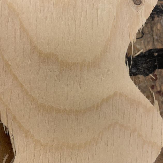
The next task was to sand the big surface of the shelf. For this I used the small Makita sanding machine.
On the two Figures bellow, you can notice the big difference on the rough side of the wood before and after sanding! However, I wonder if it’s only because the wood dust got into the small gaps in the wood which made it look smoother.

|
|
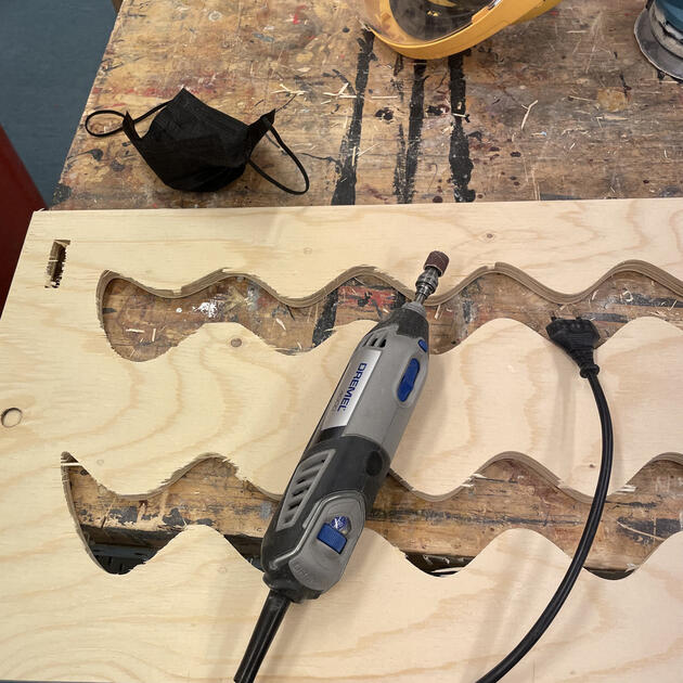
The last thing to do was to even and sand the inside parts of the shelf (the waves). For this I used the Dremel tool (apparently the most useful tool in the lab). The problem with it was that it was wobbling a lot, and it was getting out of the rubber holder. I managed to use it enough to sand all waves, but I was either using it wrong or the rubber holder is broken because it was quite an unpleasant experience - very annoying putting it back to the place every 10s.
6. Applying protective coat
We did all the sanding to make the surface smoother, not just for the good feeling, but also because then the protective layers hold better.
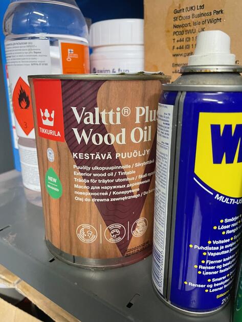
The big thing for me was the make to wood more durable, but now yellow. I really like the natural color of the wood (light beige). I noticed that some wood oils turn the wood we got to more yellow shade, like Arianas stand (Figure 38).
To put a protective layer on a wood (aka wood finish), one has few options:
- Varnish: Can be transparent or colored, made of oil and other stuff. Hard, durable protective finish. Good UV protection, dries slowly.
- Oil finish: Sort of like a wood treatment, it doesn’t only stay at the top, but seeps into the wood. Can improve the appearance of the unfinished wood, enhance the natural grain.
- Wax finish: Seems like it provides only short term protection? Multiple applications needed. Quite soft, can be formulated into different colors.
- Lacquer: Solvent-based finish, nourishes and improved the grains of the wood. Can be scratched. Quick drying, can be applied with spray. Glossy?
- Water based finish: They have less odor (smell) than oil-based finishes. Thin and dries easily.
- Other: There are other methods that can be used to finish / protect the wood such as french polish or shellac. I just touched the surface of what can be done, but this quite helped me in deciding what I want to apply on my wood.
Source of the information above.
We had 2 types of transparent wood finish in the lab - the wood oil, and oil wax. I knew that Ariana used the Wood oil, and it did color her stand quite a bit, so I didn’t want to use that.
|

|
I tried to do a test layer of the osmo oil wax on some small piece of the shelf. It didn’t look the best, and also Zhicheng told me that it has quite a strong smell, and he had to wait for a long time to get rid of it (perhaps it is meant for outside use only?).
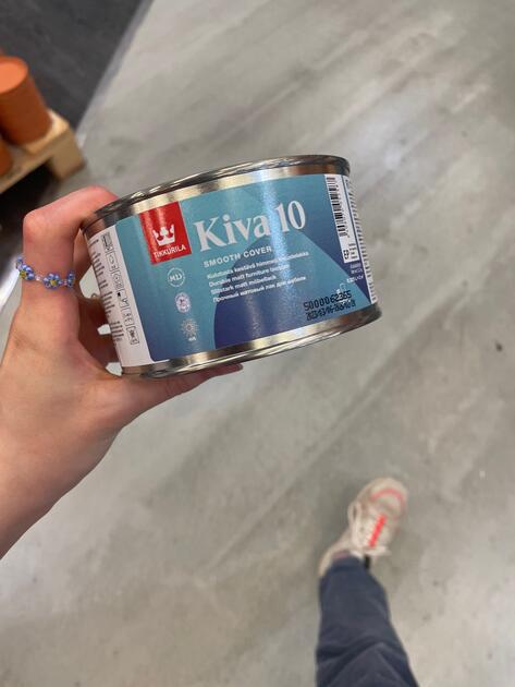
I went to K-Rauta and asked around. My goal was to find some wood finish that won’t make the shelf more yellow, and is safe for inside furniture. The very helpful lady there gave me two options, water based wood lacquer or a wood wax. She said that the wood wax could turn the wood a little yellow, but we could add a bit of color to it. However, I didn’t like that as I didn’t want to hide the natural look the wood, just protect it. So I decided to try the Kiva water based lacquer. It had even specifically stated on the cover that it is a “non-yellowing” wood finish. Perfect!
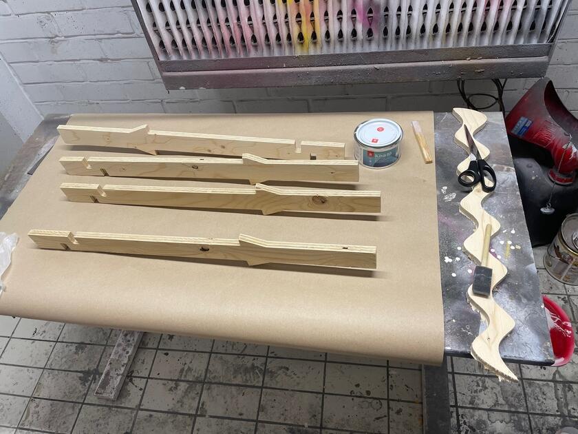
Spend a few hours to apply 1.5 layer of the wood lacquer (the legs and joints have two layers, but not the bigger pieces as I felt the lacquer made the wood a bit dry).
I was quite happy with the wood finish I chose. Not everything was perfect –> depending on how thick layer of lacquer I applied on the wood, it got a bit of different shade (Figure 45), but it is not too visible.
|

|
7. Assembling
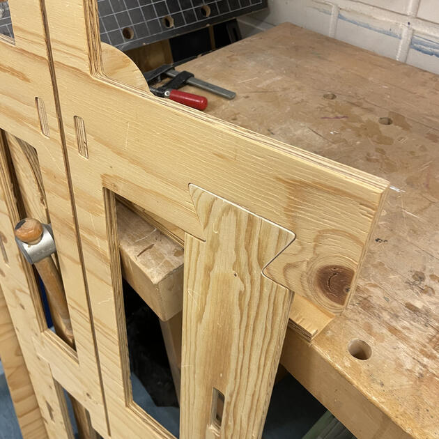
The last thing to do was to assemble everything together. I made the joints and the holes for legs quite tight, so the shelf won’t wobble. I still think it was for the best (since I didn’t have to use any sort of glue or anything, and it holds nicely together), but it also meant that some joints won’t fit perfectly. Normally, I would just push them there, or file them / the hole a bit, but the problem was that the wood was so easily split that I didn’t want to risk breaking it.
|
|
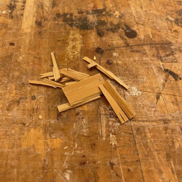
Even when I tried to be gentle (but firm), I broke off some smaller pieces from the main wood.
The legs didn’t completely fit smoothly to the holes made for them (perhaps because of tabs?), so I had to file them a bit.
|
|
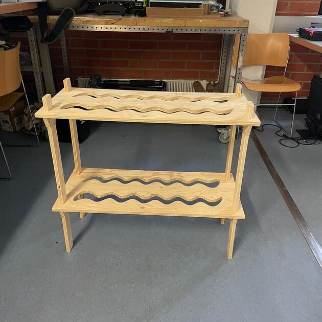
And this is how the finished shelf looks! I really like it :)
The whole process took some time, but would definitely do it again. I really like how much can be done just with the sheet of wood and the machines we have at lab. Hopefully the shelf will be durable.
8. Files
Shelf dimenstion .dxf - [Download]
Shelf Fusion 360 file .f3d - [Download]