Week 12: Molding and Casting
Group Assignment
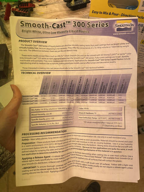
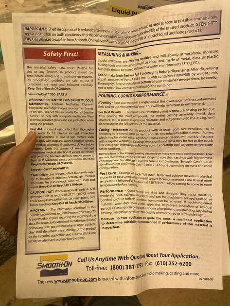
The page describing the group assignment for this week (review the safety datasheets, make and compare test casts, compare printing vs machining molds) can be found here.
Introduction
This week we looked at molding (process of creating a hollow cavity that replicates the shape of an object or pattern) and casting (process of pouring a liquid or molten material into a mold cavity to create a solid object with the desired shape). The goal is to make a design, then mill the positive mold out of wax, following a negative mold from silicone and finally cast the desired design from liquid plastic.
I was doing this week a bit later than the rest of class, and it had the reputation as one of the hardest weeks. However (perhaps because I was prepared for the worst), it turned out to be really fun and interesting topic!
Design
Original idea was to make a cup coaster (because I need some, and with casting it is easy to make multiple ones fast), but they were too big for the wax cube we had at the lab. I had to improvise fast, and the second-best thing I came up with were fat crocodiles.
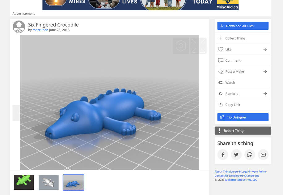
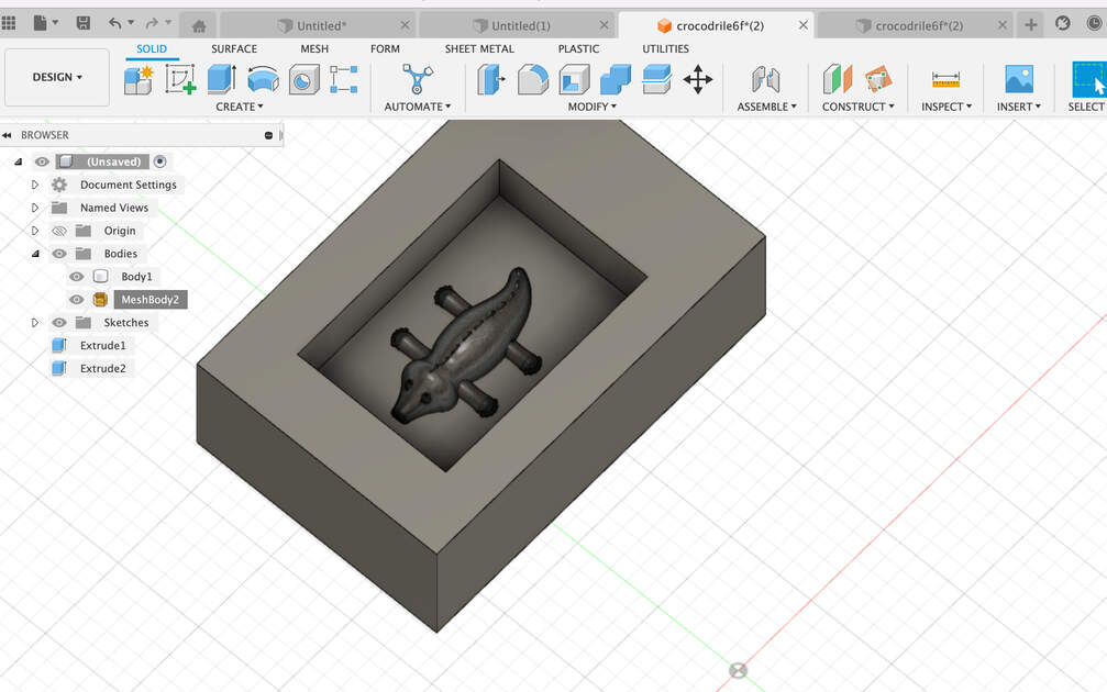
After quick scrolling through Thingiverse, I found a suitable model. Yay! In Fusion 360 I made a proper positive mold - I didn’t do any complicated steps, just added a box of a size of wax cube we got, with a hole for the crocodile. Joined them by aligning point to point the bottom of the mold hole and bottom of the crocodile. You can find the Fusion360 files at the bottom of this page.
Now that I have a design of positive mold, it was time to mill it. We have a Roland MDX-40 which is smaller than the CNC we used for the week 7, but bigger than the PCB milling machine. It can be used for both PCB milling and “carving”, limited only by its size.
The plan is to first make the mold from foam (soft material) so I’ll learn how to use the machine with some safe, quick to mill material, and them I’ll carve it into the wax. I will make the toolpaths using the VCarve -> same software as in the CNC week.
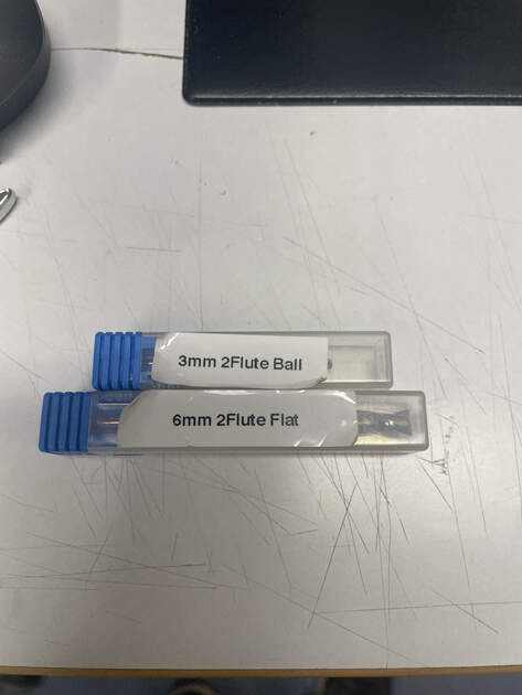
I used 3 different tools: a butterfly end mill (used to level the surface of a material), 6 mm and then 3 mm tool. We use first the bigger, then the smaller tool because it is faster to mill the material with bigger tool, but them we can achieve finer details with smaller tools.
Pro tip: Make the walls bit at the angle (like this \___/ ), so the tool is not hitting them every time it is around. The tool is cylindrical (thinner at the bottom, where it is milling). When the walls are straight, the wider part of cylindrical tooltip can hit the walls -> there can be some friction, it can even melt the wax.
VCarve - Toolpaths and Calculations
In this section I’ll explain how I used VCarve to made toolpaths. There are many settings, so I’ll just describe the ones I used. The proper explanation by Kris is here, and some other helpful video is here.
I have to admit that after the CNC week I was not looking to work with VCarve again - the software confused me and I felt that there are too many setting that can co wrong. But this time s I was not in a hurry, and I could use the MDX-40 even without supervision. I took my time, watched few videos, then did the calculations, and overall did multiple different toolpaths with VCarve (alone). And it worked nicely, and now I no longer feel anxious to use that software.
My setup:
1.Create a new file
Job setup:
2. Select single sided job for what we want to carve (other options are double-sided and rotary)
3. Specify the job size, which is the size of the (foam or wax) block
4. Z zero -> we used the material surface, that is also where you will then put the bed leveling tool. We could also put the material surface and then put the bed leveling tool on the machine bed surface.
5. XY datum position on southwest corner
6. All done for job setup! Hit OK
The next step is to draw rectangle? Not sure why this step is needed, perhaps just to select the whole area. We don’t create it, just close the pop-up then.
Import 3D model
File -> Import -> 3D model (should be .stl)
We don’t have to do this step if we are only leveling the top surface (for example if the foam is uneven).
There will be Orientation 3D model menu - I like to use Center Model for Model Size, and for Zero Plane Position in Model the simplest thing is to have zero depth bellow the top (e.g. the whole model “counts”).
Toolpaths:
7. Do the Material Setup
8(a) If we want to level the material surface, we can use the pocket toolpath, and then cutting depth of 10 mm for cutting of the irregularities from the top of the foam -> for this the start depth should be at the surface of the material (0.0), and the cut depth how much we want to cut off, in our case around 1 cm. The tool is then 22 mm end mill (butterfly end mill), then enter the proper stepover.
8.(b) For 6 mm tool we used the roughing toolpaths. This is smaller tool, so it can make some lever of detail, however not that much. We are doing this step because it would take forever (circa twice as long?) to mill that much with the 3 mm tool. In the menu specify some machining allowance (it will leave some extra material on top of the model, so we can mill it off later with the finer tool), for example 0.
8.(c) For the 3 mm tool pick the finishing toolpath. Specify a finer stepover.
10. Pocket allowance set to negative half tool size
Pro tip: Limit the model boundaries, so it’s cutting in the pocket only.
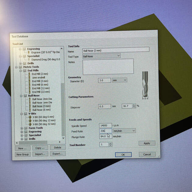
Tool calculations:
- Spindle speed (r.p.m.) - the machine we have at the lab can go (from 4500) up until 15 000, but for safety and other reasons we usually put only 14 000 there
- Feed Rate (mm/min) - depends on the chip load (diameter of tool and material we want to cut dependent), number of flutes (tool dependent) and spindle speed (machine dependent)
- Plunge Rate (mm/min) - feed rate divided by 4
We get the chip load from the table of the tools we have at the lab (Sorotec) (Figure bellow).
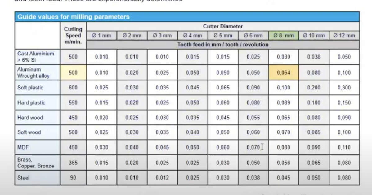
The formula to calculate the feed rate is:
Feed rate = chip load * spindle speed * number of flutes
After we calculate the feed rate, check if it within the machine limits (should be stated somewhere close to the spindle speed data).
Now name the toolpath, and you hit calculate. We can see a nice animation :) (it’s nice, but when I had more complicated design, sometimes it crashed the VCarve)
Save the toolpaths
11. Be sure to choose the right machine.
Roland VPanel Software
Looks and works very similar to the smaller PCB milling machine. Make sure that in set up the NC code is selected, and we are working with G54 coordinates. Position your material (we taped it down with double-sided tape), “manually” set the origin for X and Y axis. I personally like to use sensor to set Z origin, but you can also do it manually as well (can even achieve more accurate depth when the PCB milling).
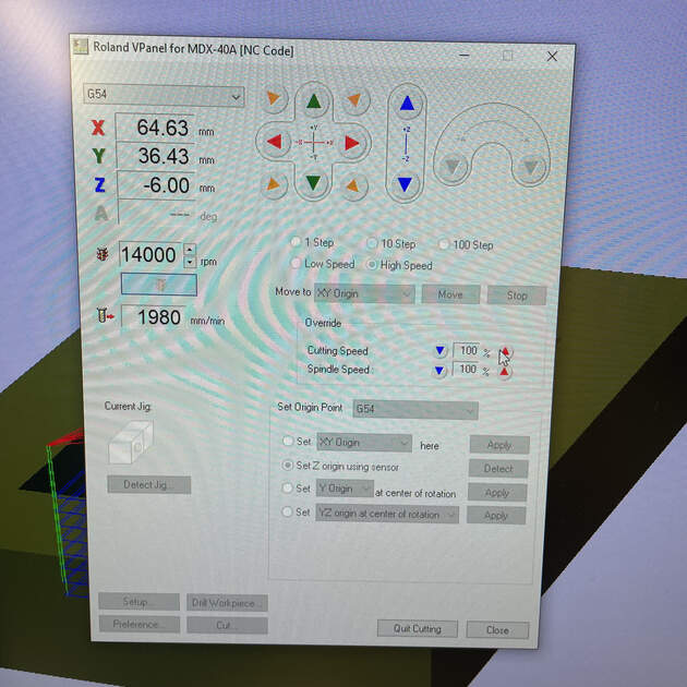
IMPORTANT! Before you start to cut, reduce the cutting speed to 50% for foam (for cutting wax, to 10%), and make sure the spindle speed is set to 100%. We do this to make sure the machine can handle the feed rate. We can then increase the cutting speed if everything goes well.
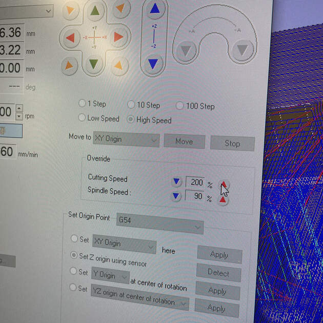
Now you can select Cut, delete all previous jobs, add your file (job), hit Output. Cutting will start!
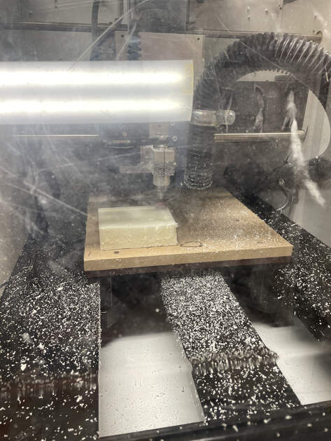
Foam - preparing and milling
First, I cut the foam to get a block of similar size as the wax one we got.

|

|
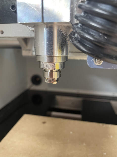
Then is time to prepare the machine. I have to add a collet there with the hole diameter matching the tool I would like to use. In case of butterfly end mill it is 6 mm.
We screw in the collet, then insert the tool into it, and then tighten is with two wrenches, so the tool holds there. It is important to tight it properly, but not too much!

The MDX-40 machine had (similarly to the big CNC) a sensor for setting a Z-axis origin.
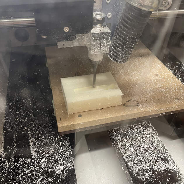
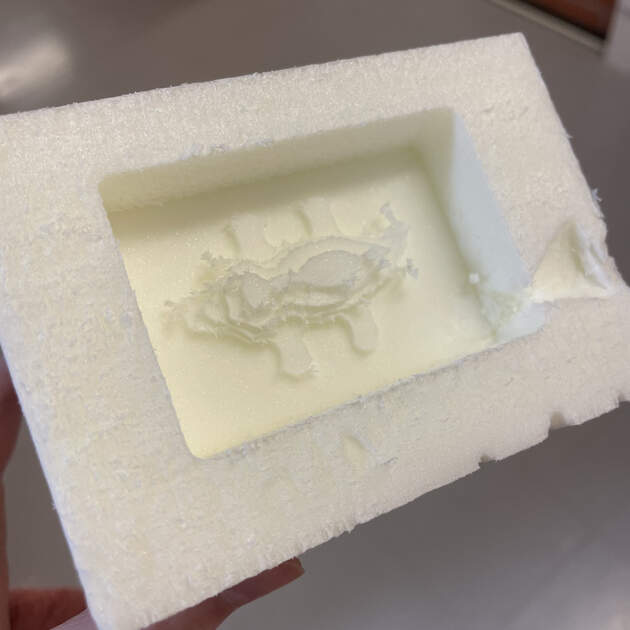
The milling process doesn’t take that much time when using a soft material such as foam. Everything worked smoothly for me. I haven’t used a 3 mm tool for the foam because it was just a test mill and the proper one was the wax one.
|
|
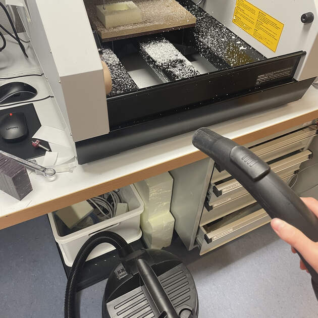
After we are done with milling, it is important to clean after yourself. That includes removing the material, vacuuming the foam particles from front, moving the bed (can use the view feature on the MDX-40), vacuuming the back and removing the collet.
Troubleshooting
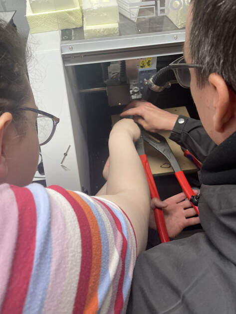
When I wanted to start doing the wax milling next morning, I found a collet used for PCB milling stuck in the machine. I couldn’t get it out. I think the biggest problem is that people get confused which direction is tying and then use too much force and make it stuck. Maybe we should add a sticker / a diagram / a picture to prevent this issue in the future?
When pushing wrenches away from each other, we are releasing the tool.
When pushing wrenches closer together, we are tightening the tool.
Kris to the rescue! Bus seriously, it was pretty cool how much brute force was needed to remove one collet. At the end we broke it and had to order a new one.
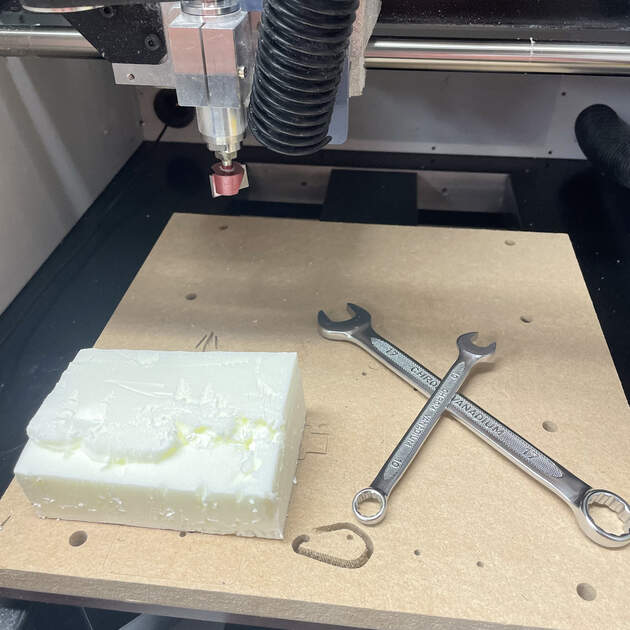
Wax - preparing and milling
As the foam milling went well, we could continue to do the wax milling. First we prepared the machine, e.g. sticking the wax cube to the bed with some double-sided tape, changing the collet and inserting & tithing the tool.
We then set the origin of X, Y and Z axis.
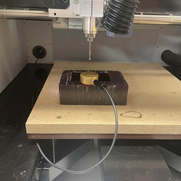
The real time wax milling
Timelaps of the wax milling
This part took quite a some time. The milling process was slow, and I had to watch the machine at all time while it was milling. Reserve at least a half day for this.

|

|
At the end the wax mill looked okey. I think next time I wouldn’t use the “Offset” for area machine strategy. But rather first horizontal “Raster” and then vertical “Raster”. I heard that this way I can achieve a way nicer finish than what I got.
Pro tip: I never milled wax before, and I was not sure if the CNC sounds “ok” or if something is wrong. So it recorded the CNC sound for reference! (everything was ok)
Silicone casting
The next step is to make a silicone (negative) mold. This was done in the Plaster Room.
We had to do numerous precautions as we were working with toxic chemicals that might cause allergic reaction, and a long exposure to them is not good. We had to wear a special vinyl gloves that wouldn’t react with the mixtures, and ideally also a protective glasses.
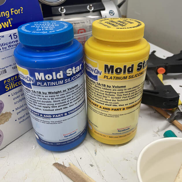
Read the instruction before you start. The main thing was that the mixtures needed to be properly stirred (which was hard because they were quite viscose), and then mixed in 1:1 volume (or weight) ratio. We used scale to measure the weights of substances A and B. After we mix them together, we have about 45 min before they start to cure.

|

|
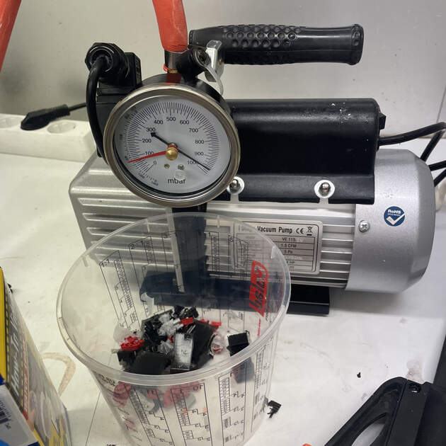
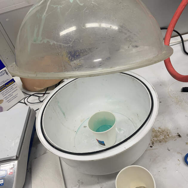
After stirring the mixtures together, there was a lot of air stuck in it as the liquid was very viscose. When the mold cures, and these bubbles are on the bottom, it could disrupt the surface. So we want to get rid of these bubble, and the way we do it is using the vacuum chamber. Multiple times (until there are no bubbles on the surface of the mixture) we decrease the pressure (as is we are trying to create a vacuum), and then slowly increase in back to the room pressure.
|
|
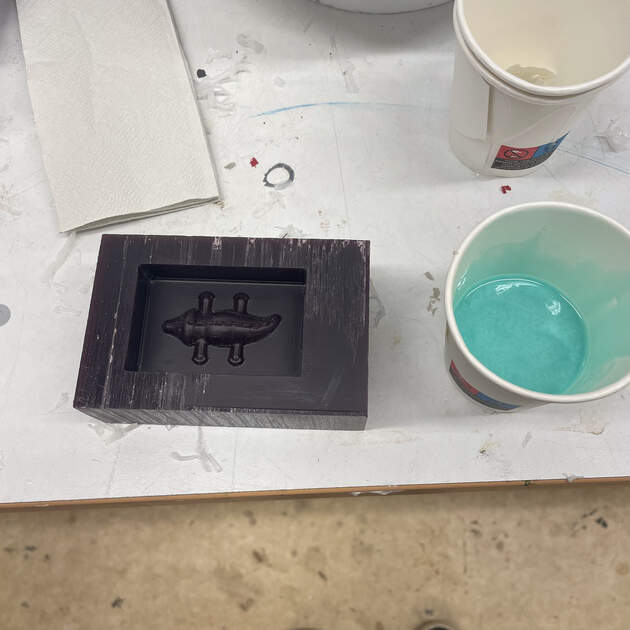
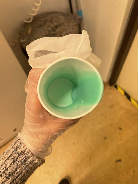
Now the mixture is ready to be poured. We try to pour is in a thin stream to the lowest place out the positive mold.
|

|
I think I managed to not be wasteful by measuring (in grams) how much water fits into the wax cube, and then making the mixture slightly heavier than that.
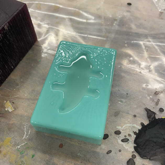
I was really excited for the silicone mold to be done. It was supposed to be cured in 4 hours, so I waited 4.5 hours to take it out and surprise, surprise, it was not. It felt like it was almost done, bit squishy on the surface, and a thin layer of it stayed at the bottom of the wax cube.
|
|
However!! I took this as an opportunity to make the crocodile smoother (it had some lines from the imperfect wax milling), and made some features (his toes) more significant.
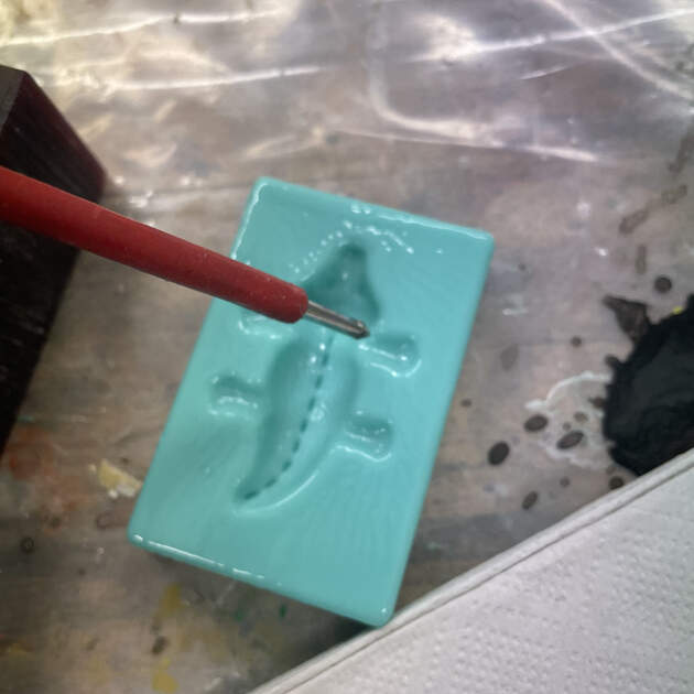
Pro tip: You can paint the silicon mold with silicon to reduce the impurities (for example the lines from 3D printing).
Liquid plastic casting
The last thing to do was liquid plastic casting. It works very similarly as the silicone casting.
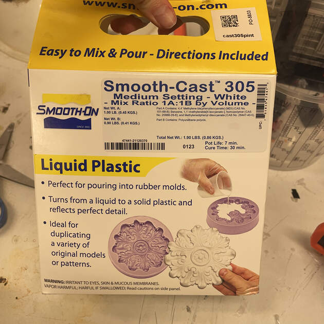
As before, it is necessary to read the instructions. This time the pot life (how much time we have before the mixture starts to cure) is 7 minutes, and it will be cured in 30 minutes. So we have to work quickly! The mixture is not that viscose (feels like normal water) so we don’t have to “debubble” it in vacuum chamber. The mixing ratio is 1A:1B by volume, but I think that the substance B is slightly heavier, so for 100% of mixture A, we will add 90% of mixture B.
|
|
Pouring worked similarly, where we wanted to pour in a thin stream to the lowest point. After that was done all there was left to do was wait.
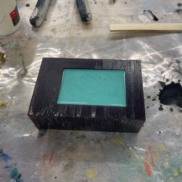
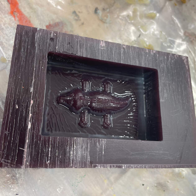
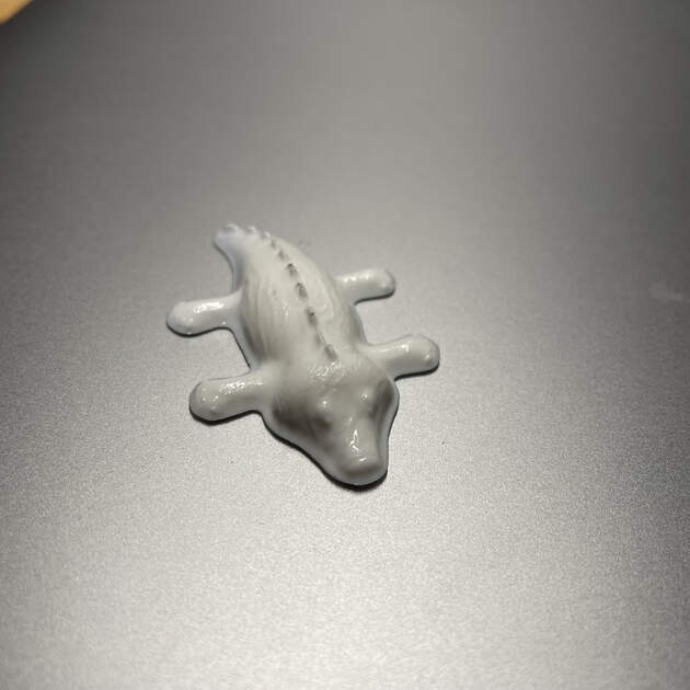
And it’s done! My own little fat crocodile. It looked good, but I think I put too much of the liquid plastic there, so it’s extra fat.

|
|
EXTRA 1 : Experimenting with colours
I wanted to make the crocodile green (as crocodiles are supposed to be!). We have some coloring at lab, so I read the instructions -> it only said that they are super toxic, and you just add a bit of it to the mixture before it cures.
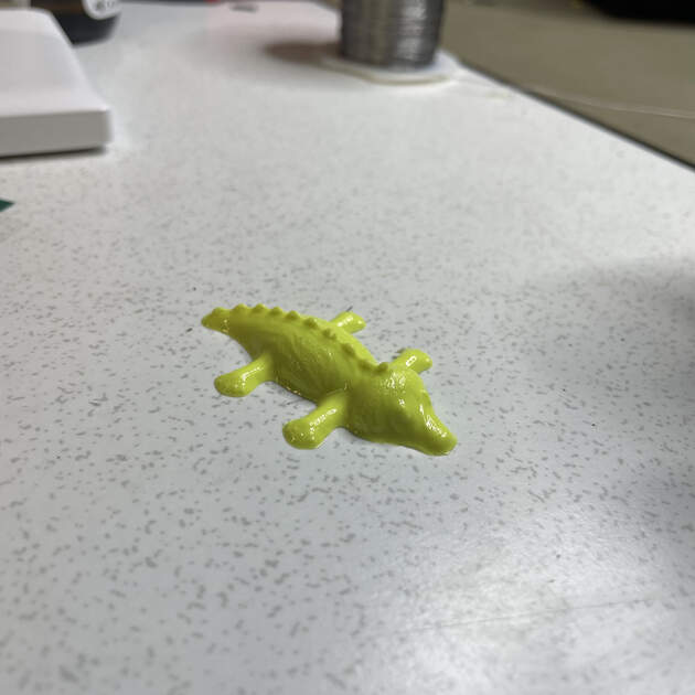
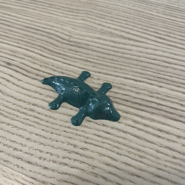
I tried adding the green one, but the crocodile turned yellow. So I added more green, and the next crocodile just turned more yellow… One can obtain green from mixing blue and yellow, so I tried to add a little bit of blue to the next mixture. This finally worked, and I got a dark green crocodile.
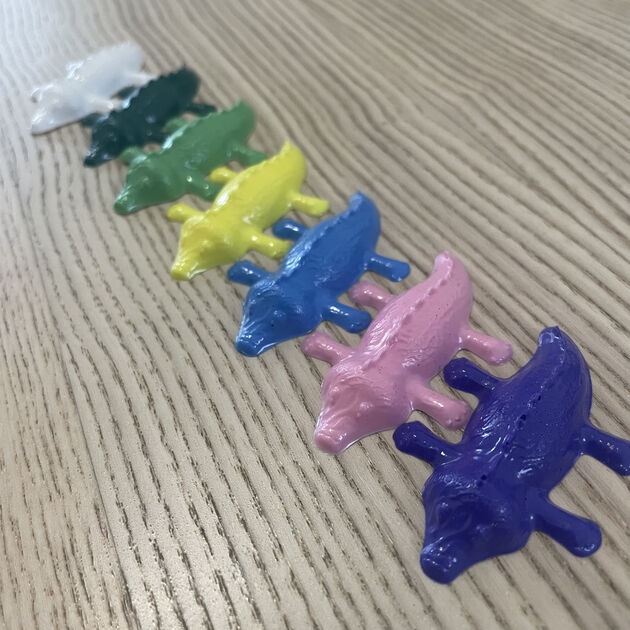
I then experimented a bit more, tried to make more shades of green and different colors. It was nice and fun! (for example when you use red, the crocodile turns pink. I assume it’s because the liquid plastic is by default while). Now I have a small fat crocodile army.
EXTRA 2 : Making a food safe mold
At this point I was obsessed with my crocodiles, and I wanted to make them from chocolate as well. But it is not that simple to make the food safe chocolate mold.
For this, I didn’t do the positive mold out of wax as before, mainly because it takes so much time. I wanted to 3D print it! PLA is not food save, but we had a PETG at lab, which is. I was worried whether it is ok to print it using the same 3D printers that used PLA before, but apparently it’s fine - PETG uses higher temperature compared to PLA.
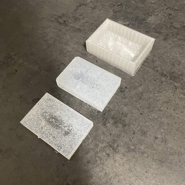
I then used the SORTA-Clear food safe rubber to make the negative mold.

|
|
The silicone was super viscose, and even with the vacuum chamber it was super difficult to get rid of the bubbles. So the mold turned out to be very bubbly.
Now to the fun part!! Making choco croco.
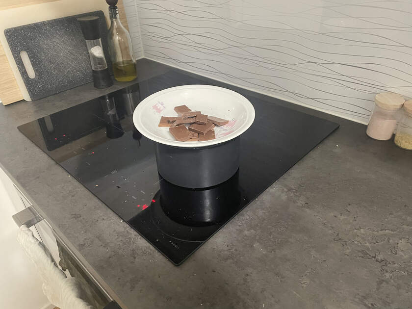
First melt some chocolate in the water bath:
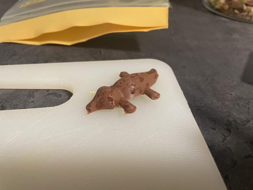
Pour the melted chocolate in the silicone mold, and here it is, out first (not really successful) crocodile!
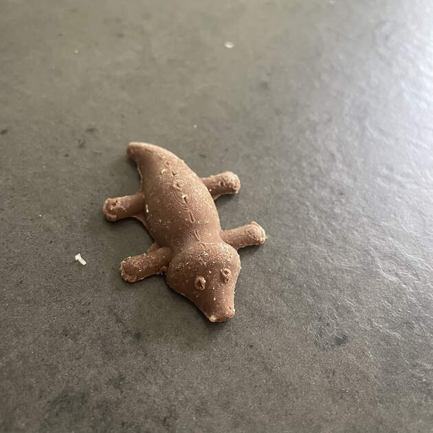
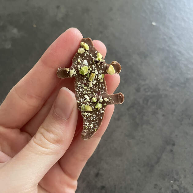
I also added some crushed pistachios on the bottom, to make it more green (and tasty). Overall I made about 25 of them. It was a lot of work as I only had 2 silicone molds, and the chocolate needed some time to solidify (I was putting it in the freezer to make it solid quicker). But at the end, they were very yummy.
|
|
You can notice faint lines on the crocodile - layers of the 3D print from the positive PETG mold.
Files
Fusion 360 model of the mold - [Download]