Week 2: Computer-Aided Design
This week we started to look at 2D and 3D modelling. The aim was to try different modelling tools such as Fusion360 or FreeCAD.
It was interesting to hear that we should try to have the sketches fully constrained at the end of sketching/modelling. I was aware of the parametrisation feature in Fusion and used it a lot, but never noticed the degrees of freedom.
OpenSCAD
When I first heard about this software, I was intrigued because you use programming to model something in 3D. There is no need to have sketches since you can directly model the 3D object.
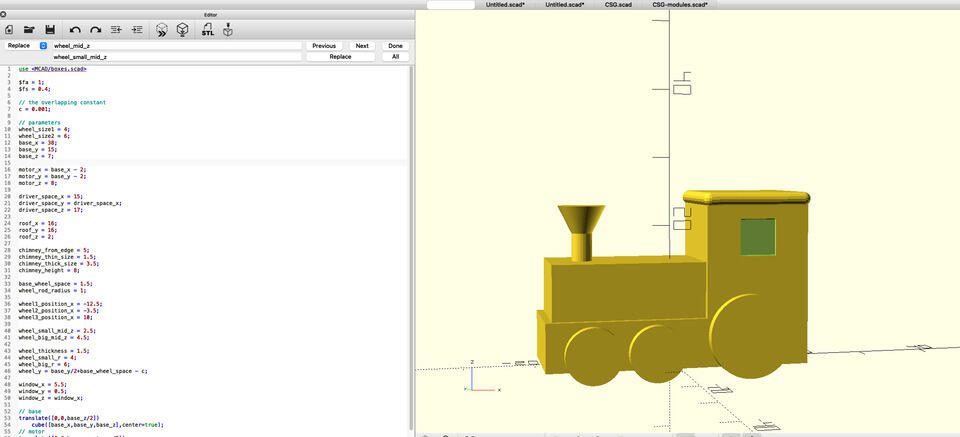
This is how the OpenSCAD looks like when you open the new project:
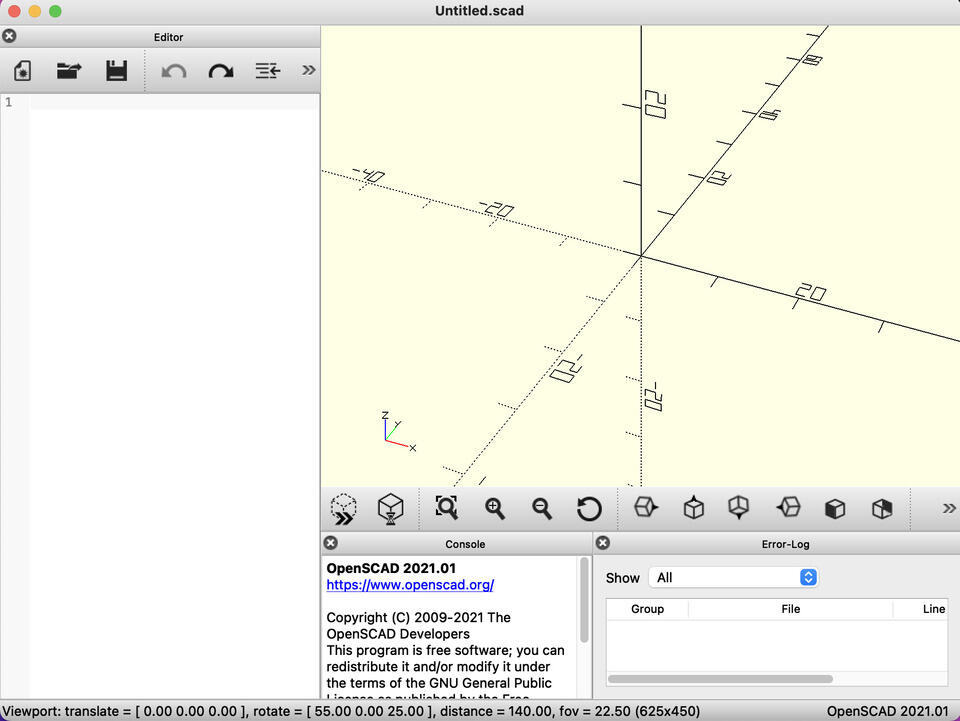
I did some tutorials and made some stuff, but I’m not an expert. Everything I’ll write here is just my findings and perceptions. When I started using OpenSCAD, the most important commands were cube, translate and rotate. Cube (or cylinder, or something else that creates shape for you) will create the object on your current position, translate moves your position on the plane, and rotate will rotate the object you are about to create.
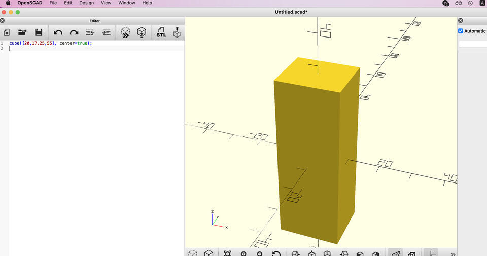
x = 2;
y = 4;
z = 8;
translate([x,y,z])
    rotate([90,0,0])
        cylinder(h=5,r=3,center=true);
The code above would be a valid code that would make something in the OpenSCAD. The first three rows define x, y and z variables. Then there is translate command, that moves the position on the plane where the object will appear. Next command, nested in this translate command (to indicate that this happens after it), is rotate which rotates the object 90 degrees along the x-axis. The last command creates a cylinder with radius 3 and height 5.
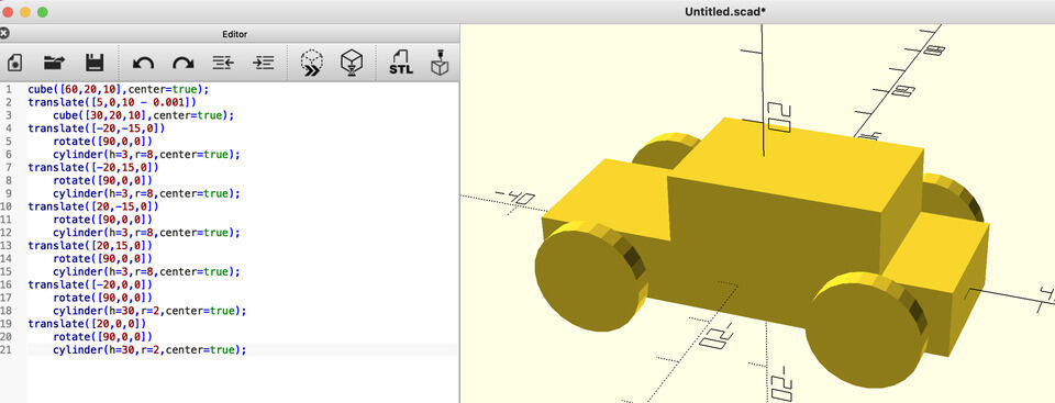
Using these simple commands I followed a OpenSCAD tutorial and modelled a simple car.
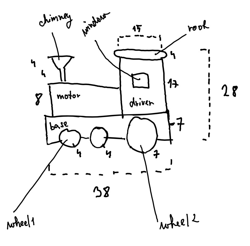
After doing this tutorial, I wanted a bit of challenge, so I decide to do my own model of train. First I did some brainstorming on how this train should look like:
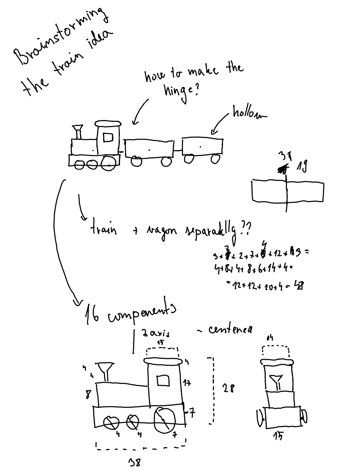
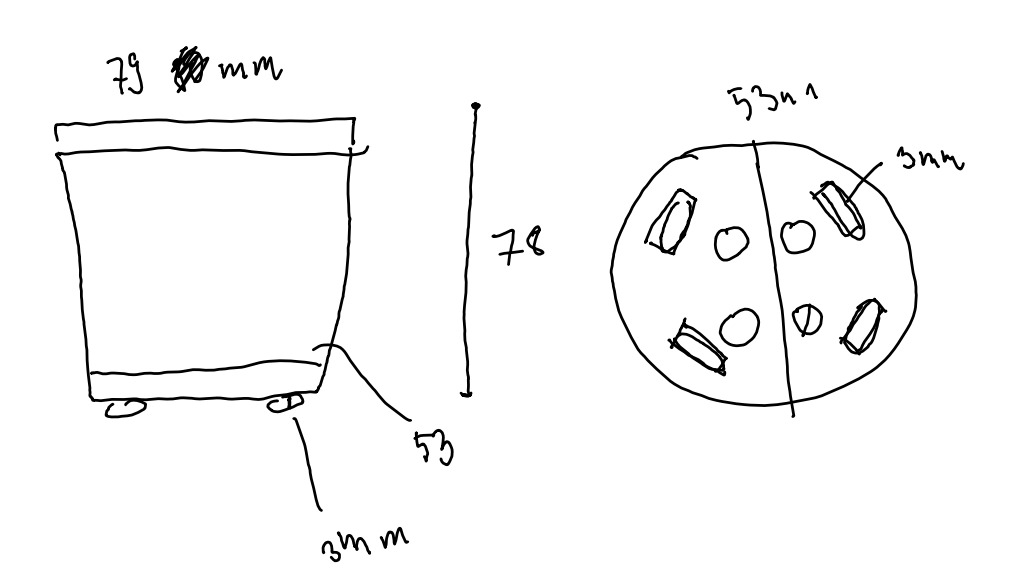
And one with dimensions:
The commands I used to make the train were the same as above, plus two extra concepts:
Combining objects - you sometimes want more complex objects, and you can often achieve that using boolean operations - union, difference and intersection.
union() {
    sphere(r=10);
    translate([12,0,0])
        sphere(r=10);
}
Importing external models - you can import models from the MCAD library, which is a library of components commonly used in mechanical designs. I used a round box model from it, which looks like and behaves similar to the cube, but has an option for rounding the edges.
use <MCAD/boxes.scad>
roundedBox(size=[15,5,30],radius=1,sidesonly=false);
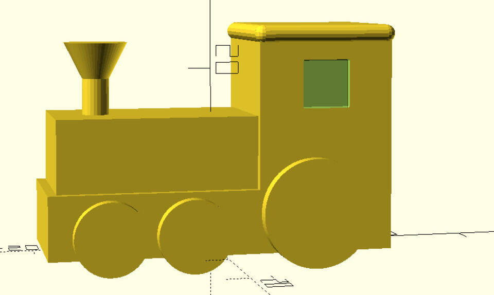
As seen on the figure above, I heavily parametrised the whole code, so all the train dimension could be easily changed (took a long time though).
One thing that I struggled to figure out was that when there is a nested translation (like translate, union, cube, translation, cube) then the second translation is not from [0, 0, 0] but from where the first translation “ended”. It now makes sense when I’m thinking about it, but before I just somehow assumed that the translation is always from [0, 0, 0] just because that’s how it is if there are not nested.
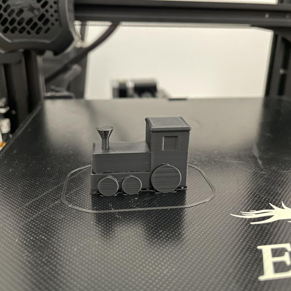
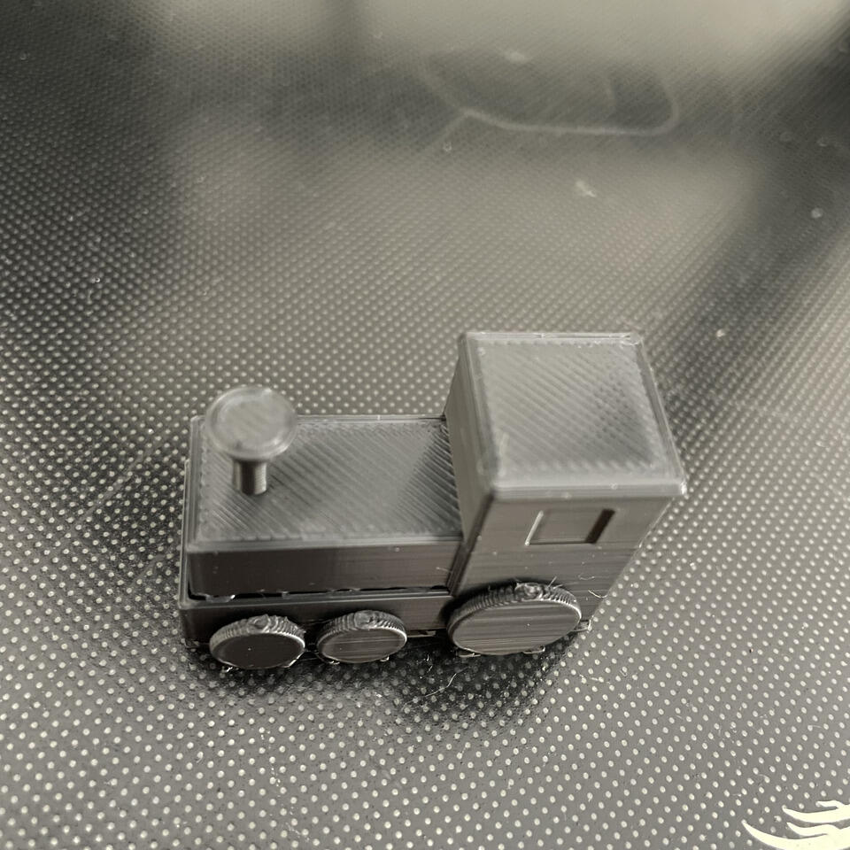
Now the modelling part is done. I rendered, sliced and printed my train, and it turned out really nice. I was proud and happy to print something that I modelled.
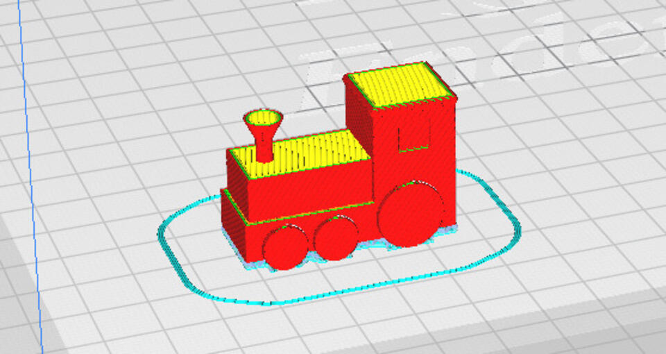
The print looks nice, but there could be some adjustments. For example, I haven’t realised that because the wheels are connected to the main body of the train with tiny rods, it was difficult to get them of the printer bed in one piece. (I broke one of the bigger wheels in half when I squeezed it to get the train from the printer). The other thing that could be improved is that you can see the infill between lower part of the train body and the upper part of the train body (Figure 9). Perhaps I haven’t overlapped those two cubes enough in the OpenSCAD?
|
|
Overall I would say that in some cases, this is the perfect software to use. When I want to make something where the same part is used multiple times (module), or where some steps are repeated (using loops), this would be my software of choice. However, the coding takes time. If I want to make a simple train as the one above, I would probably make it in the Fusion 360 as that would probably take less time. On the other side, the software is also not robust (can’t handle very complicated design made out of thousands of lines of code), and therefore maybe can’t be used in industry.
SolveSpace
SolveSpage is a software that was introduced during the lecture. I haven’t used it before, but I wanted to try to use it.
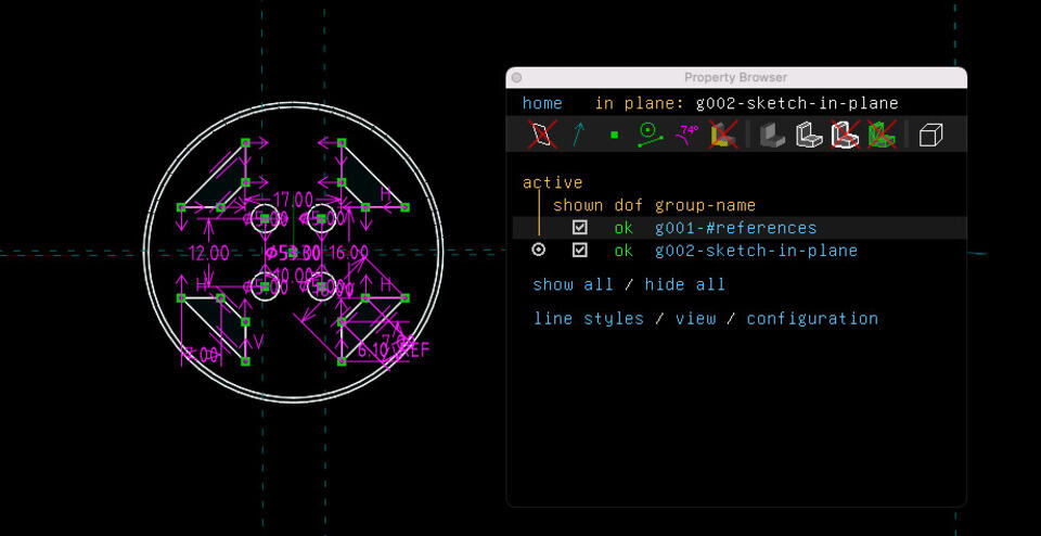
I really like how the “degrees of freedom” was visible during the sketch phase - it makes me want to have the little green “OK” there :)
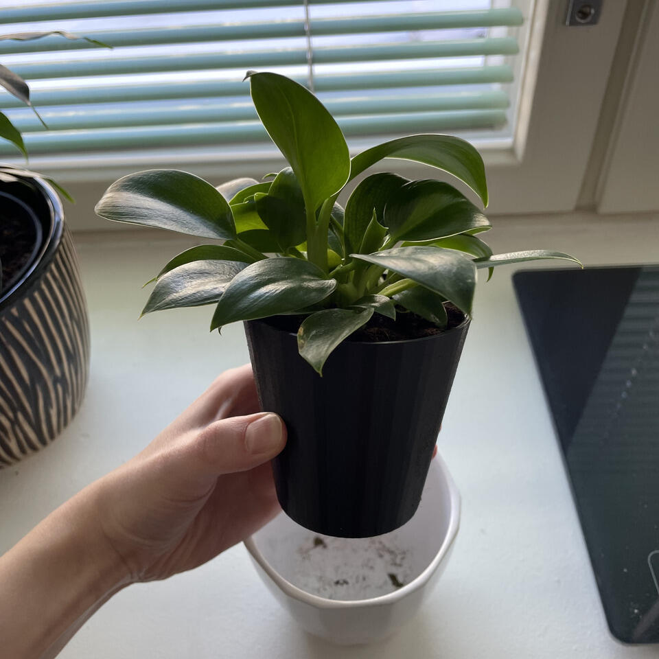
Regarding my model: there was a plant at home that would benefit from a bigger pot, so I decided to make one - it seems simple enough, but also a bit more complicated than just some boxes, so I can get to try more features of SolveSpace.
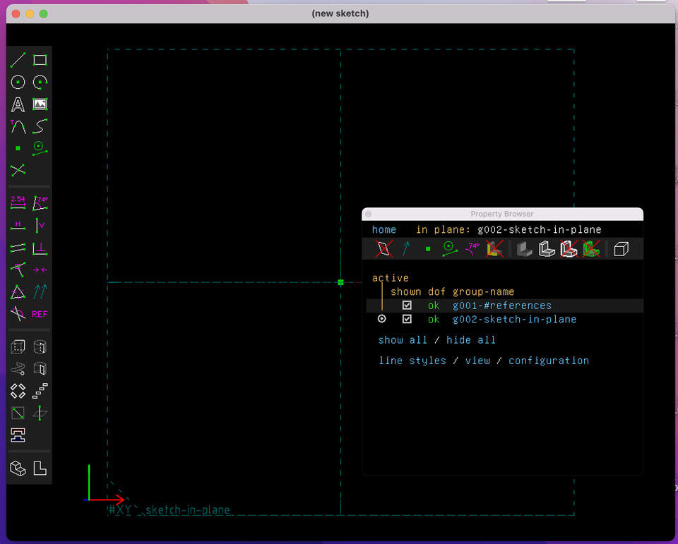
This is how the SolveSpace looks like when you open a new project:
At first (coming from a Fusion360 background) I made a really nice and detailed sketch where I wanted to extrude only some part of it. However, it turns out that this is not possible and probably also a bad practice in SolveSpace. I was a bit frustrated and didn’t understand how it works, and was looking for a hacks how to extrude specific surface.
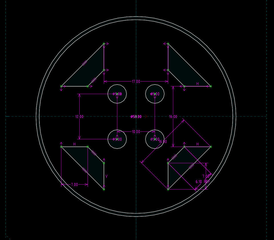
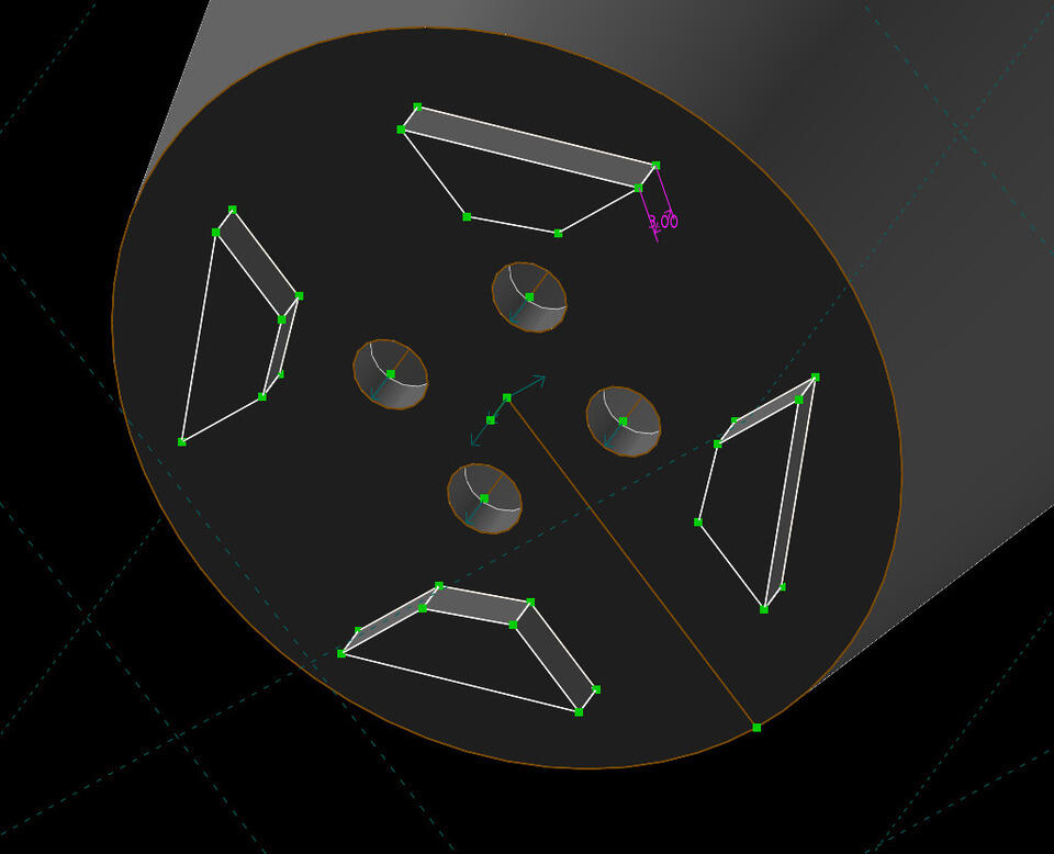
However, what I needed was to change my perspective. SolveSpace is not Fusion 360, and it works differently. After I adjusted to it, and understood that I need to sketch what I want to be extruded (at that time, then sketch something again), the whole process started to make sense and I progressed quickly.
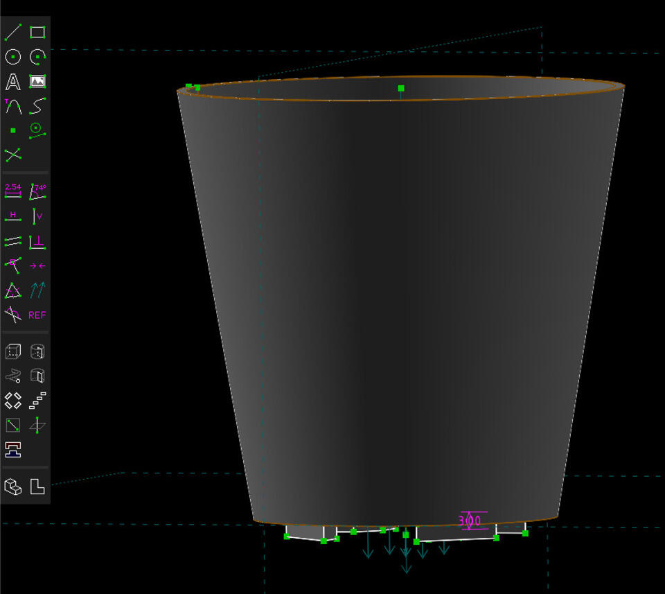
I made the cylindrical shape by revolving the sketch around the z-axis. Then the new sketch plane was selected using a point on that plane and selected the “New group in new workplane” button.
|
|
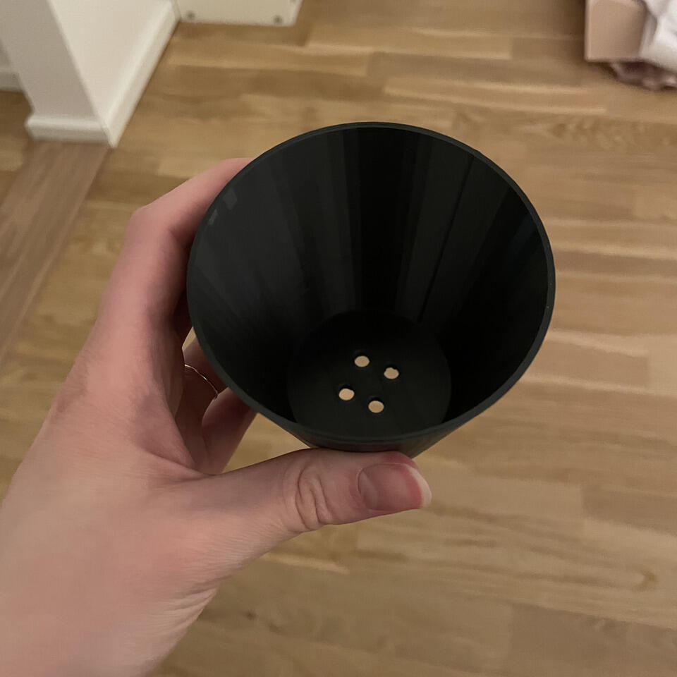
The final product turned quite nicely. It took around 4.5 hours to print, but that’s because the sides of the pot were quite thick - four full rotation per one layer. If I were to print another pot, I would make it a bit thinner, which would then take less time to print.
|

|
|

|
|
From my perspective, the advantage of SolveSpace is that it is perhaps less complicated than Fusion 360, and I found the interface more intuitive. The negative side is that SolveSpace is of course less powerful, and also I am still not totally sold on how the sketching and extruding works.
2D Raster Software - Krita
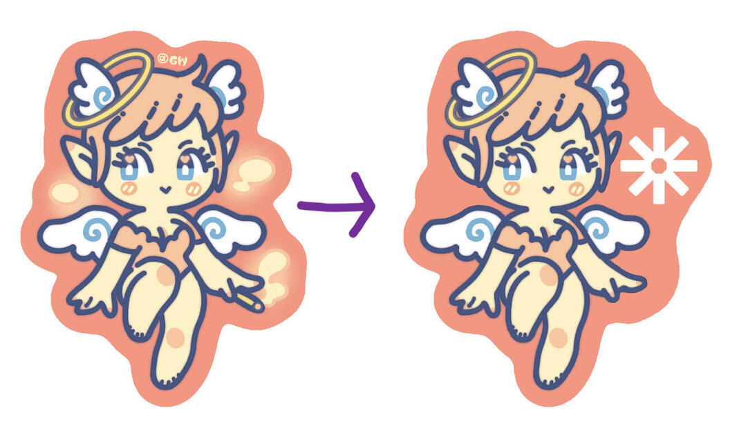
I explored the Krita raster software. I had a .png that I wanted to edit so it would not include a cigarette and it would include a logo of an organization I am part of. This organisation wanted to make patches, and bought the design from an artist called Grace Witherell. You can buy the original stickers on her Etsy here.
At the beginning I had some trouble figuring out the shortcuts (for example the zoom is control and “+”, changing the pen size is shift and mouse scroll to left and right), but then I was surprised how easy it was to make the changes fast.
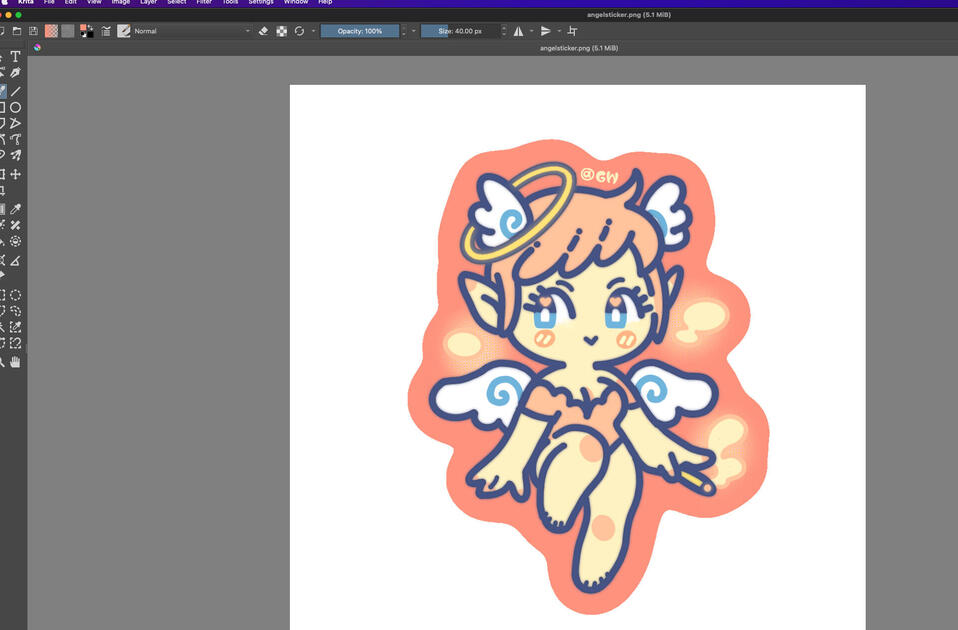
As this was a raster software, you could see the individual pixels when you zoomed in.

I used a pen to pick up the original color, and then draw over the parts I wanted to hide. I also imported ESN logo, and included a text with current year. We then sent this design to a patch making house company.
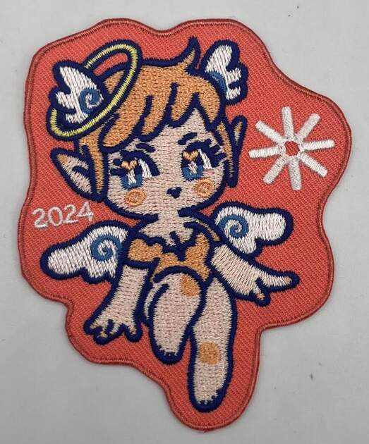
I will not include a high quality files here, as they belong to the original artist.
2D Vector software - Cuttle
I went on a holiday to Lisbon, and I really like the stained-glass windows they had. The colors were beautiful, and it made the whole space to have a different feel.
I wanted to make my own little sun catcher, perhaps out of colored seethrough vinyl, which I can then cut on the vinylcutter. Then during the nice sunny days (rare in Helsinki), I can be reminded of my time in Lisbon.
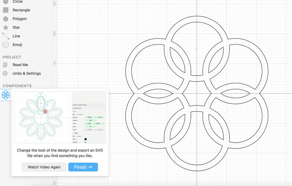
I will design this sun catcher in Cuttle software. I first used the very nice tutorial they had, where I got familiar with the commands and capabilities of the software.
Then I got to design the sun catcher! I first did a little sketch how I want it to look like.
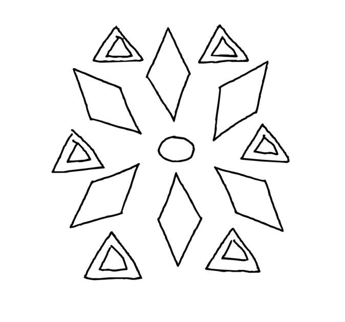
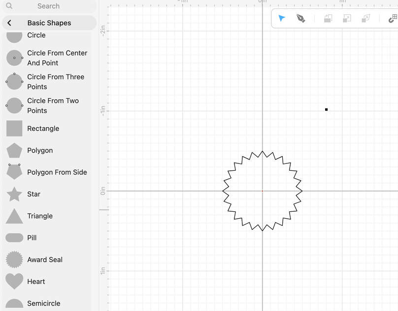
Then I however found the advanced shapes option. I really liked the star shape, it reminded me of a little sun, so I used that as a middle.
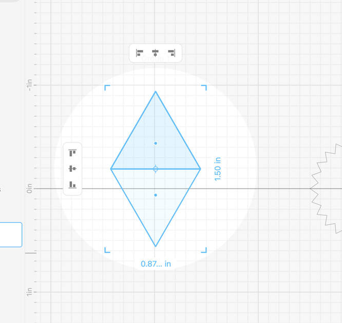
However, there was no parallelogram shape, or a way to change a rectangle to one. I tried to make it from lines, but it was too imprecise. Finally, I decided to connect two triangles to make one. First I connected them, then used the modify option to remove overlaps, and as a last step I did boolean union which resulted in a nice parallelogram.
|

|
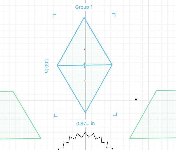
At the beginning I made some mistakes, and the triangles turned out to be off (Figure 32).
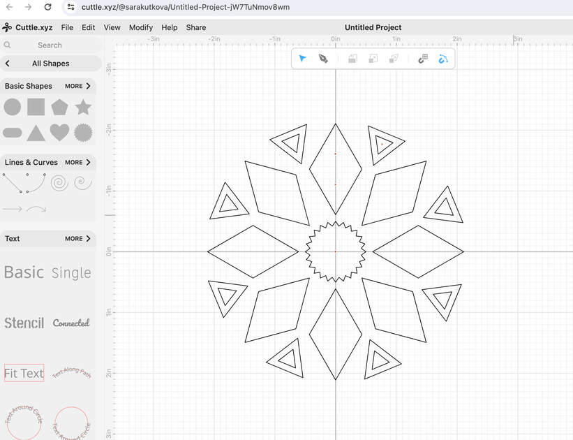
After I had the parallelogram shape, I used the rotational repeat to make many copies of it. I ended up using 8 copies instead of 6 from the sketch because I think it looks better. I then added the triangles, also did the rotational repeat with them and added an outline stroke.
The .svg file from Cuttle is at the end of this page in the Files section.
The only unfortunate thing about Cuttle is that at the free version, you can only have 5 projects.
Files
OpenSCAD train file - [Download]
Train .stl file - [Download]
SolveSpace pot file - [Download]
Pot .stl file - [Download]
Sun catcher .svg file - [Download]
![[Download]](https://gitlab.com/sarisko/fabacademy-files/-/blob/main/week2/sun_catcher.svg?ref_type=heads)