Week 11: Input devices
This week we are looking info reading sensor data, for example reading distance sensor, light sensor, thermistor… I chose to work with and accelerometer/gyroscope because I find it very useful.
Group Assignment
The page describing the group assignment for this week (probe an input device’s analog levels and digital signals) can e found here.
Arduino code
This website was my starting point when working with Adafruit accelerometer and gyroscope. It contains the pinouts, library installation guide and a very helpful example code.
The code I used was a modified version of a code mentioned above, it can be downloaded at the end of this page.
The test
I was not really familiar with the acc sensor (Adafruit LSM6DS3TR-C 6-DoF Accel + Gyro), so I first tried to work with the sensor on a breadboard to see if I can read it and control the LEDs.
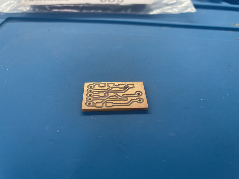
So the proof of concept works. Now I’ll make a custom PCB board for it.
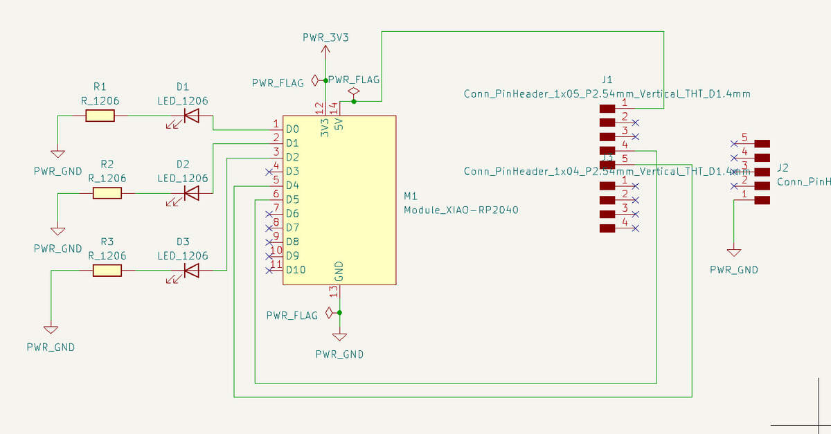
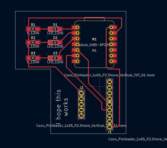
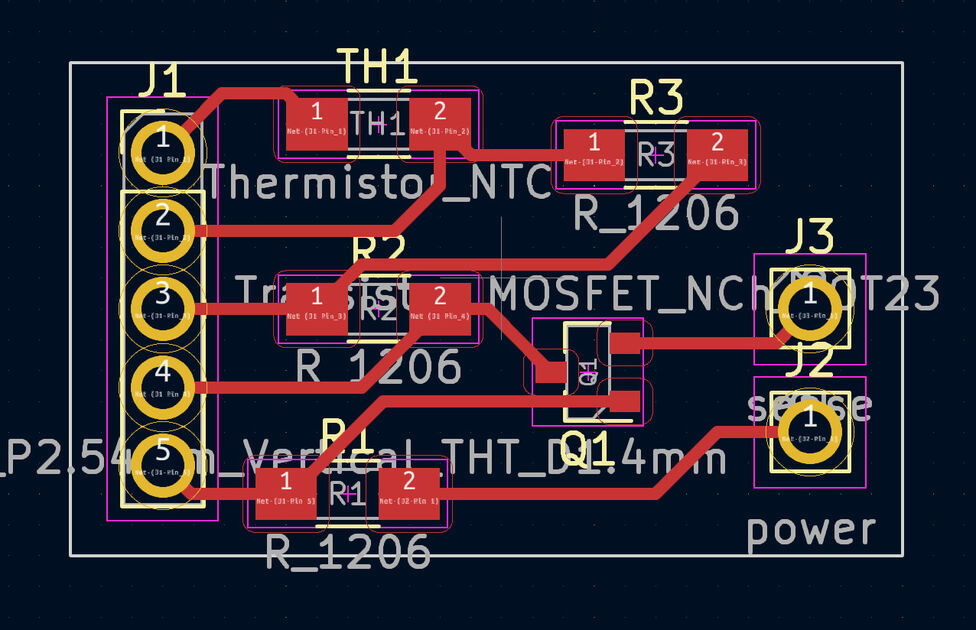
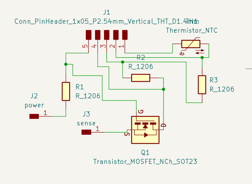
The board design
|
|
Download the KiCAD files at the end of this page.
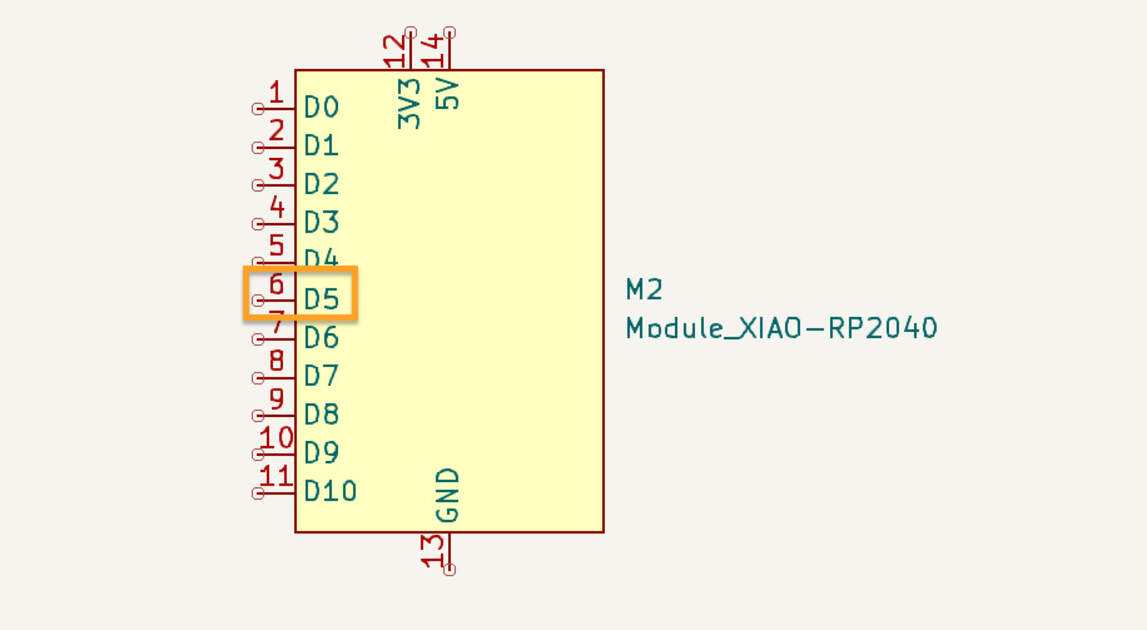
At first, I made a bad board - I was checking the documentation of the XIAO board, and was trying to connect the SDA and SCL with the accelerometer, so they can communicate. Unfortunately, when connecting the pins in the schematic editor, I connected the pins 4 and 5, not the digital pins D4 and D5 (as I was supposed to).
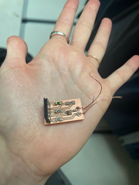
The final board
I wanted to make the LED’s light up at a certain angle, and then turn off below that angle. Honestly I was surprised how well it works, the precision was impressive. Can’t wait to work with it some more!
EXTRA: Making input devices
I took a smart wearables course where we explored the soft sensors, conductive properties or certain fabrics and also sustainability in SW industry. There was a final project, where we could choose a topic and make a case for some real life problem that could be solved using smart wearables.
We decided to explore outdoor activities such as hiking and peoples thermoregulation during them.
After making an initial user study, we found out that frostbite and overheating is a real issue that these people deal with.
An example use case is that you start your hike early in the morning, when it’s cold outside. Once you start walking up the hill, you quickly warm up, and if you don’t lose some layers, you might start sweating. That is not good, because as your clothes get wet it gets less insulating and will better transfer the coldness of outside to your body (e.g you will feel cold one you stop walking).
The solution we came up with is making a sweat sensor that would notify you that you started sweating.
This was a team project. My teammates were Pia Johansson and Liza Kuttappassery. On this page I will mainly talk about what I did, and if some of the work was done by my teammates I will credit them.
Exploring electronic water sensors

These sensors can detect water, and can be used for (for example) continuous monitoring of your plant, to check if it needs watering. We tested them, and chose of the designs.

We then made multiple sensors from various conductive materials, and tested the performance.
The for sensors we end up having were:
- Figure 7: sewing machine made sensor from cotton yarn
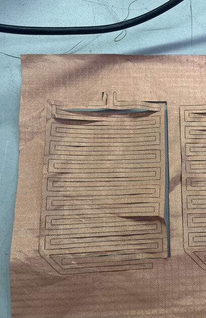
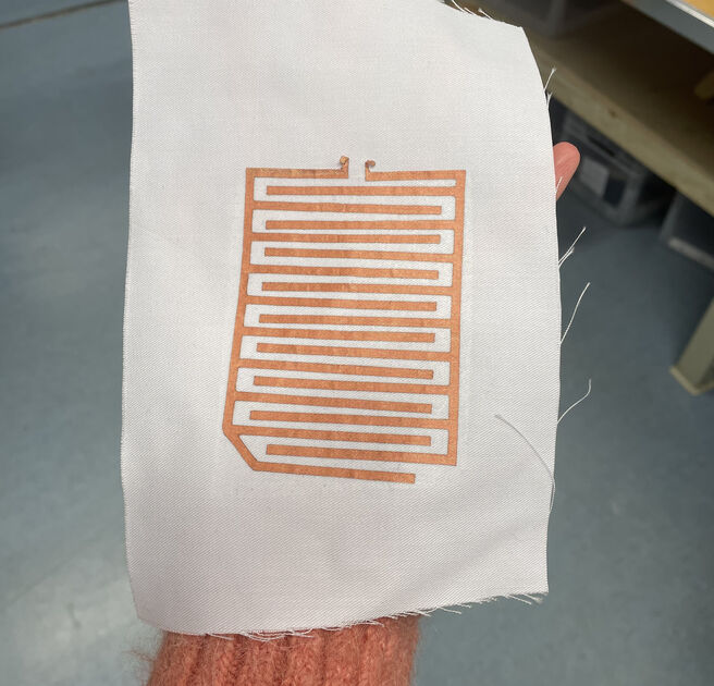
- Figure 8: laser cut copper fabric (then laminated onto cotton fabric)
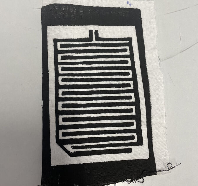
- Figure 9: screen printed sensor made from carbon ink (made by Liza and Pia)
- Figure 10: copper tape sensor (the tape was hand cut by Liza and then laminated on the cotton fabric by Pia)

|
|
|
|

|
They worked! The machine sewn sensor had the best performance.xs
|
|
|

|


|

|
Files
The Arduino Code for tiltmeter - [View]
The KiCAD files for tiltmeter - [Download]
The Arduino Code* for sweat sensor - [View] *Note that this code was heavily influences by online sources, mainly the sample code for the water level sensor and calculation for the temperature from the thermistor online
The KiCAD files for sweat sensor PCB - [Download]