Week 3: Computer-Controlled Cutting
Group Assignment
The page describing the group assignment for this week (kerf measuring, and testing different speed and power) can be found here.
Laser Cutting
This week we started to learn about laser cutting. We were introduced to the laser cutter in the lab, and our task was to try to play with the settings and cut something as a project.
Preparations:
Getting the laser cutter ready
- Safety first - ventilation must be on (maxed), and we need to make sure that the fire blanket and fire extinguisher are present. We need to watch the laser cutter at all times that it is on (there is also a small device that will ask you once in a while whether you are still present).
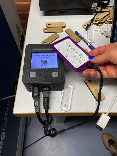
Figure 1: Device that beeps to check if you are present - Place the material in the laser cutter. The laser cutter can cut different materials -> we did the test cuts with cardboard as it is the cheapest one, then we tried the wood of different thickness
- It is important to calibrate the distance between the laser cutter and the material so that we get the best focal point. There is a metal thing attached to the laser with a magnet that can be freed, and it should be just touching the material below, so there is a bit of friction. If there’s not, we should adjust the laser cutter setting to either lift or push it down. NOTE: some laser cutters can do this automatically (even the one we have in lab, it was just broken for a bit) - when you are importing the material settings, there is an “Auto Focus” option there, which is “Off” by default, but we can set it to “Plunger”
Getting the design ready
- Prepare the design we want to “print” -> this should be a 2D design that will be cut out. Note that the product will be 3D, but the third dimension is just the thickness of the material we are cutting. The design should be in an appropriate (vector) format such as .dxf, .svg, .eps or .pdf.
- Open your design in Adobe Illustrator. Make sure all the lines you want to cut are 0.01mm thick.
- After we are satisfied with the design, we can try to “print” it (control P), which will open the print dialogue. There is a special add-on for the laser cutter, as seen on image bellow. Change the “Media Size” to Custom.

Figure 2: Adobe Ilustrator print - After selecting print, you should see the live image of what’s happening inside the laser cutter in a new program (at this point all the steps of “Getting the laser cutter ready” should be completed, and the laser cutter turned on) -> as seen on image bellow. If the camera doesn’t work, restart the laser cutter.
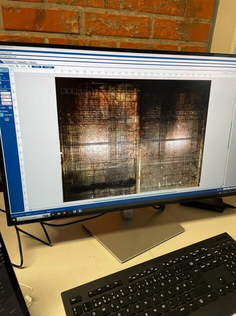
Figure 3: Laser cutter program - Place the piece where you want it on the image. Make sure it’s not too close to other edges (it can ruin the cut).
- Make sure that there is a vector and the engraving for the correct things.

Figure 4: Vector and Engraving - Select the right settings for the material you are using (there are pre-defined settings for different materials), adjust them if needed.
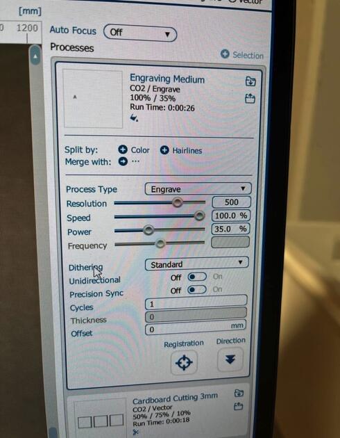
Figure 5: Different setting - You can select “Start cutting” on the computer. Then select the correct file name on the laser cutter display, and press play. The cutting should start now.
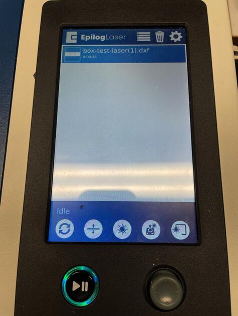
Figure 6: Press Play
Practical tips:
-
The laser cutter is connected to a computer next to it. It is nice to have the design prepared on a USB drive. The other option is to log in using the Aalto account, but that might take a bit of time
-
The strength of the engraving does not change the colour of the engraving, just the depth of the cut
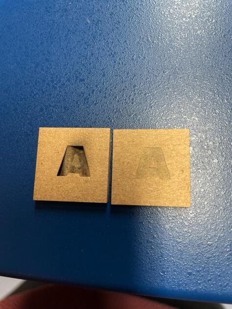
Figure 7: Engraving comparism -
Always open the laser cutter with both hands

Figure 8: Laser cutter opening
Kerf - What is it?
Kerf is the width of the material removed during cutting, which is determined by the laser beam’s diameter and the material being cut. Measuring kerf when laser cutting is important for achieving accurate cuts. How to calculate the kerf:
- Set up the laser cutter and ensure it is properly calibrated for the material you’re cutting
- Cut a test piece of the material you plan to use
- Measure the width of the test piece
- Calculate the kerf -> subtract the width of the cut piece from the width of the original material. Divide the result by two to get the kerf. For example, if the original material is 3 mm wide and the cut piece is 2.8 mm wide, the kerf would be (3 mm - 2.8 mm) / 2 = 0.1 mm
- Use the calculated kerf measurement to adjust your design
It’s important to note that kerf can vary based on the type of material being cut, the laser’s power, and other factors. It’s recommended to test the kerf for each new material or laser setting to ensure accurate cuts.
Documentation of the actual cutting
Cardboard squares
Our first cut was way out of focus -> the line was quite thick, and it was not possible to easily remove the squares from the cardboard plate. This was mainly because the material was bent, next time we can attach it using tape.

After we fixed that, the cut was way cleaner, so we tried to calculate the kerf. The image below is the second cut, three squares 30 mm x 30 mm without any adjustments. Together the length of these three squares was 89.4 mm.
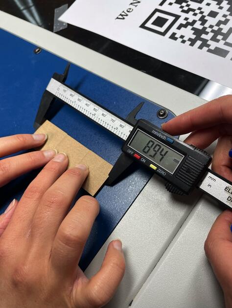
It seems like there was 0.6 mm cut away from the squares, 0.2 mm from each. So we made the squares 0.2 mm bigger, cut and measured it again. This time, the length was precisely what we would expect.

Bird house
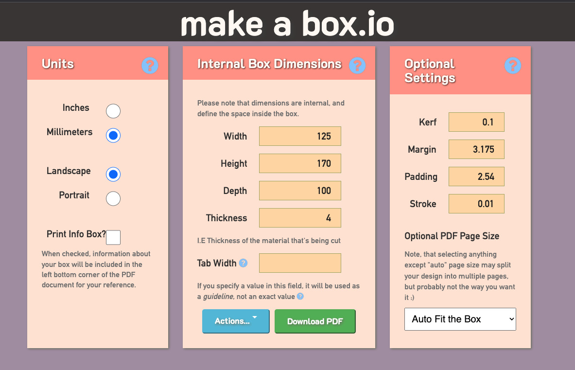
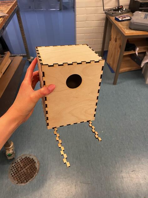
I was very keen on trying to cut something real, something useful (moderately fast because I was running out of time). So I decided to make a bird house (I do have a very small backyard where I can put it). Desperate times calls for desperate solutions, so I decided to use one of the online tools to help me create the box which I can later modify. I used https://makeabox.io/. I chose this one because it also counts in the kerf.

|
|
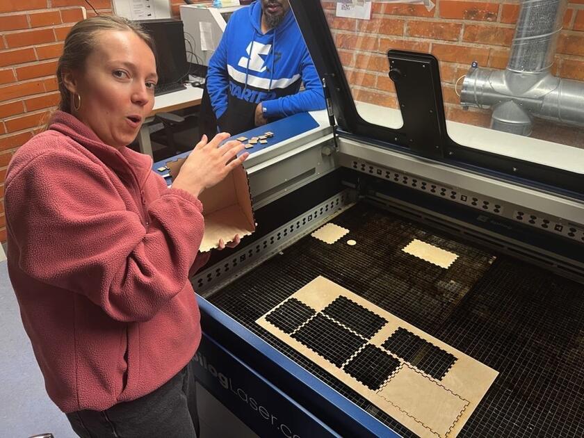
This was the first time cutting with wood - it was extra thrilling. I think the setting were just right as everything was cut nicely.

|
|
It was honestly a bit of a failure - the pieces did not hold together well, they were too loose. Later I found out that the wood we used was only 3 mm thick, not 4 mm (which I counted with in my calculations). However, at least it was somehow easily fixable, and it gave me the opportunity to use the wooden workshop. Solomon showed me around, and I used wood glue to make sure the bird house stays together.

|
|
At the end I attached some extra wood on the bottom, so the birds can rest there. I consulted by friend who is a bird ringer, and she advised to leave one side unglued (so it can be removed) because the inside of the bird box needs to be cleaned after each nesting season. She also confirmed that the wood glue won’t be toxic to birds. I would like to further improve the bird box, perhaps stick something nice to the side.
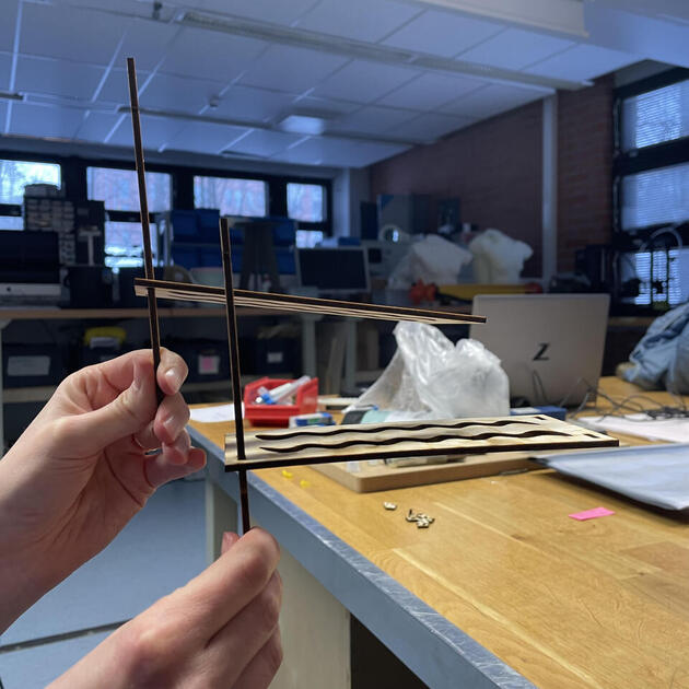
Mini shelf
During the CNC week, I would like to make a shelf for my “already used clothes” (clothes not dirty enough to go the laundry, but not clean so they can’t go back to the wardrobe). I made a design, but I am a bit unsure about the stability of it (and how it would look like), so I will make a smaller model (the size is 20% of the original model) using the laser cutter.
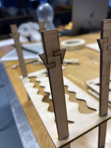
The design
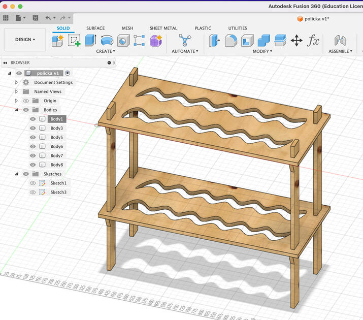
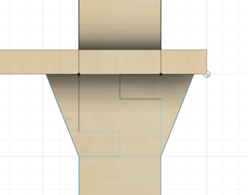
The most interesting/complicated part are the joins shown in Figure 19 that are supposed to hold the upper part of the shelf. The idea is that the lower desk is going to “slide through” the leg, and then the asymmetric pieces will be added to it that would hold the upper shelf in place. I wanted it to look nice, like a part of design. You can also notice the right angles between the leg and stoppers for better support.
|

|
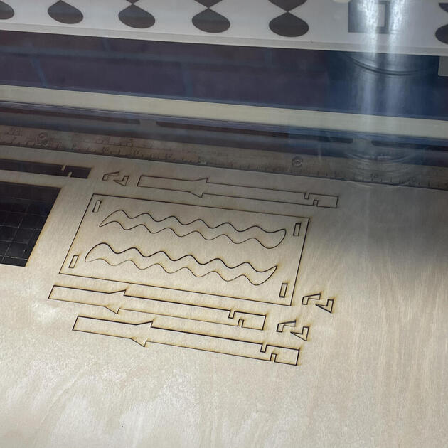
Test cut
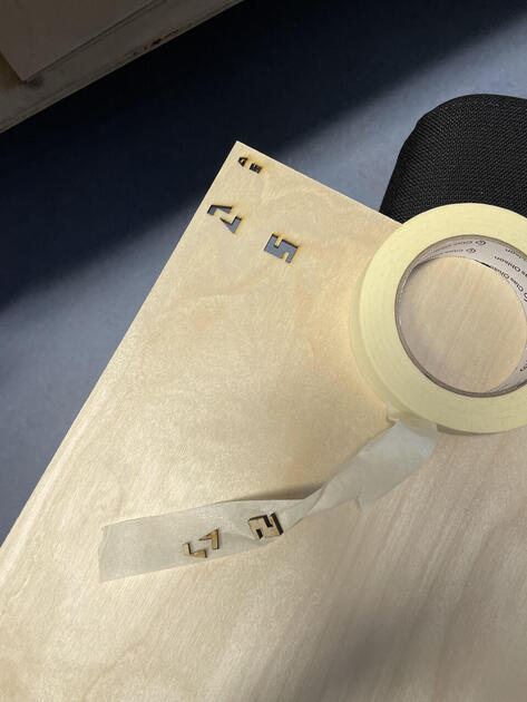
First I tried to cut just the joins (with small part of the leg to save space). The test pieces were so small that after the cutting I had to tape them to the plywood otherwise they would fall through the metal grid of the laser cutter and be lost forever.
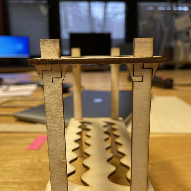
Assembling
Some close up pictures of the joins/stoppers. After I managed to improve the fit, they worked fine and looked nice.
|
|
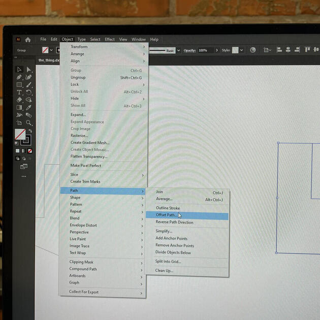
Adjusting the fit
After cutting the test stoppers, I actually also cut three sample squares to calculate the kerf. It turned out to be 0.1 mm. Normally I would modify the parametrised design in Fusion 360,but Fiia showed me a convenient trick of how to make the design bigger/smaller everywhere at once (to include the kerf). In Adobe Illustrator first select the object you want to scale (make bigger/smaller), then Object->Path->Offset Path. You will be asked how much offset you want to create, and it will make a new line for you. It doesn’t work well with sharp corners, but I didn’t mind, and you can’t spot the difference in the finished product. Also, one should not forget to delete the original lines, otherwise the laser cutter will cut them as well.
Then it was time for the second cut! The real speed of the laser cutter we have at lab:
In the second iteration, I wanted to minimize wobbling of the shelf by making the leg/horizontal desk connection tighter. On the Figure 26 bellow, you can see both the first and second “generation”. The top one is the first one, and one can notice that because the hole is too big, the gravity makes the shelf “lean down” at a smaller angle. The leg-shelf fit is better in second iteration, so we can see almost a right angle between them.
There was also a third (the final) generation, where the fit was even tighter.
Finished product
Happy with it. The design can definitely be improved (it’t now not wobbly, but perhaps a bit askew), but I tried to mainly focused on getting comfortable working with the laser cutter.

Vinyl Cutting
We have a Roland GX-24 vinyl cutter at the lab. I will make some fish stickers!
I refered to the FabLab Aalto wiki page for more information about the vinyl cutter.
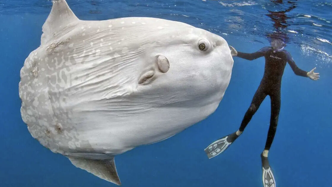
I used ProCreate to make a fish - Ocean sunfish. That fish is big, does not really use its back fin for swimming, and can survive diving (and resurfacing) from deep waters.

|
|
Bellow is a .png file I exported from the ProCreate. However as it is a raster software, we had to convert it to a vector format (as that’s what vinyl cutter accepts).

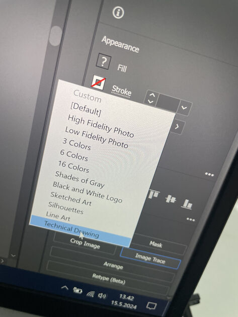
I had a huge help from Saskia - she showed me how can I convert the .png to vector lines using Adobe Illustrator. We “traced the image”, and selected the technical drawing - this is because we wanted it to make a single lines out of it, not shapes. We also then did few minor changes and grouped the elements.
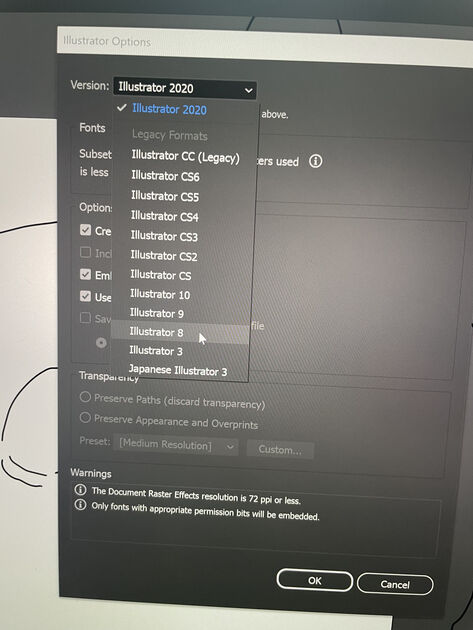
Then as we were saving the newly made vector image, we saved it with the older version of Illustrator - apparently it works better (it’s simpler and better to understand for the vinyl cutter).
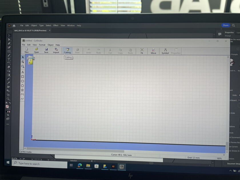
We then opened the CutStudio program, and imported the .ai file there. I then scaled down the fish so it’s not too big.
Preparing the vinyl cutter
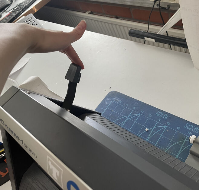
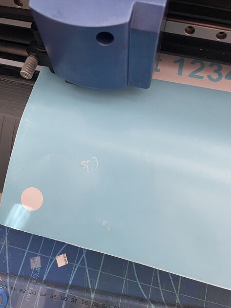
There is a lever on the back of the vinyl cutter that lifts the wheels, so you can insert the vinyl sheet inside.
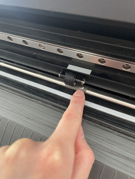
The wheels push the vinyl sheet back and forth (y-axis), and the cutter can move right to left (x-axis). When we insert piece of the vinyl, we can move the wheels, so they will be on the side of the piece - but they should always be above the “friction” pads, so the vinyl sheet will move when they rotate.
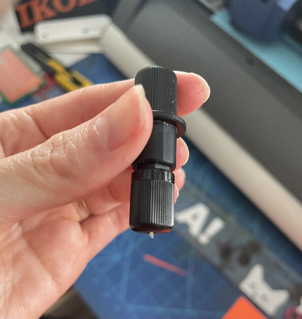
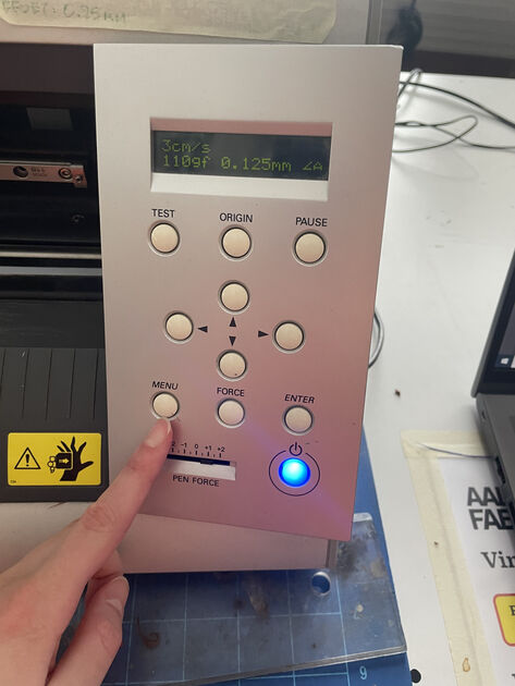
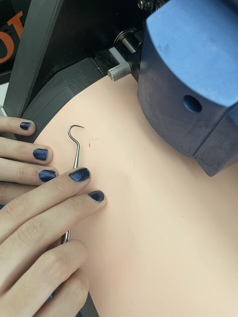
We can also adjust the cutting blades’ (on Figure 36) force and speed - one at the time.
The vinyl cutter had a small interface. After we insert the vinyl (and secured it by pulling the back lever), we can select whether we inserted a roll or a piece. If it’s a piece, the cutter will measure the size of the piece, and set up some origin not too close to the edges. After this we can move the position of the place by pressing the arrows (we can also set a custom origin). Then we can press “test”, which will do a small test cut. This is useful because we can then see if the blade cut thought the material - if not (or too much) we can adjust the settings.
The machine is sometimes not responding - it shows to be useful to hold the button for a bit longer, and then the machine will register it.
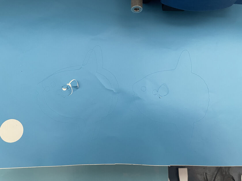
The test worked! But it was at that point we realized that we used the stencil vinyl, which is not really the sticker vinyl we wanted.
|

|
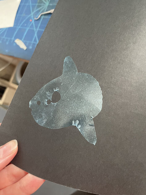
I also made the fish (Figure 40), however it was not so great. I would call it a fail -> mainly because I used a wrong side of the transfer tape.
However then we used the good “sticker making” vinyl, and the fishes look nice (well at leart the one on right, the two left ones collided). :) I will find some nice place for them <3
The final boss of my vinyl cutting experience was making a Ocean sunfish merch, e.g. cutting the fish out of heat transfer vinyl and then ironing it to some shirt.
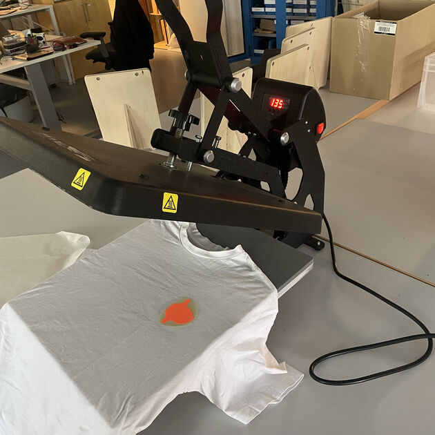
Instead of iron we have a heat press in the lab. Heat press is better than iron, as it measures the temperature and time, and has the heat more evenly distributed.

|
|
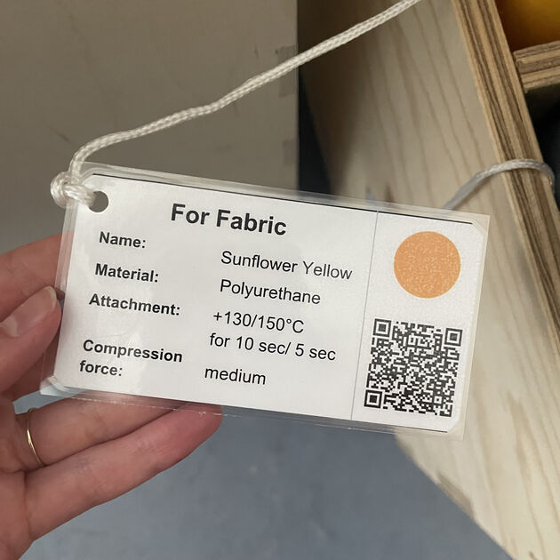
The vinyl sheets have these handy labels, so I could check the temperature and time it should be in the heat press. It is not exactly the label for the vinyl I used, but it was similar one.
From what I understood, this vinyl consists of 3 parts - glue (that will be touching the fabric), color (what will you see when looking at the T-shirt) and a protective plastic layer. We cut the vinyl from the glue side, then cut it out from the roll (with scissors), and then peel the glue with color surrounding the design so just the protective layer stays (Figure 44). We put this onto the T-shirt from the glue side - we can notice that the design will be mirrored compared to the original design (what was in the CutStudio) - you need to be careful about this in case you have some designs including text.
Then we put the baking paper from both sides - to protect the heat press, and also the glue will melt, so we don’t want the front and back of the T-shirt to stick together.
I then closed the lid - 150 degrees Celsius for almost 10 seconds. I carefully removed the T-shirt from the heat press, and waited for it to cool down. Once it was room temperature again, I carefully removed the protective plastic layer from it. And it’s done!
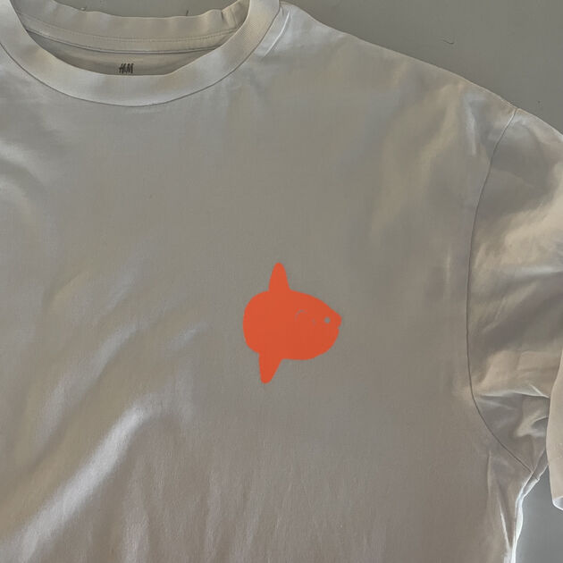
Final T-shirt looks nice! I hope it will survive washing in the washing machine.
Final notes
Kerf explanation influenced by Chat GPT.
Met Jeti at the lab - hopefully I made a good first impression even though I didn’t give him any treats.
Files
Birdhouse .pdf - [Download]
Shelf dimenstion .dxf - [Download]
Shelf Fusion 360 file .f3d - [Download]
Ocean sunfish design vector file .ai - [Download]