Week 6: Embedded Programming
This week we worked on embedded programming. We were given a Seeed XIAO RP2040 board from Seeed studios. Overview: https://wiki.seeedstudio.com/XIAO-RP2040/
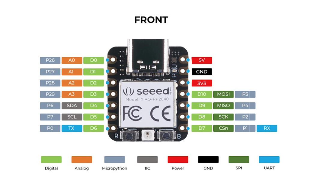
Group Assignment
The page describing the group assignment for this week (demonstrate and compare the toolchains and development workflows or alternative embedded architectures) can be found here.
Soldering
The useful tutorial to soldering headers here.
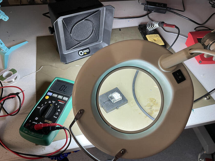
I did solder some stuff before, but I am still need more practising. Should’ve watched more tutorials. I like that there are quite a few tools in the lab (such as flux pen and desoldering braid), was happy to get to try all of them.
|

|
Before I started soldering, I turned on the fan. After a bit, I had a first attempt at soldering the headers, but it turned out not ideal.
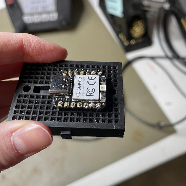
Therefore, (with Yu-Hans help) I used the disordering braid to remove the excessive tin.
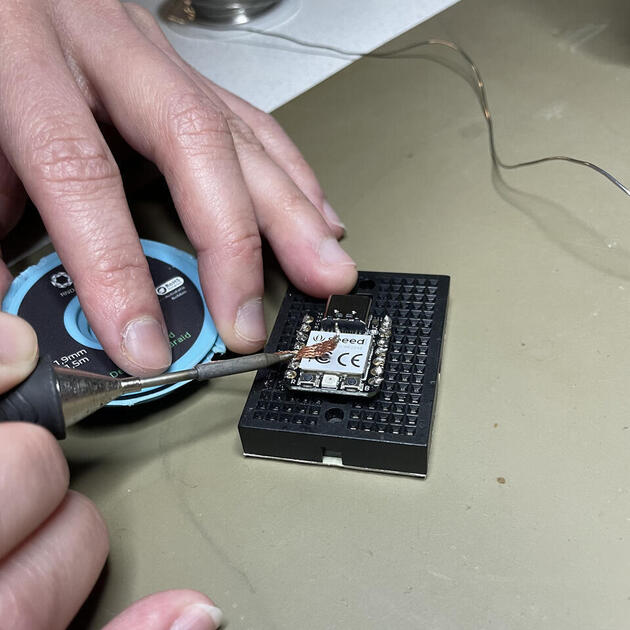
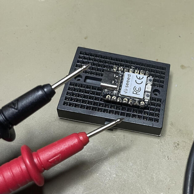
After this I managed to solder the pins (although not beautifully). I now understand that the tin is supposed to cover the “golden” area where the pins are, so they are securely in place. To check that there is no short circuit, I used the voltmeter (the resistance setup) to check all the neighboring pins.
|

|
Programming
I wanted to use Arduino to program the board, however for some reason on my computer I couldn’t find the Raspberry Pi Pico/RP2040 - I will solve this problem later, but for now let’s try using the MicroPython and the Thonny IDE.thonny
Installing Thonny:
brew install --cask thonny
I haven’t used MicroPython with a board yet, so it’s a nice learning experience. I am not sure if I would use it in production as it is still Python - too big for some microcontrollers, somewhat clumsy and not real time. But its nice for testing, and I do believe it is easier to program. Documentation can be found here.
The initial setup was a bit tricky, and can be found here. Interesting steps were that the board should be booting when connecting to the computer, and then how MicroPython is installed to the board.
First program
To showcase that the board works, and it’s correctly set up, I tried to run one of the default programs (something like blink in the Arduino library).

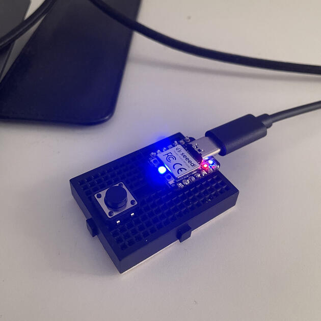
# this is a default code to test the connection with RP2040
from ws2812 import WS2812
import utime
import machine
power = machine.Pin(11,machine.Pin.OUT)
power.value(1)
BLACK = (0, 0, 0)
RED = (255, 0, 0)
YELLOW = (255, 150, 0)
GREEN = (0, 255, 0)
CYAN = (0, 255, 255)
BLUE = (0, 0, 255)
PURPLE = (180, 0, 255)
WHITE = (255, 255, 255)
COLORS = (BLACK, RED, YELLOW, GREEN, CYAN, BLUE, PURPLE, WHITE)

led = WS2812(12,1)#WS2812(pin_num,led_count)

while True:
    print("Beautiful color")
    for color in COLORS:
        led.pixels_fill(color)
        led.pixels_show()
        utime.sleep(0.2)
More sophisticated program
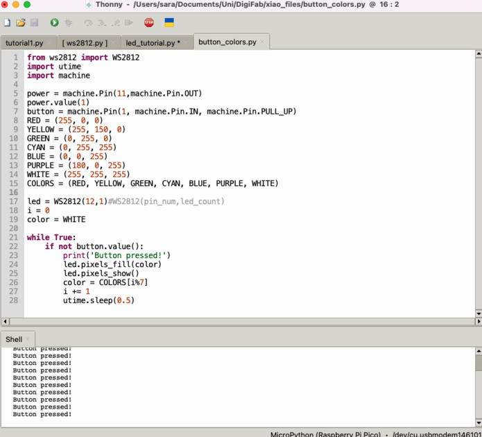
I made a program that the colour changes when you press the button.

from ws2812 import WS2812
import utime
import machine

power = machine.Pin(11,machine.Pin.OUT)
power.value(1)
button = machine.Pin(1, machine.Pin.IN, machine.Pin.PULL_UP)
RED = (255, 0, 0)
YELLOW = (255, 150, 0)
GREEN = (0, 255, 0)
CYAN = (0, 255, 255)
BLUE = (0, 0, 255)
PURPLE = (180, 0, 255)
WHITE = (255, 255, 255)
COLORS = (RED, YELLOW, GREEN, CYAN, BLUE, PURPLE, WHITE)

led = WS2812(12,1)#WS2812(pin_num,led_count)
i = 0
color = WHITE

while True:
    if not button.value():
        print('Button pressed!')
        led.pixels_fill(color)
        led.pixels_show()
        color = COLORS[i%7]
        i += 1
        utime.sleep(0.5)
Serial connection
As mentioned, I had problems with Arduino. It turns out it was because I forgot to add Additional Boards Manager URLs in Preferences (as shown in this tutorial).
Now, using Arduino interface, I made a simple command like code where the commands I was writing on the computer where changing the LED color on the XIAO board to some pre-defined colors.

#include <Adafruit_NeoPixel.h>
int powPin = NEOPIXEL_POWER;
int neoPin = PIN_NEOPIXEL;

Adafruit_NeoPixel pix(1, neoPin, NEO_GRB + NEO_KHZ800);

void setup() {
  pix.begin();
  pinMode(powPin, OUTPUT);
  digitalWrite(powPin, HIGH);
  Serial.begin(19200);
 }

 void loop() {
  while(Serial.available()>0){
    char message = Serial.read();
    Serial.print("Received: ");
    Serial.println(message);

    if (message == 'r'){
      pix.setPixelColor(0, pix.Color(255, 0, 0));
      pix.show();
    } else {
      if (message == 'y'){
        pix.setPixelColor(0, pix.Color(255, 150, 0));
        pix. show();
      } else {
        if (message == 'g'){
          pix.setPixelColor(0, pix.Color(0, 255, 0));
          pix.show();
        }
     }
    }
    delay(200);
  }
 }
A more advanced example where the board is interacting with an application through the REST API is covered in Week 14 - Interface and Application programming.
Simulated board - Wokwi
I did some experiment with simulated boards, with Wokwi - documentation here. In my final project I will be using servo motors and Xiao ESP32, and there were some problems with it, so let’s see if I can simulate it.
I found an example with Xiao ESP32 here, and an example with servo motors here. I will try to combine them.
I was curious to see is the simulation is going to work, and if not what will be the advice from Wokwi. In general, the simulation should not work as the PWM on servo require 5V, and the Xiao GPIO only supplies 3.3V, and one needs a level shifter to operate the servo with a Xiao. The simulation I made is here -> https://wokwi.com/projects/423337044369312769
However, I was surprises to see that the simulation works (the servo is turning). So naturally, I started to be curious why is that. Perhaps they have the servo designed differently, and it only needs 3.3V? Or is there a “mistake” in the Xiao files and the default I/O ports are 5V?
Based on their servo documentation, the simulated servo should require 5V. The servo documentation also contains a very nice explanation on how PWM works.
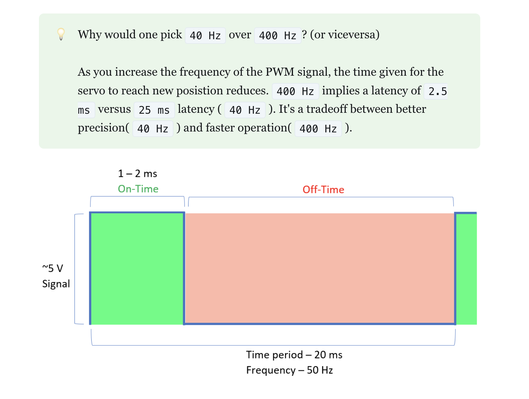
It seems that pins on the Xiao are defined as 5V pins, and that seems to be a default for I/O pins in the Wokwi setup. Good to know…
