Week 16: System integration
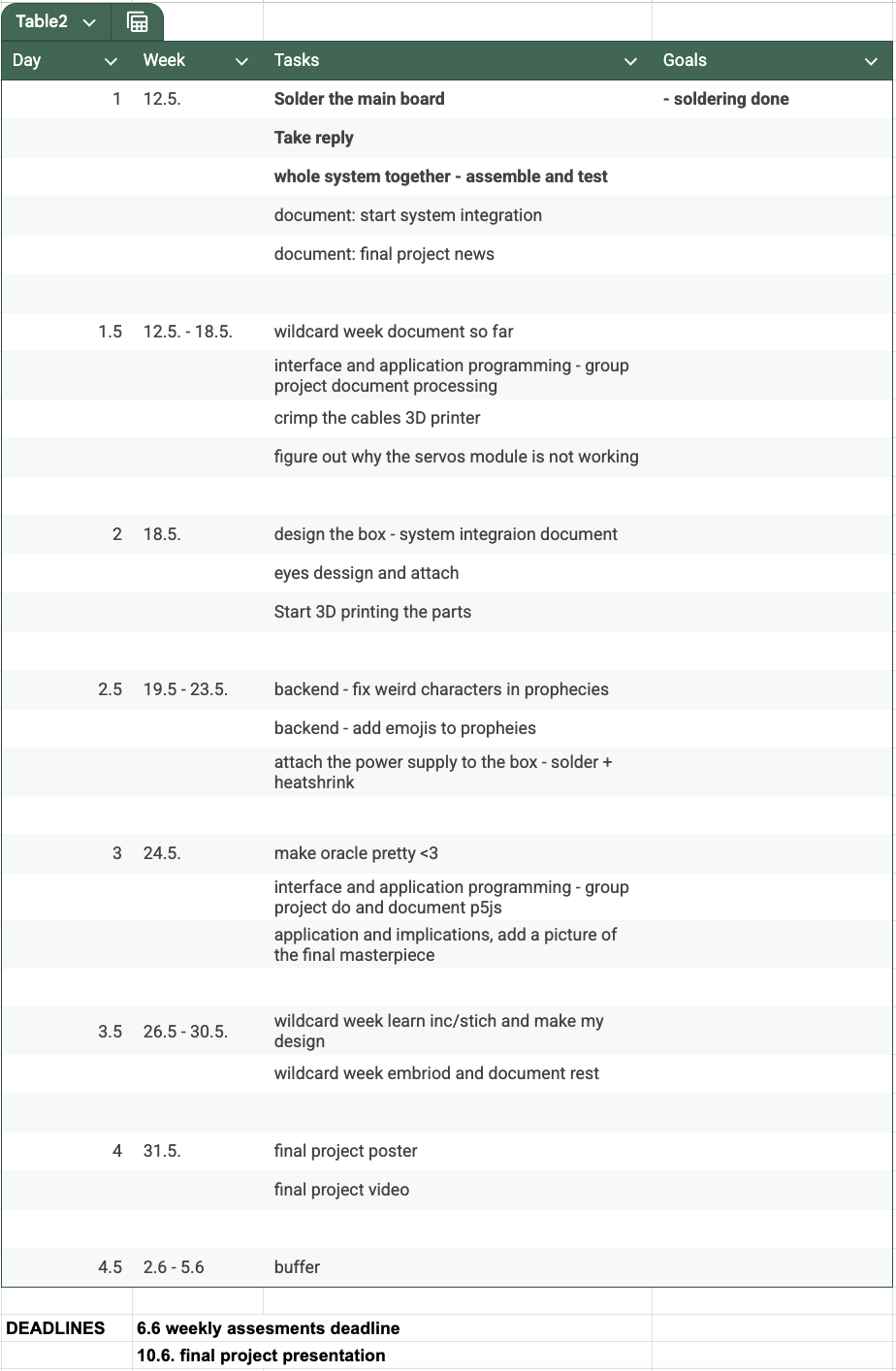
To make sure my project won’t suffer from approaching deadlines, I made a schedule for the remaining time left in my FabAcademy which includes all tasks I should still do.
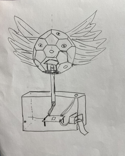
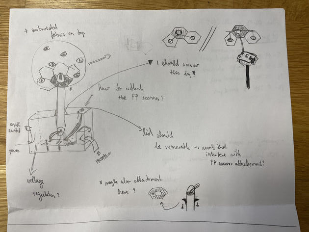
I also made a sketch of how I’m imaging my project will turn out like. This helped me identify all the remaining tasks.
|
|
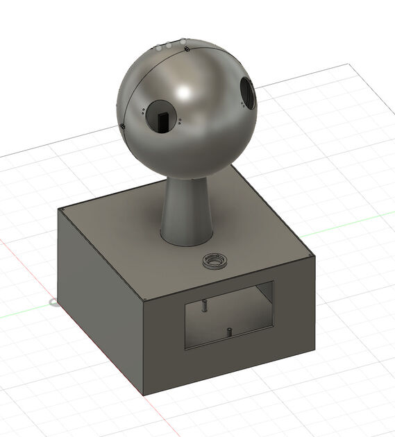
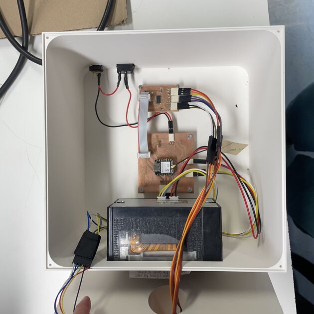
In the system integration week, I aim to make a nice enclosure for my electronics, one where all the PCB boards and electronic components will be securely attached. As Neil mentioned during the Global lecture, I should be able to shake my project without consequences.
So how will I make sure my system will survive that?
Mechanical design -> Fillets
Making sure all my sharp edges have fillets makes my design more robust while saving filament as the walls don’t need to be as thick for the same level of sturdiness.
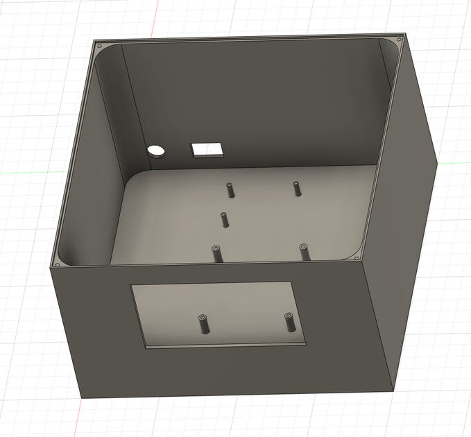
PCB mounting
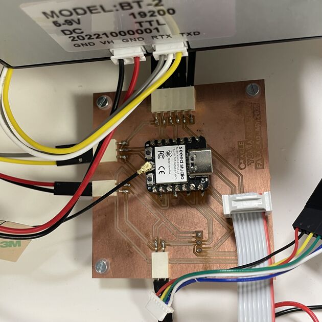
When designing my PCBs in KiCAD, I made sure to include holes at the edges for PCB attachment. Kris recommended using plastic screws, however as I didn’t use any bolts I ultimately decided to use the metallic ones as they hold better in the PLA holes.
The reason for not using the metallic screws can be that they are conductive, and it could perhaps mess us with your circuit. In my circuit I was not using to area of board as the ground, and the screw would only touch the non-conductive PLA, so I don’t think it matters. But it is a good thing to keep in mind for future projects.
Wiring
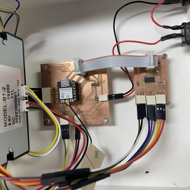
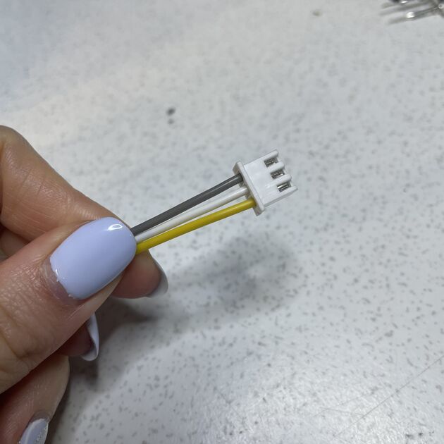
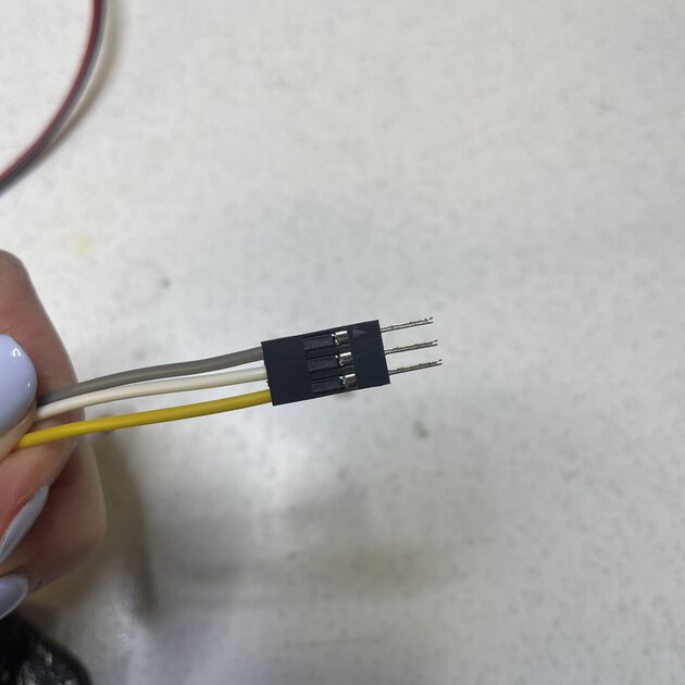
I crimped multiple cables to make sure they hold together well. I also used the “bus” cable between the two of my boards, and it looks and works great, much better than having a bunch of cables in between.
During the review of my final project Neil commented that I should make sure that the “bus” cable is properly attached, and that it may be hard to do by hand. If I fail to properly pierce the cables, it might result in unstable connections, and may cause issues that are hard to debug. There is also a special connector crimping tool for that.
|
|
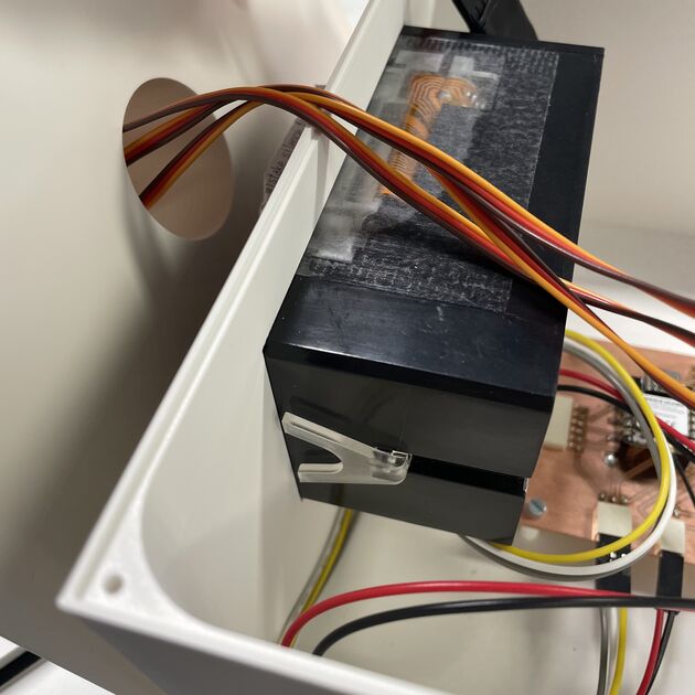
Self alignment and strain relief
I tried to use the components that have built in strain relief, or can be attached securely.
The printer has these little plastic “legs” that are secured in place with a screw. I designed the hole to fit the printer, and then attached it in place using the “legs”. Side note: The paper loading feature is in the front of the printer, so when the printer runs out of paper, I reload it from the outside. No need to open the box!.
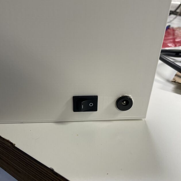
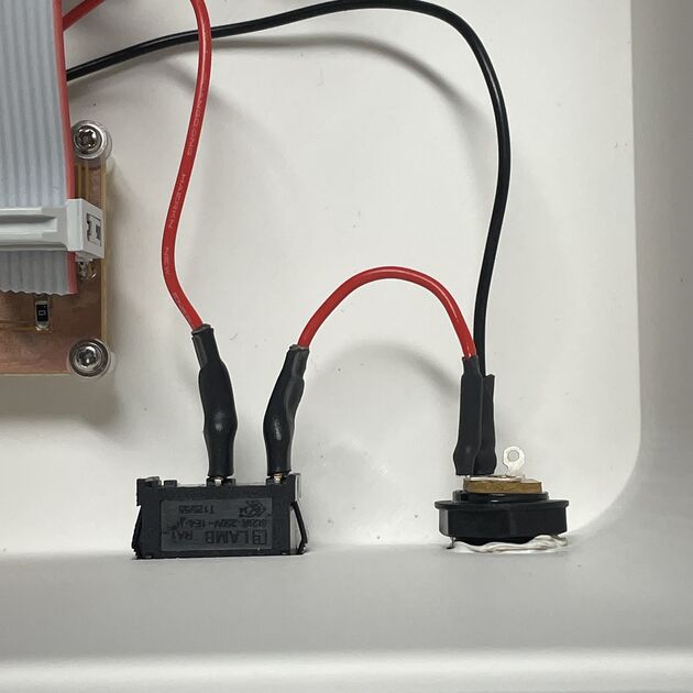
The power control is an adapter that is screwed to the wall of the box. The ground it directly connected to the PCB, however the 7.5V goes through switch. This is probably one of my favorite elements -> it is easy to make, but it brings me so much satisfaction to hear the click when it turns on. It is also quite useful because then I am uploading the code to the Xiao, it is better to not power it both from computer and from external power supply as the same time - and I can just use the switch to turn it off! So nice and easy.
Side note: I also made sure to wrap the cables in heatshrink (or some other ones in electronic tape). Under any circumstances I don’t want to have short circuit there.
|
|
I am trying to have all the elements attached in the case, so that when I shake the Oracle, I won’t hear any rattling.
Fault prevention
I use level shiftier to make sure the voltage is 5V for the servos. It worked even without the level shifter for one servo, however because I am using 3 of them (plus other components), and because it is a good practice to follow the recommended specifications for given component, I included one.
Environmental impact - Reusability of components
I tried to not be wasteful while designing and building my prototype. The biggest waste were probably the failed prints (though I am consoling myself that PLA is biodegradable in industry conditions).
The electronic components can be reused in future projects if necessary - none of them is attached permanently (with strong glue for example).
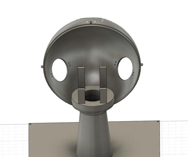
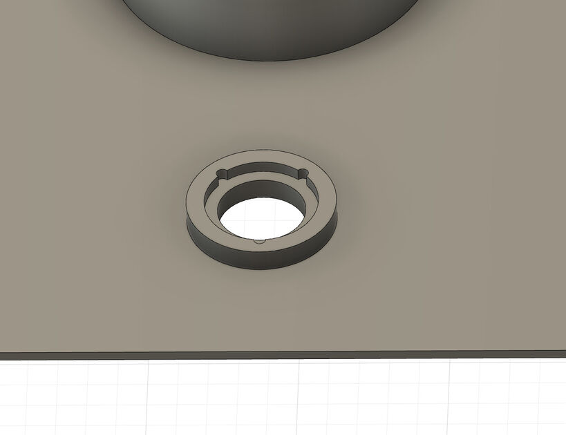
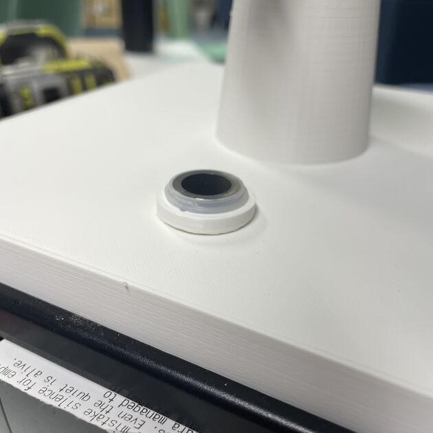
I even made a spacial case for the fingerprint scanner because it had a unique shape and would be difficult to attach otherwise.
|
|
Testing
I also tried the “longevity” test, where I left my prototype running for prolonged time, and there were no problems with it for now.
I was at fist a bit skeptical, because in my code I am using unsigned long micros(), which overflows after a bit more than an hour, but after it overflows it resets to zero and increments again. With a help from Chat GPT I made sure to take that into account, and compare it with millis() to detect the overflow.
Modularity
I divided my software into the main .cpp file, and also prophecies.h file where I store all the angelic names and prothecies.
I am also using different PCBs for different parts of the system - the main one with the microcontroller for power supply, fingerprint scanner and printer, and a second one for stepper motors.
Final notes
I had run with my prototype on multiple occasions (to catch a bus for example), and it survived! I therefore believe it passes the “shake test” :)
Files
Case file - [.f3d]