individual assignment:
add an output device to a microcontroller board you've designed,and program it to do something
group assignment:
measure the power consumption of an output device
As for the grouop assignment the work can be found here.Now let us deal with the individual assignment:
The goal is to program a microcontroller and select an output device that does what we programmed it to do,
through the process of allowing the controller to command what the device does.
There are different types of output devices in electronics systems.
Examples of things that can play a role of an output device:
Sound: Loudspeaker, buzzer
Light: Lamp, LED
picture: screen, Display
motion: Motor (DC motor, stepper motor, servo motor,..)
If we look closely, we see that output devices are those that convert electric energy into other forms of energy.
for example, electric into light. Hence they classify as transducers.
OUTPUT DEVICES
In this week ,Neil gives an introduction about the output devices and give many examples of output devices that we can try.As assignment we have to connect an output device to a board that we designed.Programme it and make it work.So this week i decided to make a board which can run a speaker.
But this time I learned many otherthings like Ripup to make rooted wires unrooted.I also learned how to use the design rules. and I learned auto rooting which is very easy to click a button.
An output device is any piece of computer hardware equipment which converts the electronically generated information into human-readable form[1]. In brief, output unit is responsible for providing the output in user readable form[1]. It can be text, graphics, tactile, audio, and video. Some of the Output devices are Visual Display Units (VDU) i.e. a Monitor, Printer, Graphic Output devices[2], Plotters, Speakers etc. A new type of Output device is been developed these days, known as Speech synthesizer[3], a mechanism attached to the computer which produces verbal output sounding almost like human speeches
SPEAKER
For this week I used a speaker as an output device.
Regardless of their design, the purpose of speakers is to produce audio output that can be heard by the listener. Speakers are transducers that convert electromagnetic waves into sound waves. The speakers receive audio input from a device such as a computer or an audio receiver
This input may be either in analog or digital form. Analog speakers simply amplify the analog electromagnetic waves into sound waves. Since sound waves are produced in analog form, digital speakers must first convert the digital input to an analog signal, then generate the sound waves. The sound produced by speakers is defined by frequency and amplitude. The frequency determines how high or low the pitch of the sound is.
In the week of electronic_production i designed a programmer and now i will make a board on which i will mount
an ESP32 controller, to which i will send codes through an arduino IDE.
So i used a board that has a the capacity to be connected through UART to connect to the computer...
This board has also analog and digital pins i can use for both inputs and output.
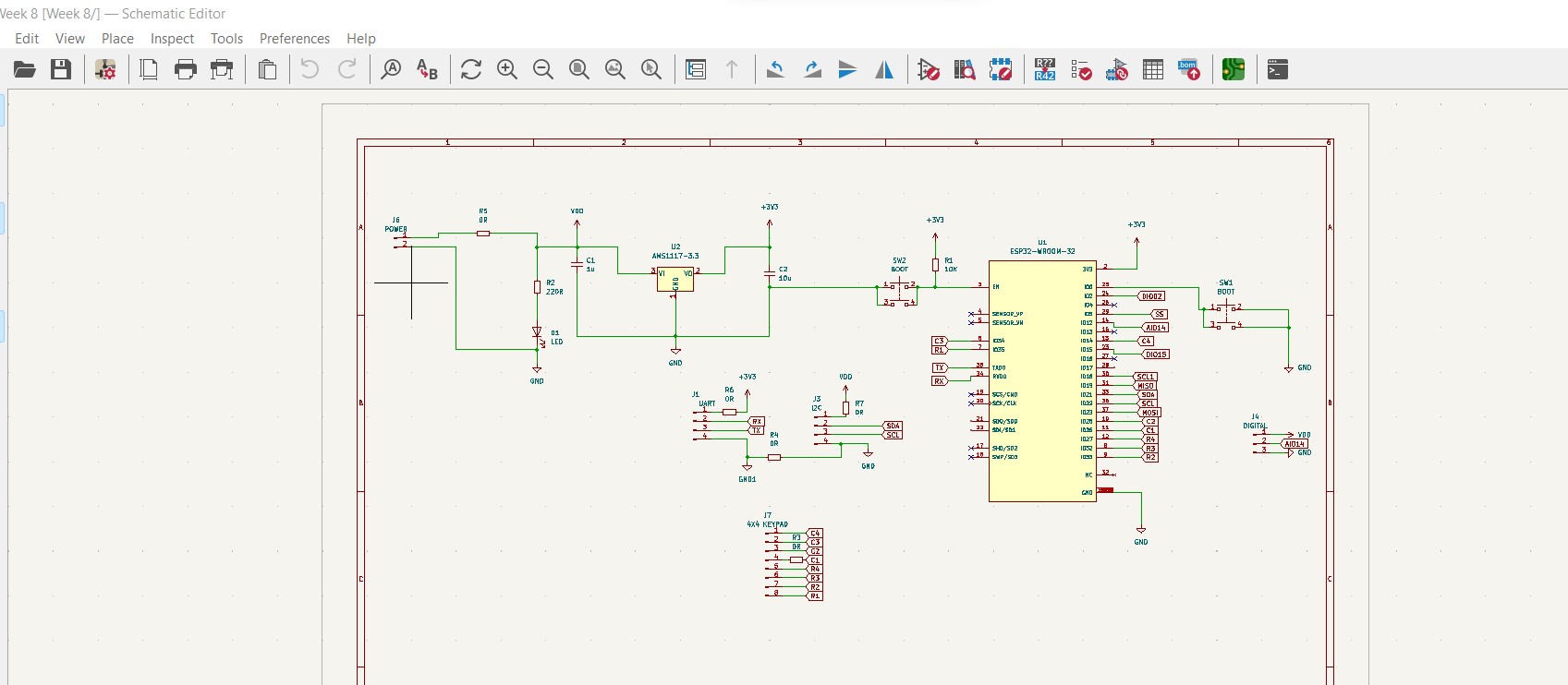
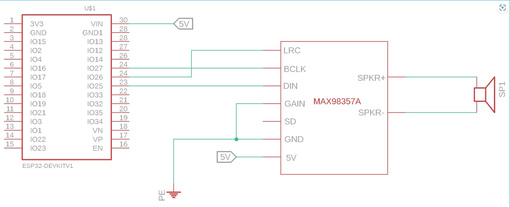
The schematic is like this:
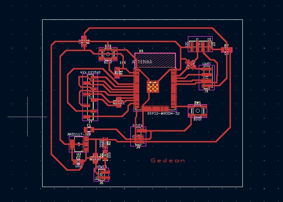
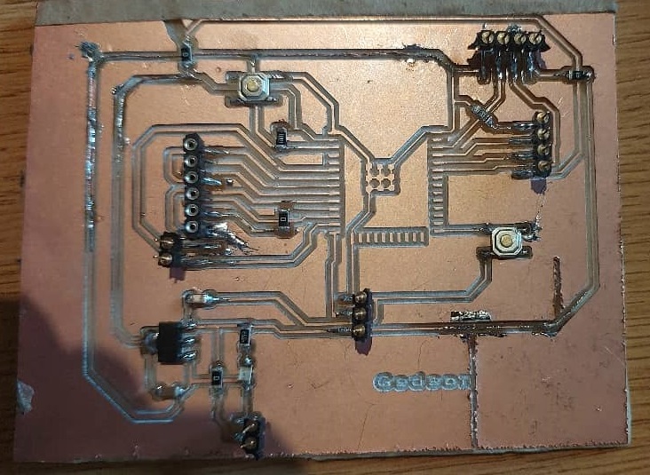
The PCB is like:
As you can see there are many 0 ohm resistors to try and avoid short circuits since there was manual routing of traces.
Having to use only one side of the board makes it very tricky of a job.
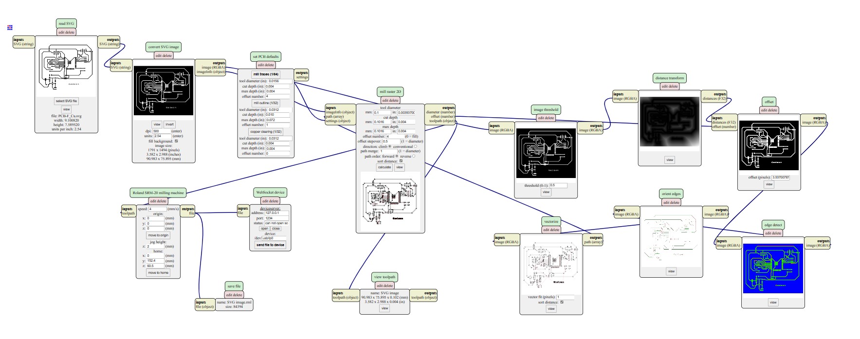
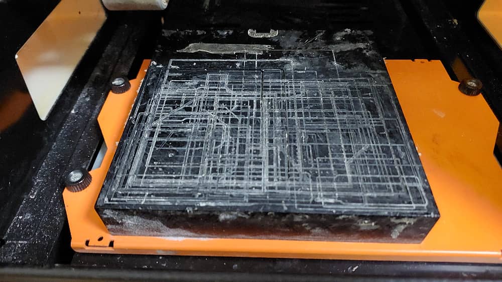
Using mods, i generated files for the SRM 20 milling machine.
I repaeted the process but now i used a different tool for the edge cuts.
However, since the lab has no 0.1mm bits i was obligated to use 0.2 and with it is hard to get clear lines.
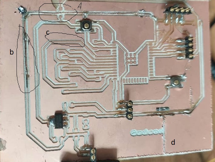
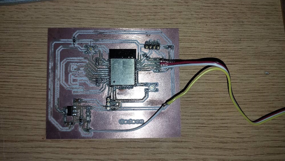
Here is how the board looked like when i started soldering:
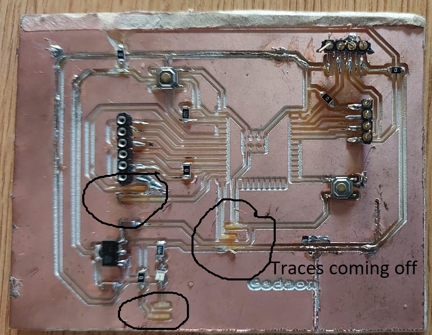
The parts that i marked with letters are the traces i had to use a wire to re-do.
That seemed tedious but i enjoyed not wasting a whole board, so i found another way.
I used a multimeter to test if there are any unwanted conncetions.
I found the board fine, it will work.
As i progress soldering:
There remains an ESP 32 controller to be soldered on. I will add it in when i get it, since we currently are low on that stock.
In the meantime, I found out that the traces are coming off
Despite the fact that the board also looked bad, un clean in a sort, I decided to print the same circuit again.
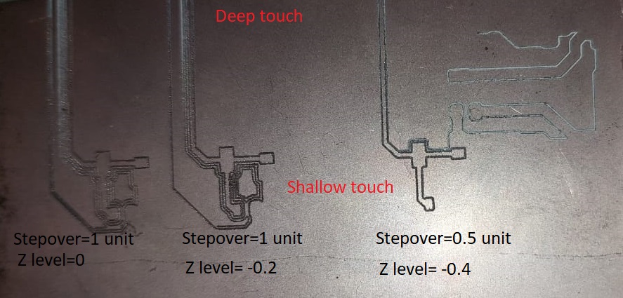
Things i changed:
The tool: I now used the mill bit of 0.1
The offset number: i now used 4
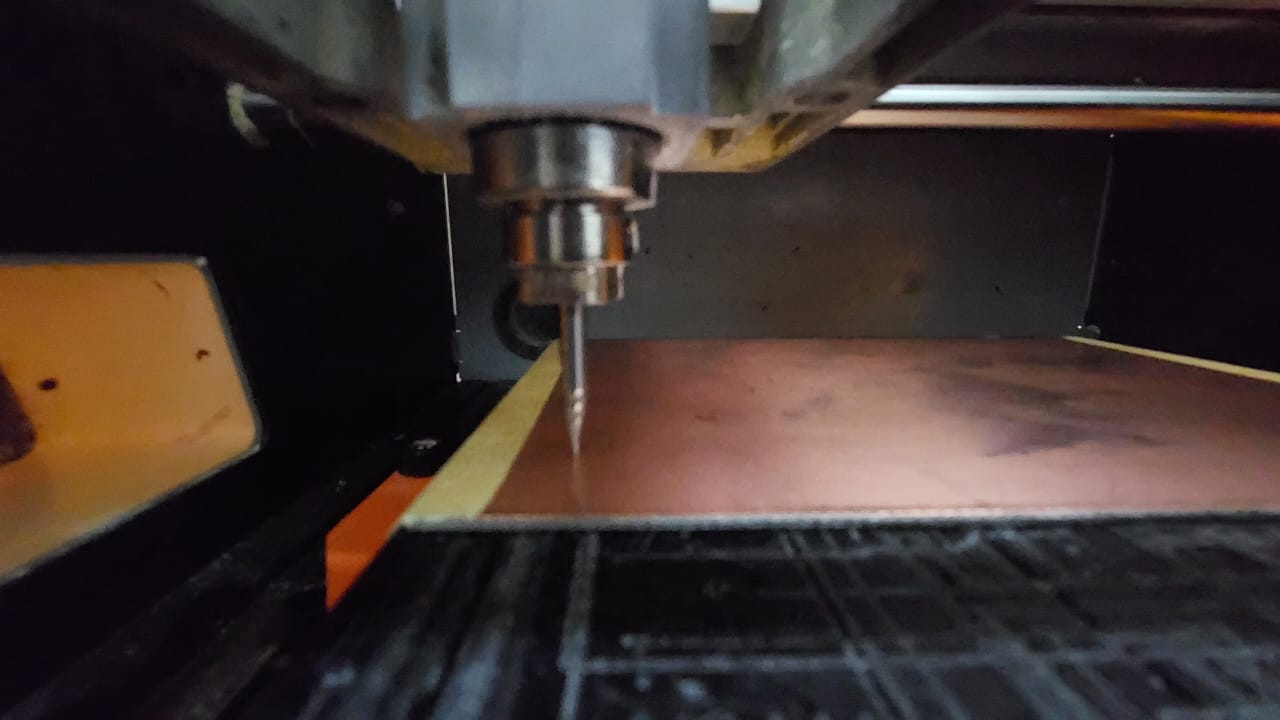
For the fist tries, there were errors as indicated in the picture below:
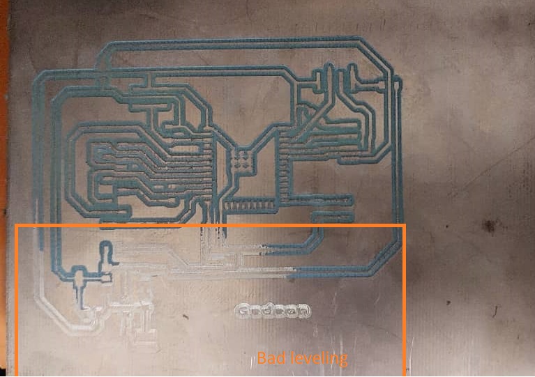
the machine bed is not well leveled This was the reason for the errrors encountered above.
The result of the mill without leveling properily
SO THIS IS WHAT I DID
Cleaned the machine's based
Layed the taped board starting from the inner center of the machine bed.
Leveled z for the new way. The side tape is to hold the board down.
I made the board and cut it out.
After soldering this is what i did
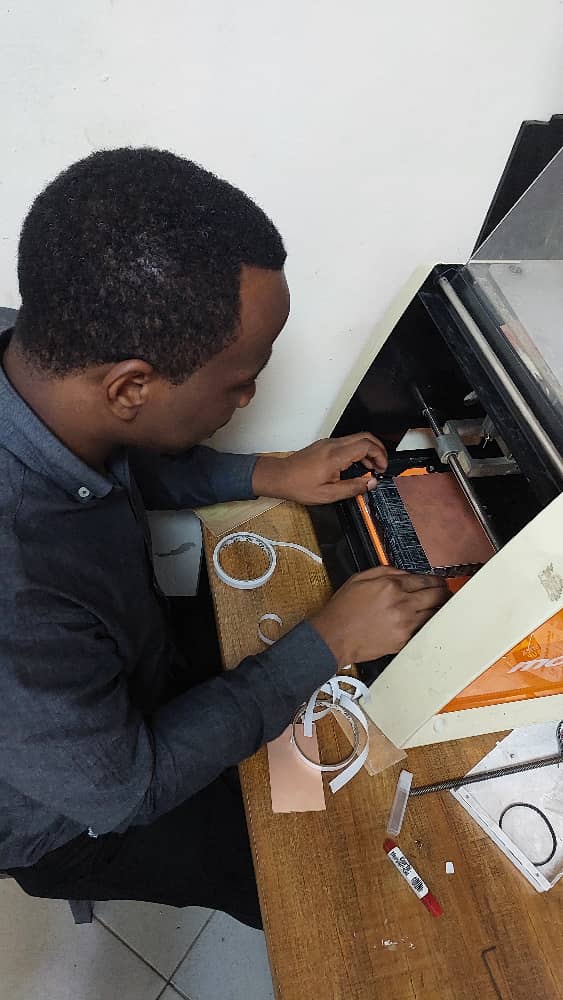
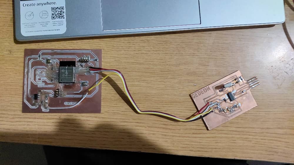
I connected the board to the programmer i build before
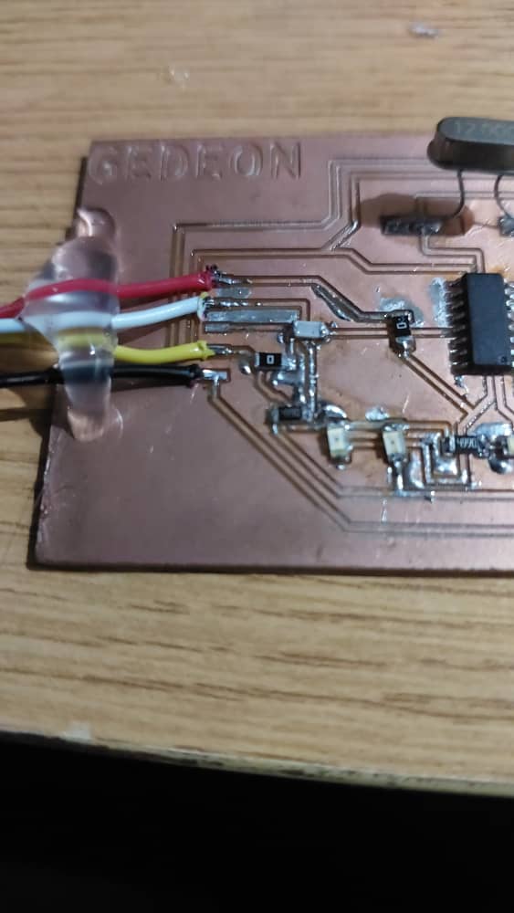
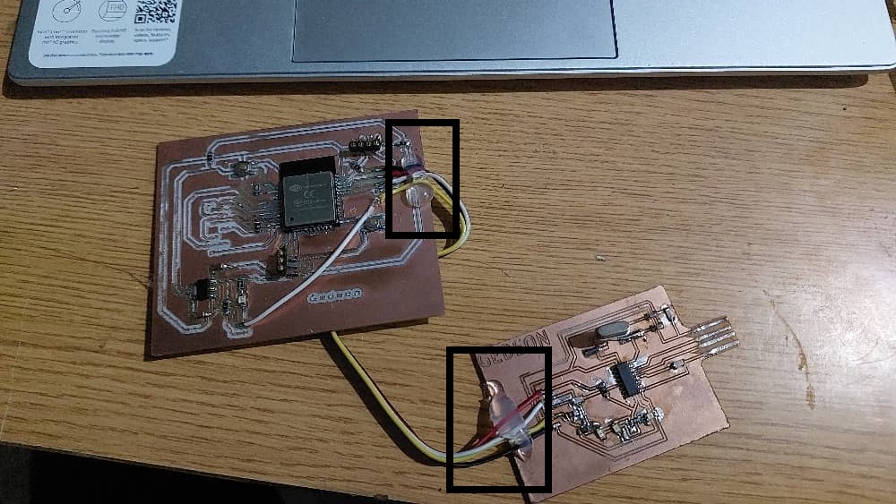
I chose immediate wire connection since the header pins usually get uprooted from the board when we keep using them
I had to glue the wires to the board to make sure they are fixed. This will help avoid the issues that may result from moving the boards multiple times
I plan to use the same board for other weeks' assignments since they are microcontroller based.
After that, a series of troubleshooting has to be done to avoid the fact that there could be a short-circuit
Then we connect to the computer
after connection
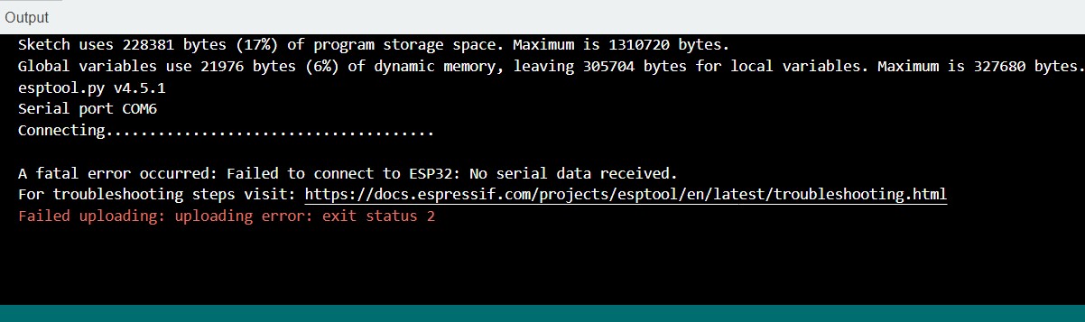
That looks like the UART is working but when we tried to load in the code, there was an error.
the error i keep on finding is like:
After trying many things here is the other error i keep getting
Arduino: 1.8.18 (Windows 10), Board: "ESP32 Dev Module, Disabled, Disabled, Default 4MB with spiffs (1.2MB APP/1.5MB SPIFFS), 240MHz (WiFi/BT), QIO, 80MHz, 4MB (32Mb), 921600, Core 1, Core 1, None, Disabled"
exec: "/bin/xtensa-esp32-elf-g++": file does not exist
Error compiling for board ESP32 Dev Module.
This report would have more information with
"Show verbose output during compilation"
option enabled in File -> Preferences.to remove this error, i had to follow these steps:
1. go to appdata->Arduino->delete
2. open arduino afresh, install esp32 library like before by copying the link from esspressif and installing
3. I made sure that all libraries refered to in the program were added to the local folder before running it.
After i can program the contoller, i will add in the program that runs an audio file then hear the outout from the speakers
the connection to the speakers will be like:
the program i plan to use is like:
#include "AudioGeneratorAAC.h"
#include "AudioOutputI2S.h"
#include "AudioFileSourcePROGMEM.h"
#include "sampleaac.h"
#define Bit_Clock_BCLK 27
#define Word_Select_WS 26
#define Serial_Data_SD 25
#define GAIN 0.125
AudioFileSourcePROGMEM *in;
AudioGeneratorAAC *aac;
AudioOutputI2S *out;
void setup(){
Serial.begin(115200);
in = new AudioFileSourcePROGMEM(sampleaac, sizeof(sampleaac));
aac = new AudioGeneratorAAC();
out = new AudioOutputI2S();
out -> SetGain(GAIN);
out -> SetPinout(Bit_Clock_BCLK,Word_Select_WS,Serial_Data_SD);
aac->begin(in, out);
}
void loop(){
if (aac->isRunning()) {
aac->loop();
} else {
aac -> stop();
Serial.printf("Sound Generator\n");
delay(1000);
}
}
The above program will help listen to the nokia tone repeatedely.
For now i look forward to having a working board.
Back again,
Since i could not find the MAX98357A PCM digital audio interface on the local market,
I opted to go with TDA2030A analog audio amplifier.
Not available
available
So chose to use the available components.
This is when you hear the audio file being played by the sp32
Since the audio from that file, was not that audible, i used a program that generates a simple tone.
It is a frequency based tone. i can change the tone by adjusting the frequency.
with the pogram i used you can change the tone and hear a different output.
Again it is possible to see the output through the serial Monitor
Hence an audio output was demonstrated.
I was able to load in a program that reads from a live stream of an online radio.
Many things are possible.
You only have to have matching libraries to the program one is using.
Forexample, the I2S audio library is needed in case the protocol is I2S. In the case of sp32 this is important.
Because of the final project i was able to mill a better PCB board to house an ESP32 and an audio amplifier along with a loud speaker
 The PCB is like:
 As you can see there are many 0 ohm resistors to try and avoid short circuits since there was manual routing of traces.
Having to use only one side of the board makes it very tricky of a job.
Using mods, i generated files for the SRM 20 milling machine.
As you can see there are many 0 ohm resistors to try and avoid short circuits since there was manual routing of traces.
Having to use only one side of the board makes it very tricky of a job.
Using mods, i generated files for the SRM 20 milling machine.
 I repaeted the process but now i used a different tool for the edge cuts.
However, since the lab has no 0.1mm bits i was obligated to use 0.2 and with it is hard to get clear lines.
Here is how the board looked like when i started soldering:
I repaeted the process but now i used a different tool for the edge cuts.
However, since the lab has no 0.1mm bits i was obligated to use 0.2 and with it is hard to get clear lines.
Here is how the board looked like when i started soldering:
 The parts that i marked with letters are the traces i had to use a wire to re-do.
That seemed tedious but i enjoyed not wasting a whole board, so i found another way.
I used a multimeter to test if there are any unwanted conncetions.
I found the board fine, it will work.
As i progress soldering:
The parts that i marked with letters are the traces i had to use a wire to re-do.
That seemed tedious but i enjoyed not wasting a whole board, so i found another way.
I used a multimeter to test if there are any unwanted conncetions.
I found the board fine, it will work.
As i progress soldering:
 There remains an ESP 32 controller to be soldered on. I will add it in when i get it, since we currently are low on that stock.
In the meantime, I found out that the traces are coming off
There remains an ESP 32 controller to be soldered on. I will add it in when i get it, since we currently are low on that stock.
In the meantime, I found out that the traces are coming off
 Despite the fact that the board also looked bad, un clean in a sort, I decided to print the same circuit again.
Things i changed:
Despite the fact that the board also looked bad, un clean in a sort, I decided to print the same circuit again.
Things i changed:
 the machine bed is not well leveled This was the reason for the errrors encountered above.
The result of the mill without leveling properily
the machine bed is not well leveled This was the reason for the errrors encountered above.
The result of the mill without leveling properily
 SO THIS IS WHAT I DID
 I connected the board to the programmer i build before
I chose immediate wire connection since the header pins usually get uprooted from the board when we keep using them
I connected the board to the programmer i build before
I chose immediate wire connection since the header pins usually get uprooted from the board when we keep using them
 I had to glue the wires to the board to make sure they are fixed. This will help avoid the issues that may result from moving the boards multiple times
I plan to use the same board for other weeks' assignments since they are microcontroller based.
I had to glue the wires to the board to make sure they are fixed. This will help avoid the issues that may result from moving the boards multiple times
I plan to use the same board for other weeks' assignments since they are microcontroller based.
 After that, a series of troubleshooting has to be done to avoid the fact that there could be a short-circuit
Then we connect to the computer
After that, a series of troubleshooting has to be done to avoid the fact that there could be a short-circuit
Then we connect to the computer
 after connection
 That looks like the UART is working but when we tried to load in the code, there was an error.
the error i keep on finding is like:
That looks like the UART is working but when we tried to load in the code, there was an error.
the error i keep on finding is like:
 After trying many things here is the other error i keep getting
Arduino: 1.8.18 (Windows 10), Board: "ESP32 Dev Module, Disabled, Disabled, Default 4MB with spiffs (1.2MB APP/1.5MB SPIFFS), 240MHz (WiFi/BT), QIO, 80MHz, 4MB (32Mb), 921600, Core 1, Core 1, None, Disabled"
exec: "/bin/xtensa-esp32-elf-g++": file does not exist
Error compiling for board ESP32 Dev Module.
This report would have more information with
"Show verbose output during compilation"
option enabled in File -> Preferences.
to remove this error, i had to follow these steps:
1. go to appdata->Arduino->delete
2. open arduino afresh, install esp32 library like before by copying the link from esspressif and installing
3. I made sure that all libraries refered to in the program were added to the local folder before running it.
After i can program the contoller, i will add in the program that runs an audio file then hear the outout from the speakers
the connection to the speakers will be like:
After trying many things here is the other error i keep getting
Arduino: 1.8.18 (Windows 10), Board: "ESP32 Dev Module, Disabled, Disabled, Default 4MB with spiffs (1.2MB APP/1.5MB SPIFFS), 240MHz (WiFi/BT), QIO, 80MHz, 4MB (32Mb), 921600, Core 1, Core 1, None, Disabled"
exec: "/bin/xtensa-esp32-elf-g++": file does not exist
Error compiling for board ESP32 Dev Module.
This report would have more information with
"Show verbose output during compilation"
option enabled in File -> Preferences.
to remove this error, i had to follow these steps:
1. go to appdata->Arduino->delete
2. open arduino afresh, install esp32 library like before by copying the link from esspressif and installing
3. I made sure that all libraries refered to in the program were added to the local folder before running it.
After i can program the contoller, i will add in the program that runs an audio file then hear the outout from the speakers
the connection to the speakers will be like:
 the program i plan to use is like:
#include "AudioGeneratorAAC.h"
#include "AudioOutputI2S.h"
#include "AudioFileSourcePROGMEM.h"
#include "sampleaac.h"
#define Bit_Clock_BCLK 27
#define Word_Select_WS 26
#define Serial_Data_SD 25
#define GAIN 0.125
AudioFileSourcePROGMEM *in;
AudioGeneratorAAC *aac;
AudioOutputI2S *out;
void setup(){
Serial.begin(115200);
in = new AudioFileSourcePROGMEM(sampleaac, sizeof(sampleaac));
aac = new AudioGeneratorAAC();
out = new AudioOutputI2S();
out -> SetGain(GAIN);
out -> SetPinout(Bit_Clock_BCLK,Word_Select_WS,Serial_Data_SD);
aac->begin(in, out);
}
void loop(){
if (aac->isRunning()) {
aac->loop();
} else {
aac -> stop();
Serial.printf("Sound Generator\n");
delay(1000);
}
}
The above program will help listen to the nokia tone repeatedely.
For now i look forward to having a working board.
Back again,
Since i could not find the MAX98357A PCM digital audio interface on the local market,
I opted to go with TDA2030A analog audio amplifier.
the program i plan to use is like:
#include "AudioGeneratorAAC.h"
#include "AudioOutputI2S.h"
#include "AudioFileSourcePROGMEM.h"
#include "sampleaac.h"
#define Bit_Clock_BCLK 27
#define Word_Select_WS 26
#define Serial_Data_SD 25
#define GAIN 0.125
AudioFileSourcePROGMEM *in;
AudioGeneratorAAC *aac;
AudioOutputI2S *out;
void setup(){
Serial.begin(115200);
in = new AudioFileSourcePROGMEM(sampleaac, sizeof(sampleaac));
aac = new AudioGeneratorAAC();
out = new AudioOutputI2S();
out -> SetGain(GAIN);
out -> SetPinout(Bit_Clock_BCLK,Word_Select_WS,Serial_Data_SD);
aac->begin(in, out);
}
void loop(){
if (aac->isRunning()) {
aac->loop();
} else {
aac -> stop();
Serial.printf("Sound Generator\n");
delay(1000);
}
}
The above program will help listen to the nokia tone repeatedely.
For now i look forward to having a working board.
Back again,
Since i could not find the MAX98357A PCM digital audio interface on the local market,
I opted to go with TDA2030A analog audio amplifier.
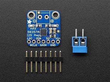 Not available
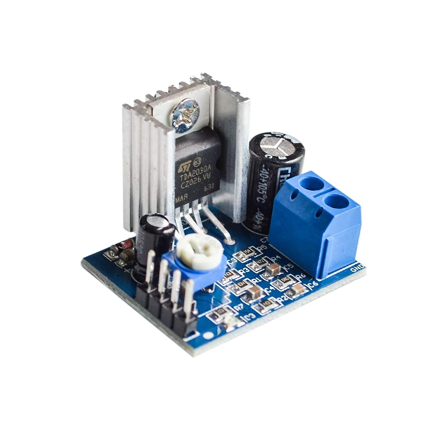 available
So chose to use the available components.
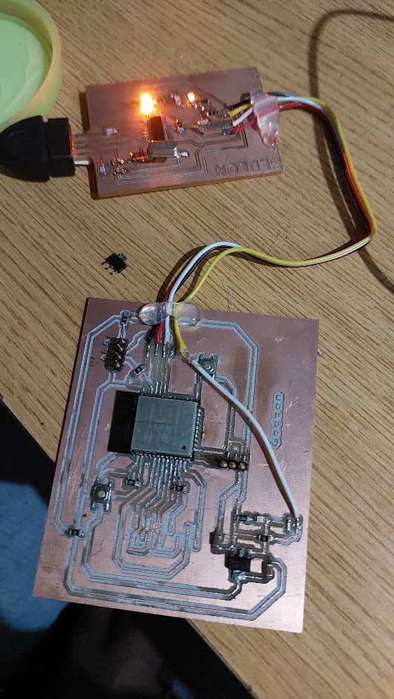
This is when you hear the audio file being played by the sp32
Since the audio from that file, was not that audible, i used a program that generates a simple tone.
It is a frequency based tone. i can change the tone by adjusting the frequency.
with the pogram i used you can change the tone and hear a different output.
Again it is possible to see the output through the serial Monitor
Hence an audio output was demonstrated.
I was able to load in a program that reads from a live stream of an online radio.
Many things are possible.
You only have to have matching libraries to the program one is using.
Forexample, the I2S audio library is needed in case the protocol is I2S. In the case of sp32 this is important.
Because of the final project i was able to mill a better PCB board to house an ESP32 and an audio amplifier along with a loud speaker
available
So chose to use the available components.
This is when you hear the audio file being played by the sp32
Since the audio from that file, was not that audible, i used a program that generates a simple tone.
It is a frequency based tone. i can change the tone by adjusting the frequency.
with the pogram i used you can change the tone and hear a different output.
Again it is possible to see the output through the serial Monitor
Hence an audio output was demonstrated.
I was able to load in a program that reads from a live stream of an online radio.
Many things are possible.
You only have to have matching libraries to the program one is using.
Forexample, the I2S audio library is needed in case the protocol is I2S. In the case of sp32 this is important.
Because of the final project i was able to mill a better PCB board to house an ESP32 and an audio amplifier along with a loud speaker
