This week's assignment is like:
group assignment
do your lab's safety training
test runout, alignment, fixturing, speeds, feeds, materials, and toolpaths for your machine
individual assignment
make (design+mill+assemble) something big (~meter-scale)
extra credit: don't use fasteners or glue
extra credit: include curved surfaces
Group assignment:
Safety
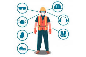
Ideally we should be talking about: Use of PPE (Personal Protective Equipment)
Overall
Gloves
Safety boots
Nozzle mask
However, given the lab's conditions, this seems like a privilage for now.
I used to teach a class to TVET students dealing with Fiber optics. Here is some of the things I'd tell them in safety:
COFFEE
One of the best ways to work safely at anything is by having an easily remembered procedure for dealing with the task and one of the neatest we have heard of is the COFFEE quick reference. This "acronym" is used as a quick reference and stands for the following :
C : Chemical Hazards.
Store chemicals safely and correctly labeled.
Use chemicals in well ventilated area.
Keep chemicals away from your skin and eyes and avoid ingestion.
Be familiar with COSHH (Care Of Substances Hazardous to Health) guidelines.
O : Optical Hazards.
FF : fibre Fragments Hazards.
Dispose of all fibre fragments in a suitable container.
Keep ends of fibres away from eyes, skin and clothing.
Don't pick up fibre fragments by hand, use sticky tape for example.
E : Environmental Hazards.
Be aware of potential hazards in your working space.
Consider how your working space will affect you and your equipment.
E : Everyone.
Explain any safety issues to other people in your working space or working with you.
Respect the safety of others around you.
When appropriate erect warning signs or even barriers.

 Testing
- runout:
I don't think our lab has a cylindrical runout testing tool for the spindle.
However, if the milling bit wears out the recommendation is to replace it or before each job,calculate the diameter and adjust it in the toolpath creation.
- alignment:
Our machine has been leveled and aligned.
I don't know how to align but I keep the belts and runways of the machine greesed and oiled.
- fixturing:
Proper clamping and fixturing ensures the material stays inplace,while the job is being done.
I use either Clamps or drills in the sacrifical material.
- speeds:
Lower the speed if working with hard surfaces. Otherwise, the tool will break.
- feeds:
Feed rate means how fast the CNC os running to take the next line.
It's better to have it at a low rate like 15% or 30% depenting on the material.
- materials:
Wood (MDF, Plywood, cherry, mapple,OBS...) Metal (aluminum thin layers) Plastic.
- toolpaths for our machine
Pocket profile drill 3d rough, smooth Vcarve and mamy others.
However, the lab's group assignment is linked here
INDIVIDUAL ASSIGNMENT
Since i was working from another lab on Friday, and this lab had no proper materials to use for this big assignment,
I tried to cut a leaf cadre for the decorative usage.
Machine specifications:
Brand: BlueElephant
Model: ELECNC6090
Bed size: 60cmx90cm
Image source is: https://3axis.co/free-vector/
Editing software: Vertic ASpire 9.0
CAM software: Mach3 mill
Material used: 3mm MDF 67cmx57cm
Tool: 3mm ballnose milling bit
toolpaths: 3mm deep profile with 1mm offset, climb mode, automatic vector selection,with 20mm machine jog clearance.
Toolpath format: .mmg
Clamping mode: Bed edge ties
Outcome:
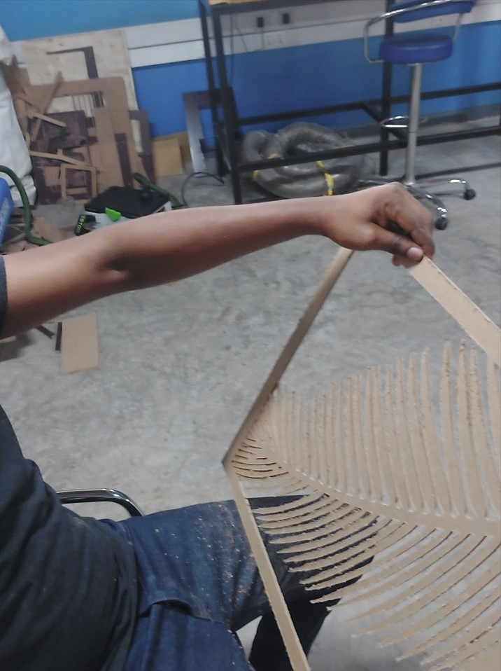 As you may see, some parts broke because there was no fixture in the middle and vibrations got high.
The material tended to pop-out as the tool would pass somewhere a bit far from the fixtures.
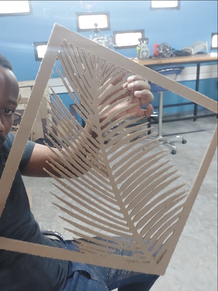 That is how the material looked before cleaning.
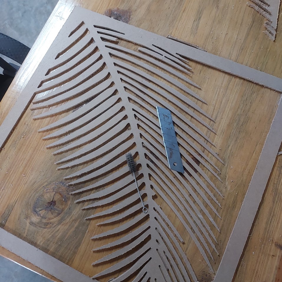 After i tried to clean the material,...
Back to the individual assignment!!
Goal: To design, mill and asssemble something big
The idea is to cut parts that fits together with eachother.
I used two types of joints t-bone and rectagular fits.
Using solidworks following are the steps i followed:
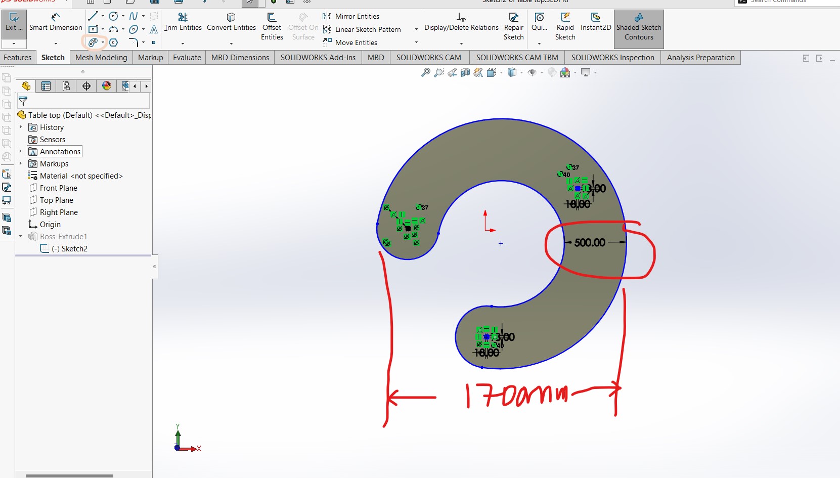
step1: Sketch the top
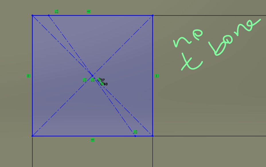
 What I call T-Bone joint, is just a rectangle of 18x18 with 4 circles of 2mm radius on each edge.
I used the trim tool to make it one contour/surface.
 The other joint is uset in the middle of the table just so i will be able to see the difference.
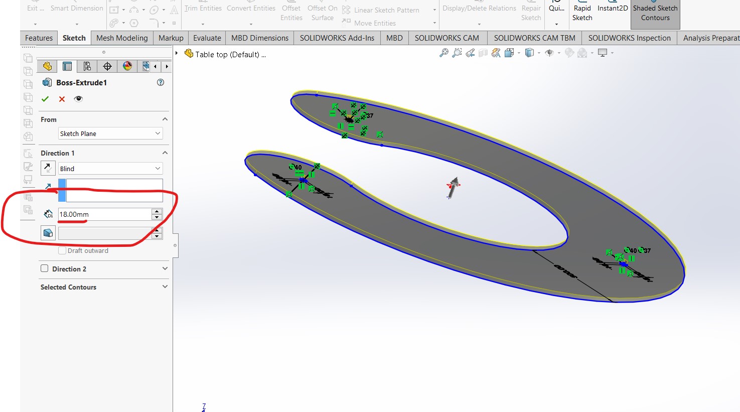
 Then i extruded bross to the thickness of the material that i will be using: an MDF 18mm
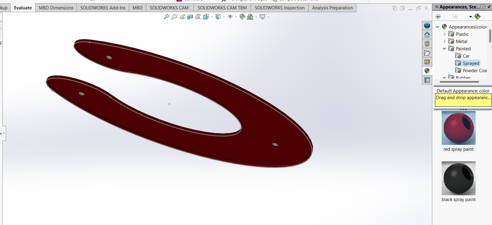
 I proceeded to changing the color for appearance:
 Setp 2: Sketch the leg
Similar process:i thought the base should be big enough but not too big in comparision to the table top cross area (which has a distance of 500mm).
Hence i gave the leg base of 400mm. Going up I triede to reduce the widthby half.
The tip of the leg, which is going to be connected to the top as a joint has also dimensions reflecting the thichness of the material almost 18x18 mm.
I gave it a little torelance of 1.5 mm so it can fit.
 I also extruded to the thickness of the material: 18mm
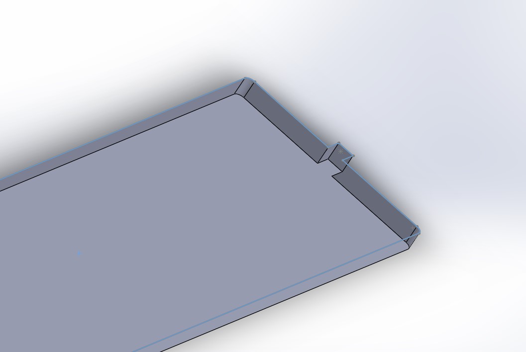 Step 3:Assembling
I tried to assemble both parts (for the first time doing my own unsupervised assembly)
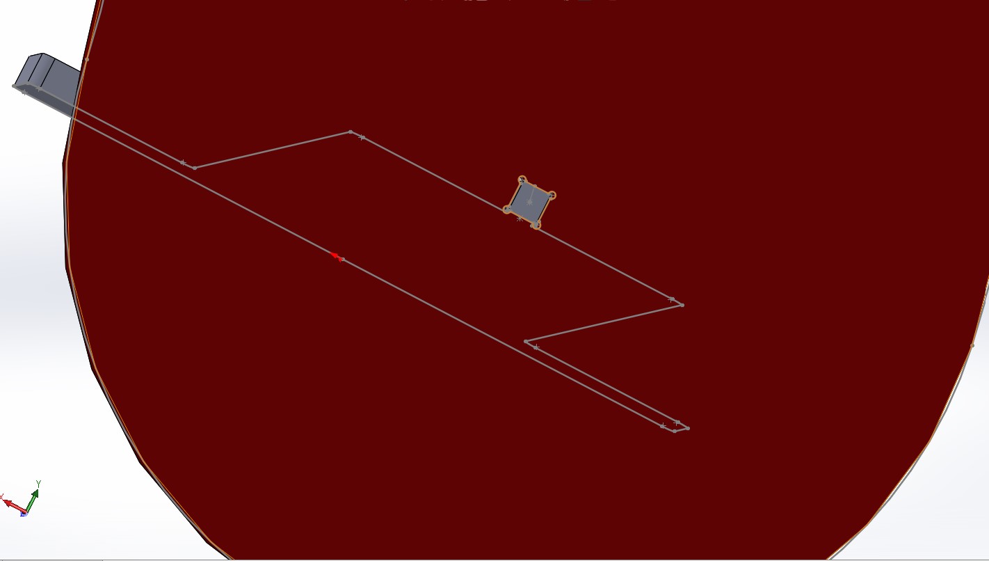 this is another view :
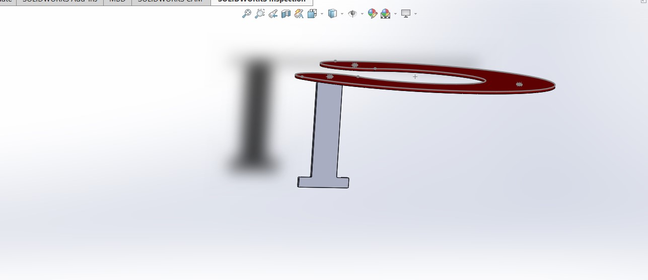
 And the hero shoot of the morning (PS: i did this early in the morning at home) is:
 Step 4: Exporting (saving as) DXF files:
The top:
Select the part's original plane, Normal to it, click on "save as", choose the format of DXF
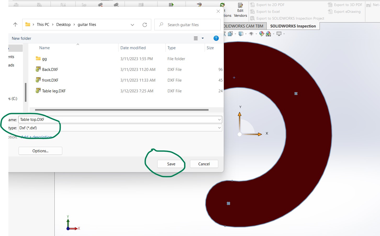 Follow the process
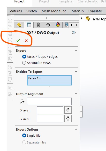 Until you save:
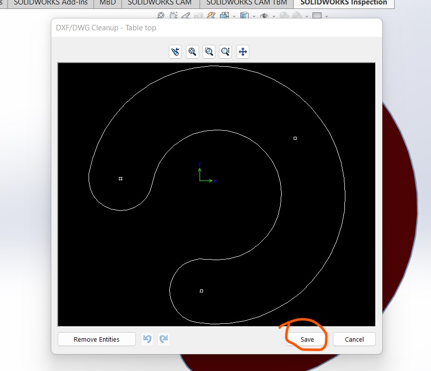 Do the same (above process) for the leg part as well:
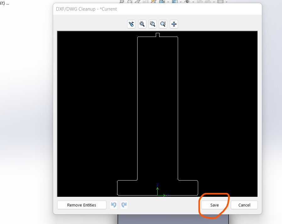 The idea is that i will cut 3 leg parts, identically, and join them to the top part.
Making the toolpaths for the Shopbot:
Step1: Open the Vcarve software and import the dxf file for the legs
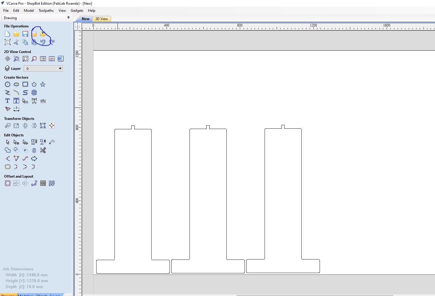 Step2: Make the toolpath for the Parts without changing the dimension:
I used the profile, through with 6 passes, a 6mm tool.
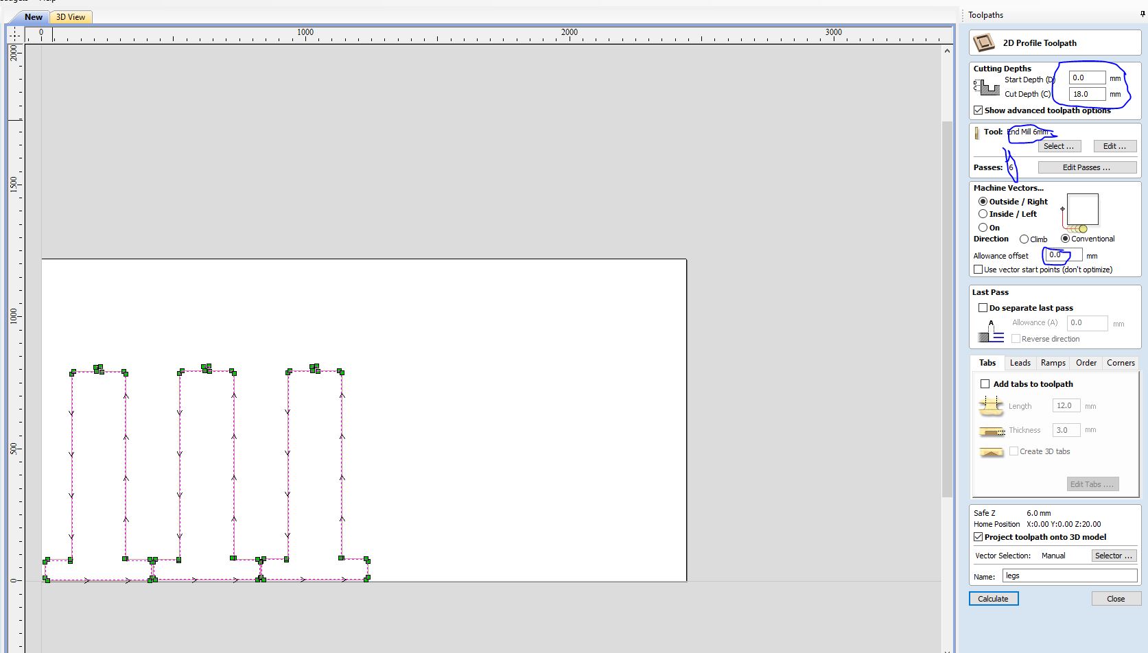 Step3: Save the toolpath and load it into the machine controller.
The format is the is .mmg
The machine controller is Shopbot
Step4: Import the top vectors (dxf) and repeat the same process as above
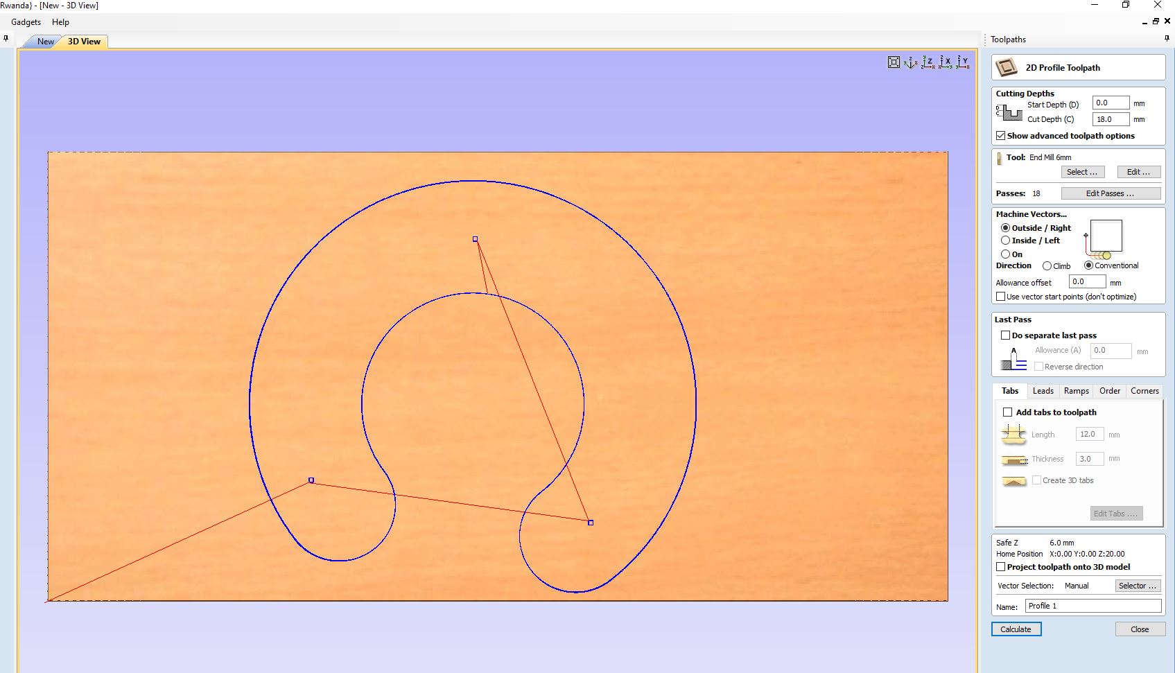 Step5: Simulate and see what the cut will be like.
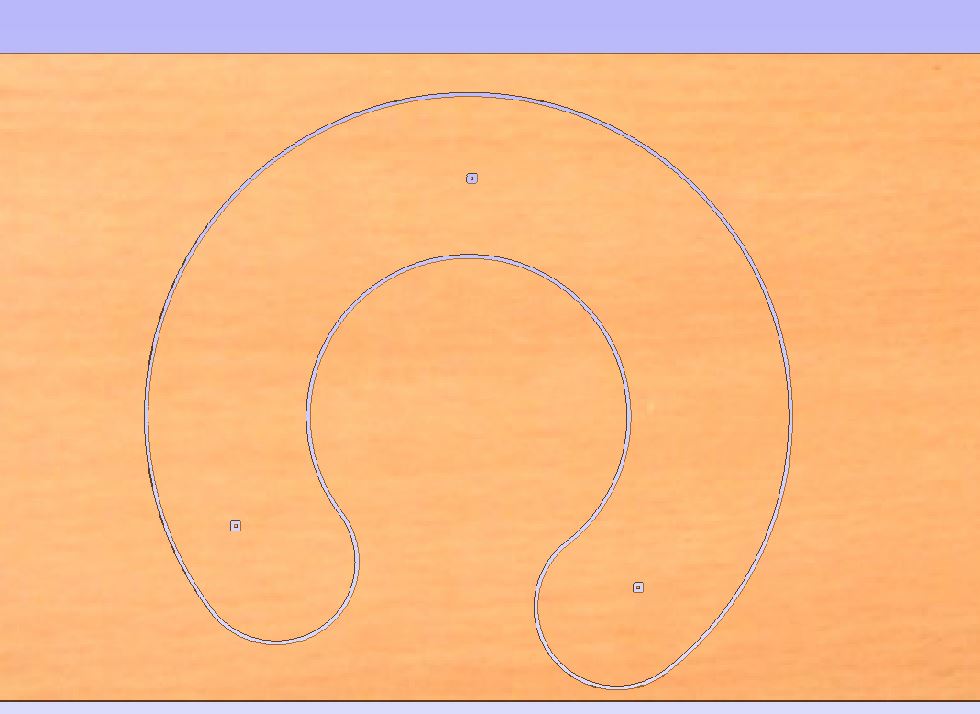 the cutting work
THe machine's stervo motor
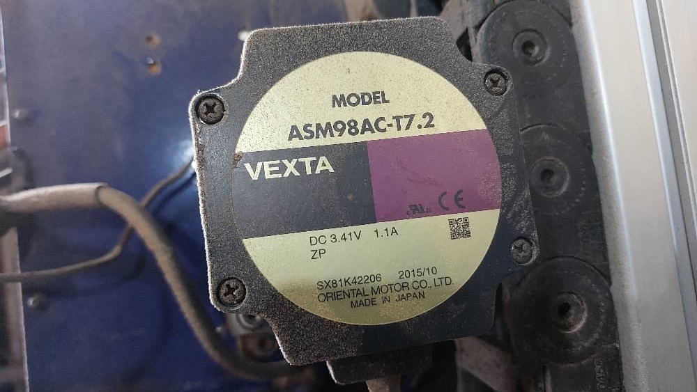 >> me fitting in the 6mm tool
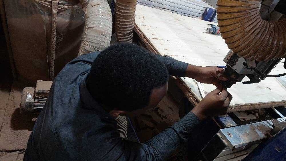 >> Holding the bit and tighten it with hands
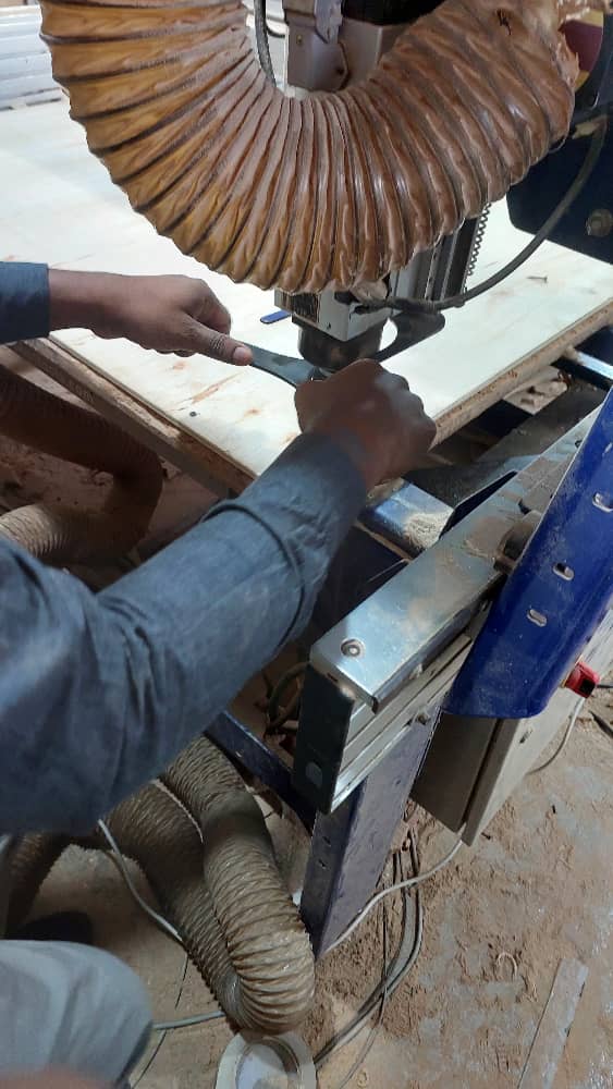
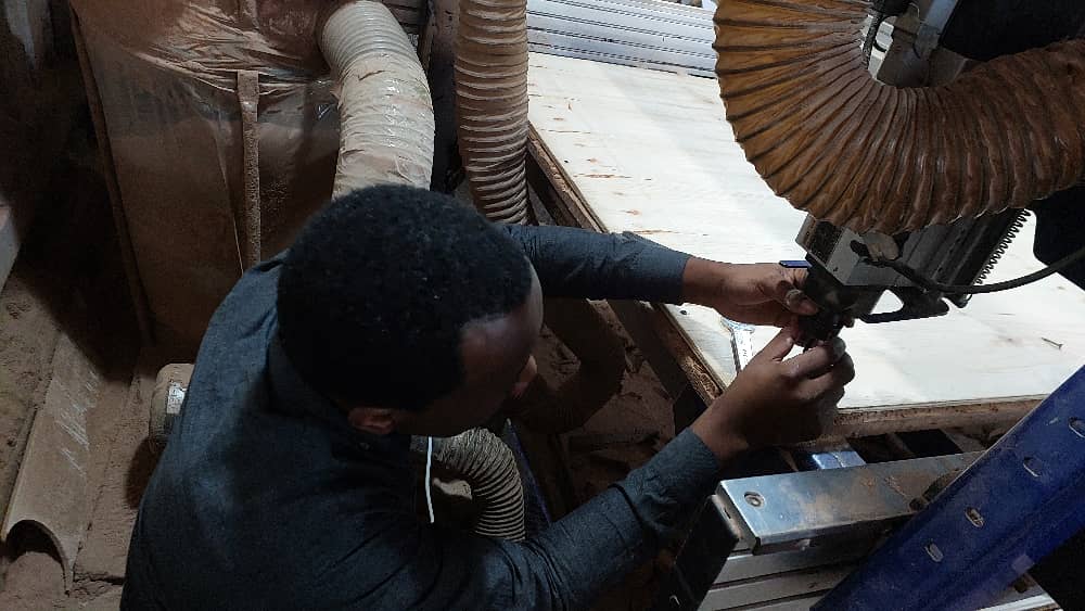 >> Tighten the tool with the spanners
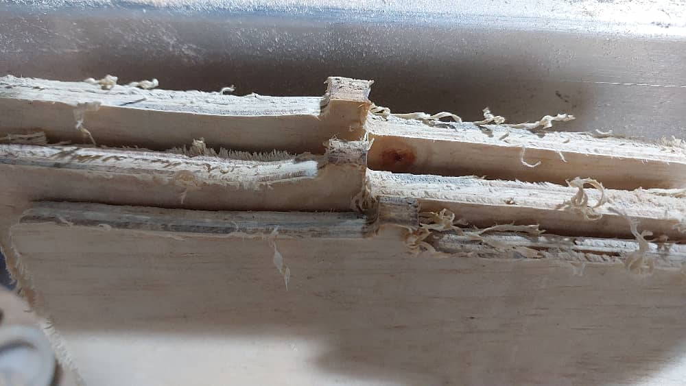
 >>Issues i had because the machine's bed is not well leveled. The trace wasn't eating up same amount of material
 >> Finally the piece came out
 >> The joint is not as expected but the with a few trims we can
 >>These are the parts before i assembled
 >> this is how i wish the assembled work shouls be! Obviously it won't
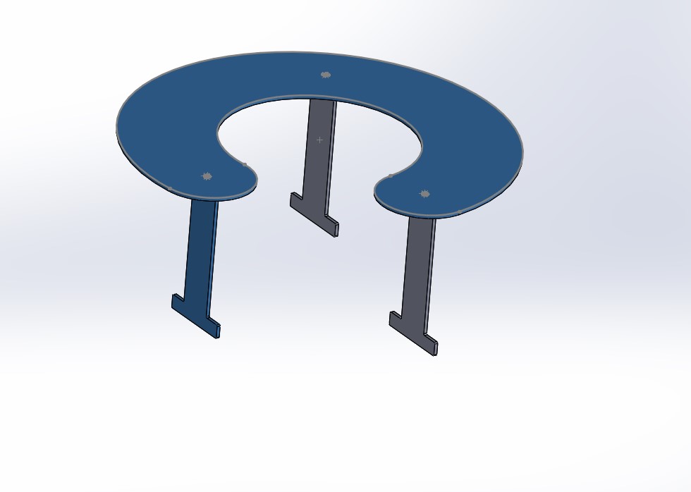 Reality
sanding the rough edges ans the chamfs i had to clean. Plus there was an error on the joints:
I had reduced the size from 18 to 9 in vcarver (because we had no 18mm mdf), then on one side i clicked join close vectors.
The software gave me curved angles instead of straight ones.
I used a table saw to rectify that.
>> After sanding, i joined:
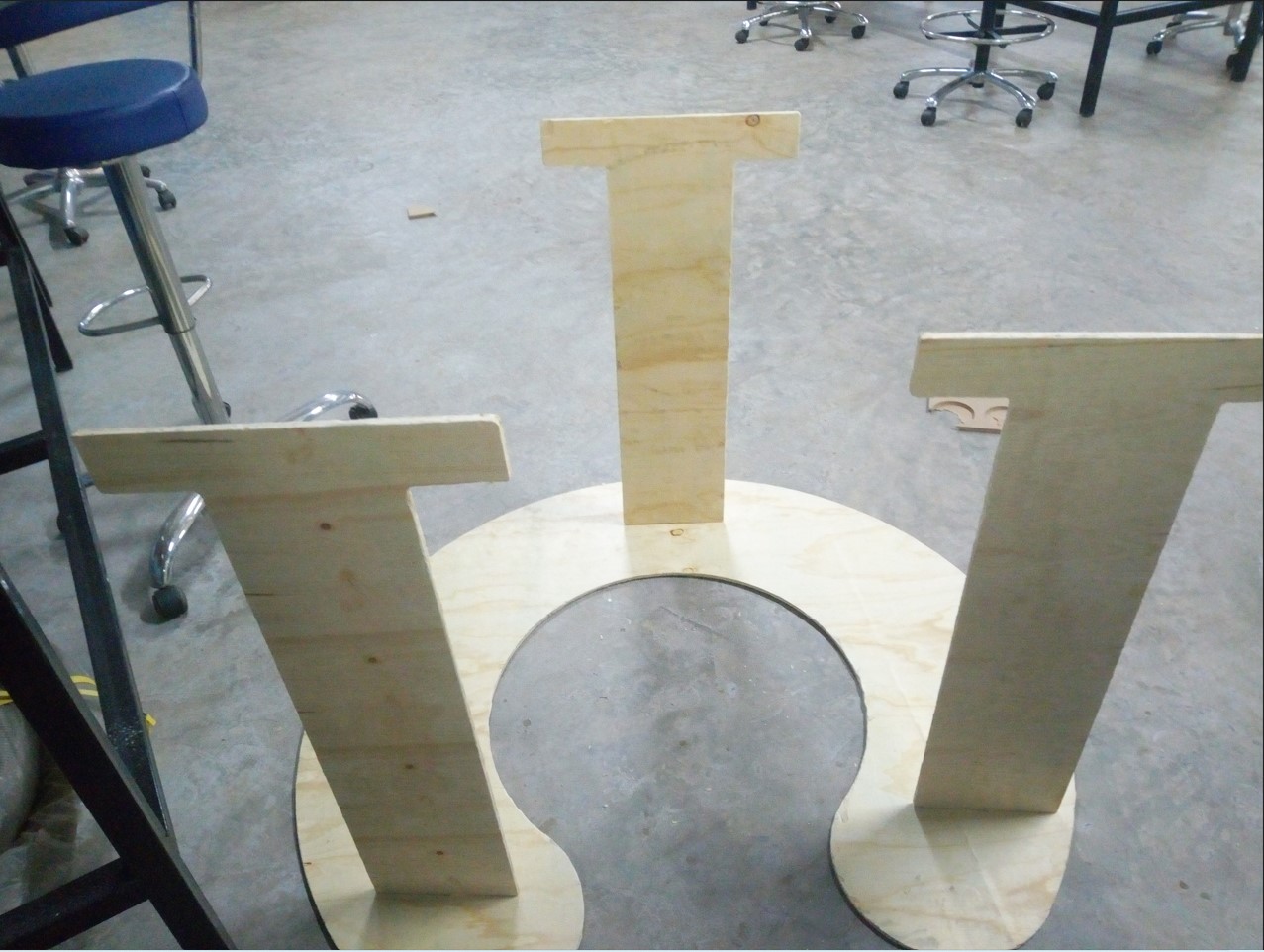 >> it looked promising before i flip it up!
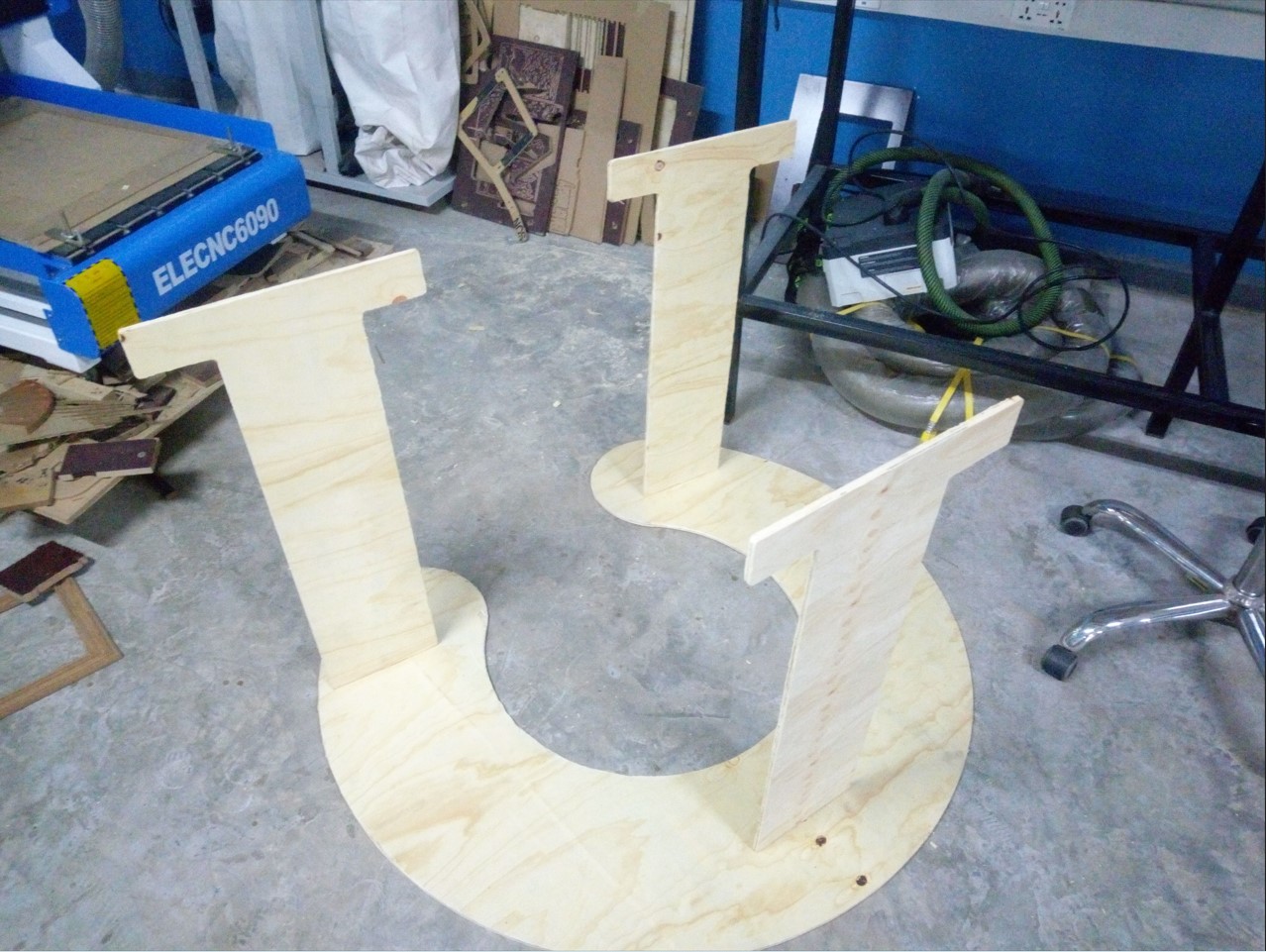 >>Then i flip it up but it could not stand by its own.
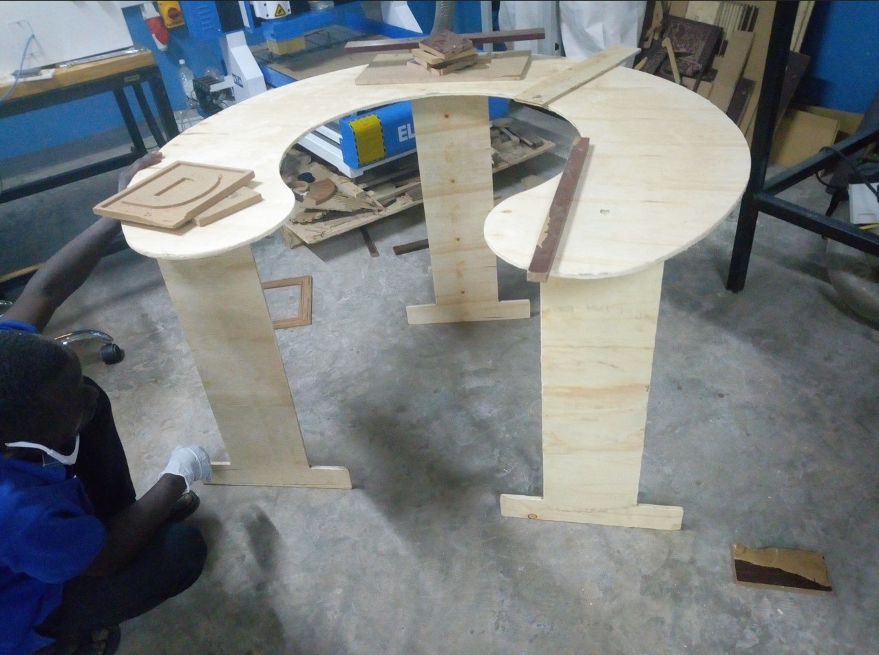 >> I think the surfafe base was not strong enough to allow full equilibrium
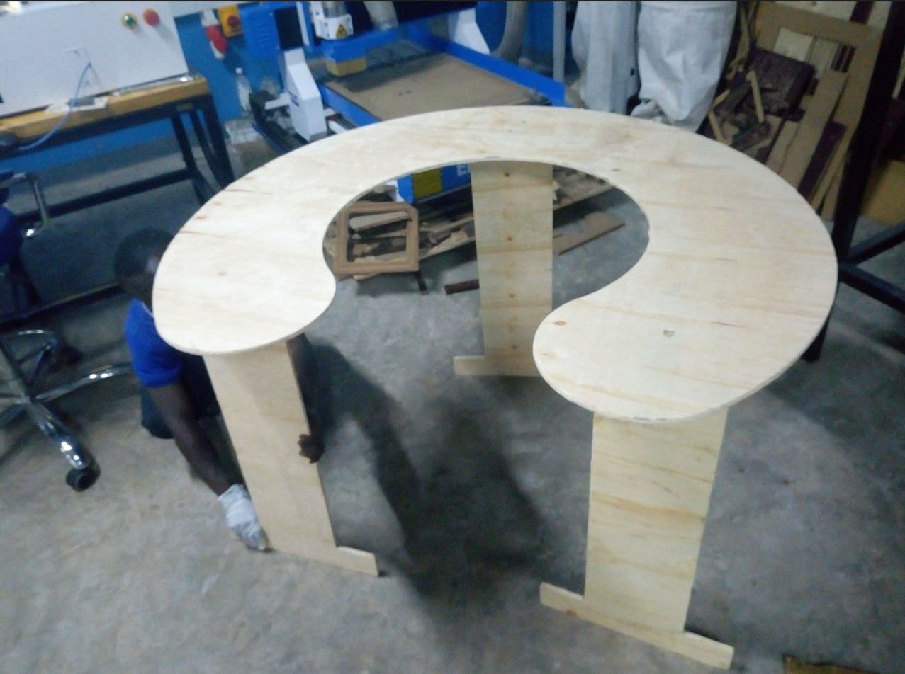 >> As a solution i cut the legs in another way, making a + intersection
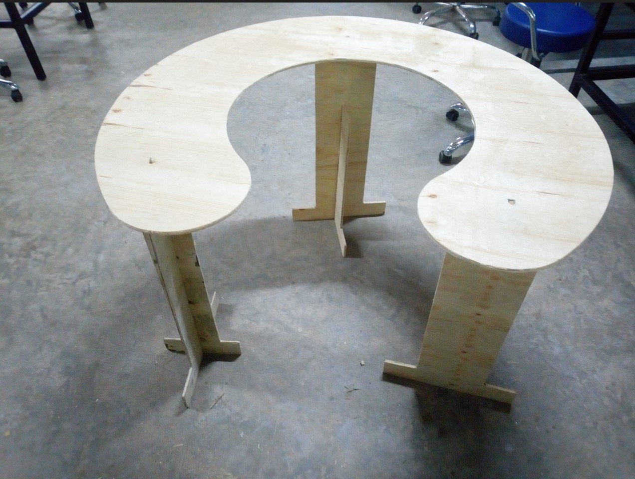
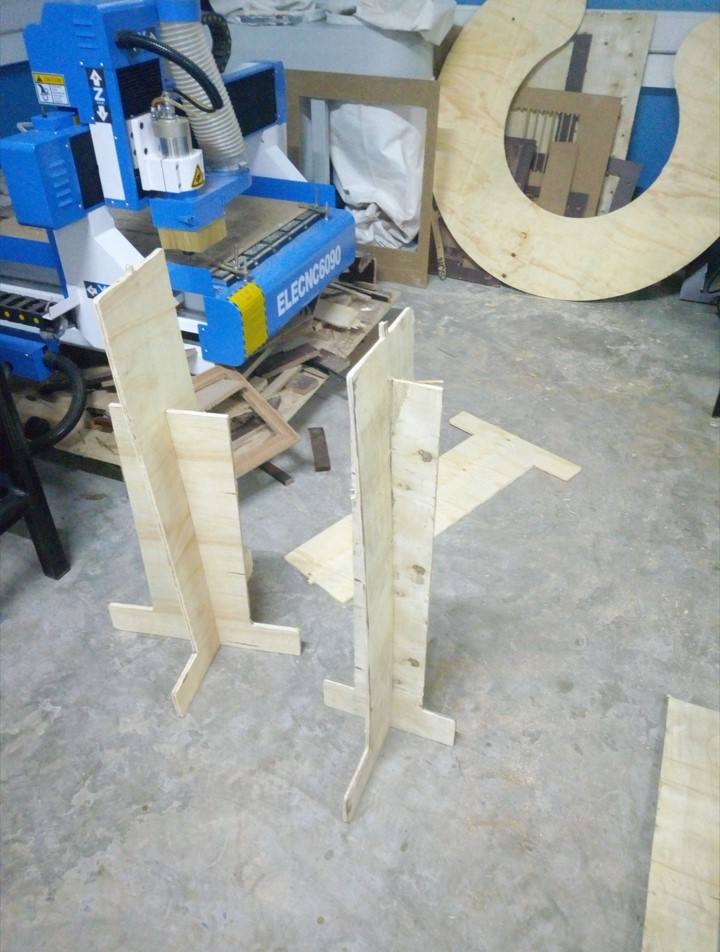 >> Then it worked out just fine.
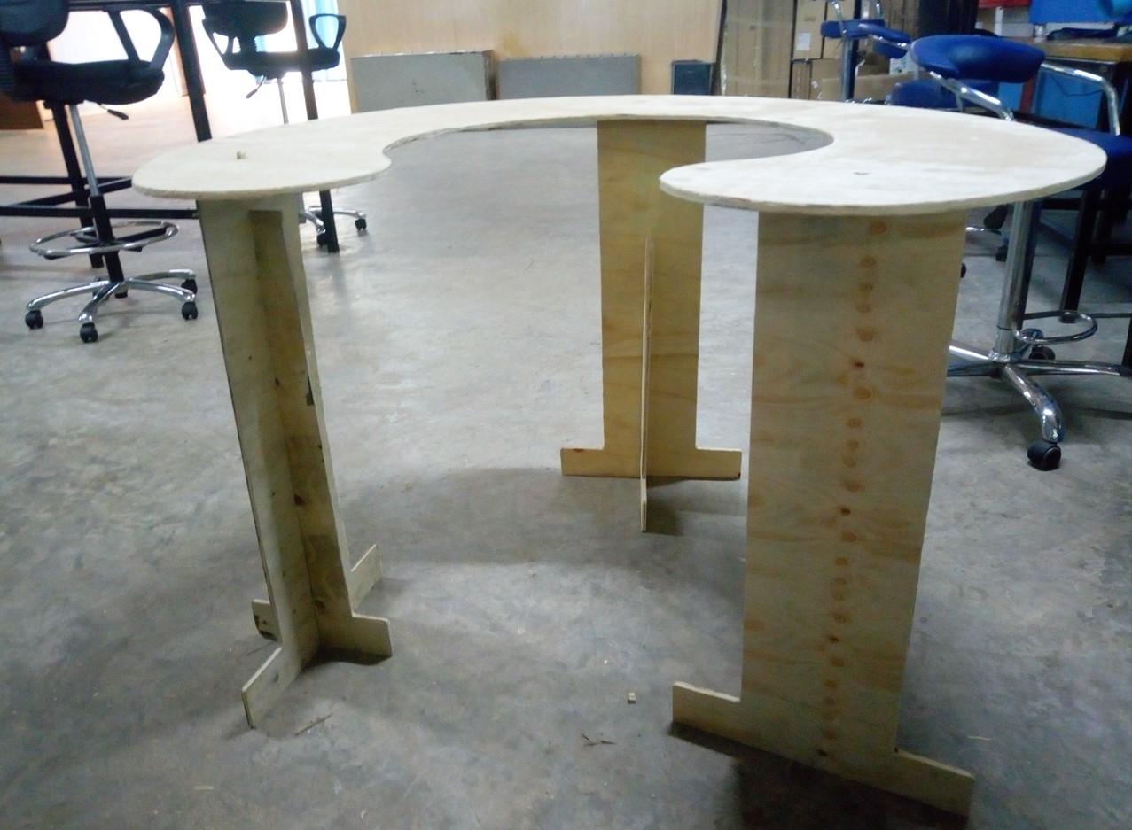 >> you can see that it stands

 Testing
 As you may see, some parts broke because there was no fixture in the middle and vibrations got high.
The material tended to pop-out as the tool would pass somewhere a bit far from the fixtures.
 That is how the material looked before cleaning.
 After i tried to clean the material,...

 The other joint is uset in the middle of the table just so i will be able to see the difference.
 Then i extruded bross to the thickness of the material that i will be using: an MDF 18mm
 I proceeded to changing the color for appearance:
 Setp 2: Sketch the leg
Similar process:i thought the base should be big enough but not too big in comparision to the table top cross area (which has a distance of 500mm).
Hence i gave the leg base of 400mm. Going up I triede to reduce the widthby half.
The tip of the leg, which is going to be connected to the top as a joint has also dimensions reflecting the thichness of the material almost 18x18 mm.
I gave it a little torelance of 1.5 mm so it can fit.
 I also extruded to the thickness of the material: 18mm
 Step 3:Assembling
I tried to assemble both parts (for the first time doing my own unsupervised assembly)
 this is another view :
 And the hero shoot of the morning (PS: i did this early in the morning at home) is:
 Step 4: Exporting (saving as) DXF files:
The top:
Select the part's original plane, Normal to it, click on "save as", choose the format of DXF
 Follow the process
 Until you save:
 Do the same (above process) for the leg part as well:
 The idea is that i will cut 3 leg parts, identically, and join them to the top part.
Making the toolpaths for the Shopbot:
Step1: Open the Vcarve software and import the dxf file for the legs
 Step2: Make the toolpath for the Parts without changing the dimension:
I used the profile, through with 6 passes, a 6mm tool.
 Step3: Save the toolpath and load it into the machine controller.
The format is the is .mmg
The machine controller is Shopbot
Step4: Import the top vectors (dxf) and repeat the same process as above
 Step5: Simulate and see what the cut will be like.
 the cutting work
THe machine's stervo motor
 >> me fitting in the 6mm tool
 >> Holding the bit and tighten it with hands
 >> Tighten the tool with the spanners
 >>Issues i had because the machine's bed is not well leveled. The trace wasn't eating up same amount of material
 >> Finally the piece came out
 >> The joint is not as expected but the with a few trims we can
 >>These are the parts before i assembled
 >> this is how i wish the assembled work shouls be! Obviously it won't
 Reality
sanding the rough edges ans the chamfs i had to clean. Plus there was an error on the joints:
I had reduced the size from 18 to 9 in vcarver (because we had no 18mm mdf), then on one side i clicked join close vectors.
The software gave me curved angles instead of straight ones.
I used a table saw to rectify that.
>> After sanding, i joined:
 >> it looked promising before i flip it up!
 >>Then i flip it up but it could not stand by its own.
 >> I think the surfafe base was not strong enough to allow full equilibrium
 >> As a solution i cut the legs in another way, making a + intersection
 >> Then it worked out just fine.
 >> you can see that it stands

