Plan for dissemination of my project:
1. finish the embedded system part by Monday the 29th of May
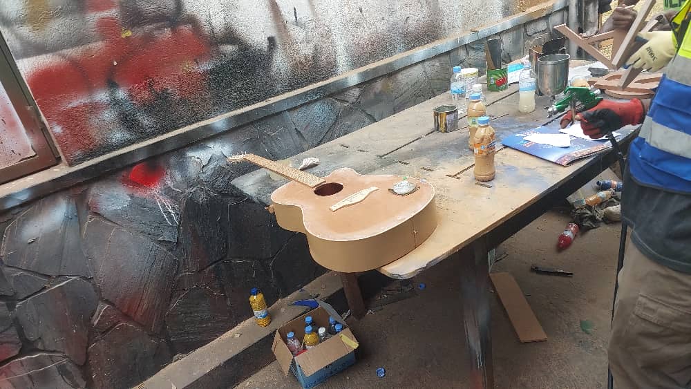
2. Buy wood and cut the guitar by Saturday the 3rd June
3. Assembly and testing by sunday the 4th June
4. Make a video for final presentation before the 6th of June
5. Document everything about my final project before the 7th of June.
So far i have started working on the electronics part
I also sent in the request for material from the fablab
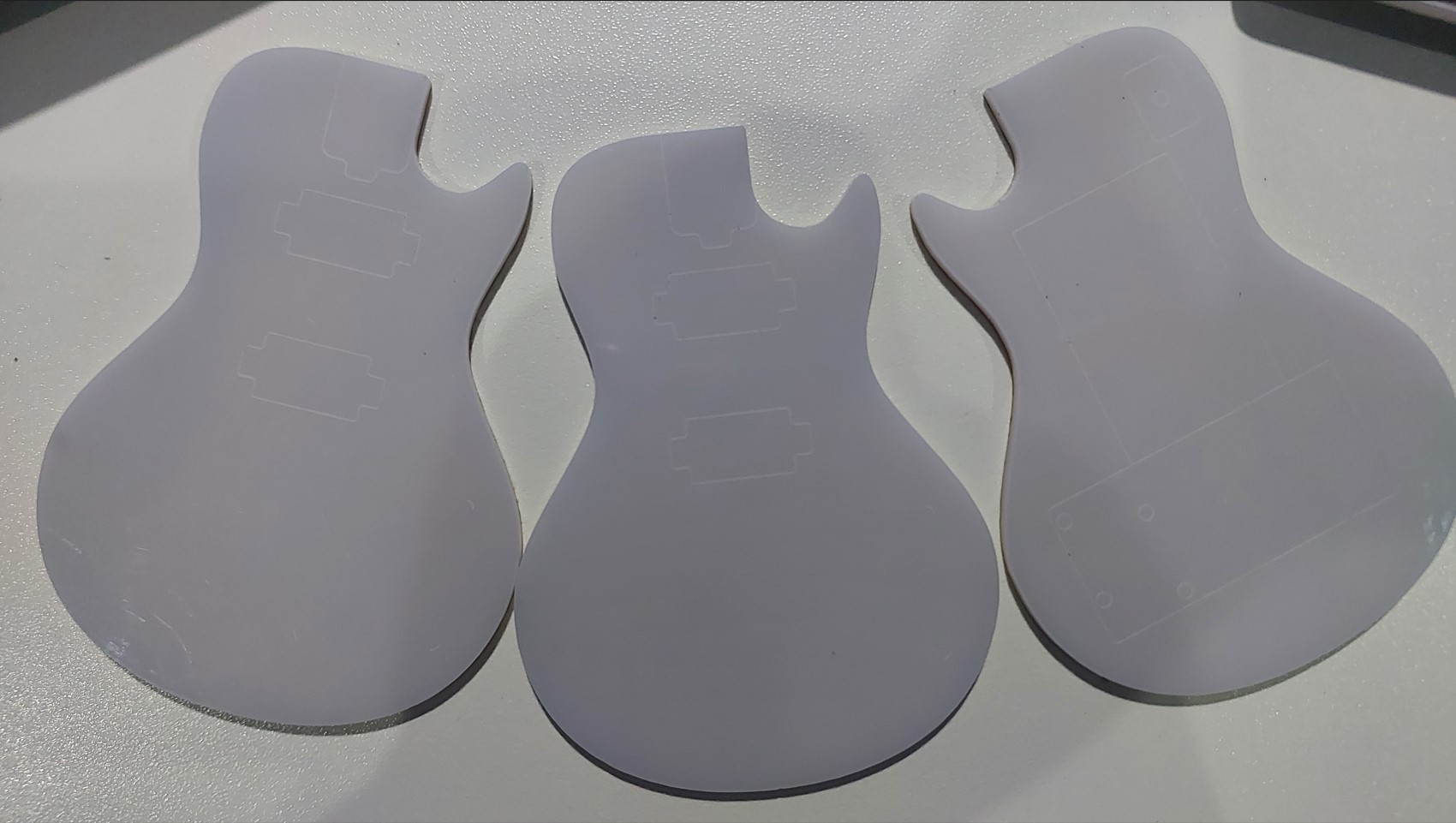
These are the shapes i cut on acrylic using a laser cutter to be able to visualize the project.
Thinking about my Summary slides
What will it do?
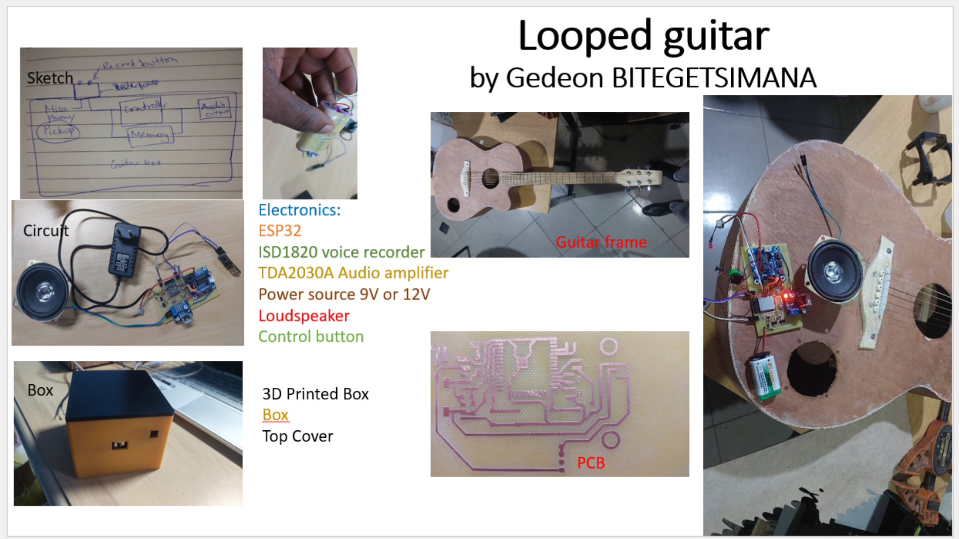
My proposed project is a guitar that has the capacity to record a piece of music and play it back on loop.
The user of the guitar may choose to play another live piece of music. Then it will sound like two pieces of music are playing at the same time.
Who's done what beforehand?
In the fab academy, I saw people who did the boom box, another one who did “Legos” for Sound
Physical Modular Sound Blocks for sound and music and many other projects.
However none of them resembled mine exactly.
On the market you may find guitar pedals with loops. However they are costly and it is a separate tool away from the guitar. MINE WILL BE INTEGRATED INSIDE A GUITAR.
What will you design?
1. I will design the electronic circuit for the whole process of recording, , playing back on a loop.
2. I will design the guitar frame: Acoustic version
3. Integrate everything together.
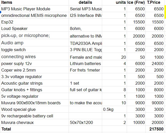
What materials and components will be used?
here is the list of material i will use:
Not to mention the PLA that will be used in the printing of a case.
Where will they come from?
Most of these will be purchased by the fablab.
If there is additional cost, i will cover.
All items can be found on local market. I have links to the shops where i can find them.
Items like hardwood boards will be procured by me going to the market place and picking them.
How much will they cost?
Items mentioned in the colored table have a cost estimation of around 220USDWhat parts and systems will be made?
As i mentioned:
The electornic part and,
the guitar frame
What processes will be used?
For the electronic part, I will program the SP32 to do tasks then connect the microphone and the speaker with its amplifier.
For the frame i will use the ShopBot to cut parts that i can.
Originally i had thought to make a mold and cast the tuning knobs but I was unable to find the right material for that.
Therefore i will buy the ready-made knobs, the strings and other things i will not be able to print.
Then i will assemble and test.
What questions need to be answered?
1. How to record sound/music and write it on an SD card?
2. How to immediately playback sound/ music?
3. Can the system be attached together?
4. Can the sound come out of the case?
How will it be evaluated?
My project should be evaluated on following criteria:
1. Is the sound coming out the one we recorded?
2. Does the system look like a guitar?
3. was it made by using computer controlled machines?
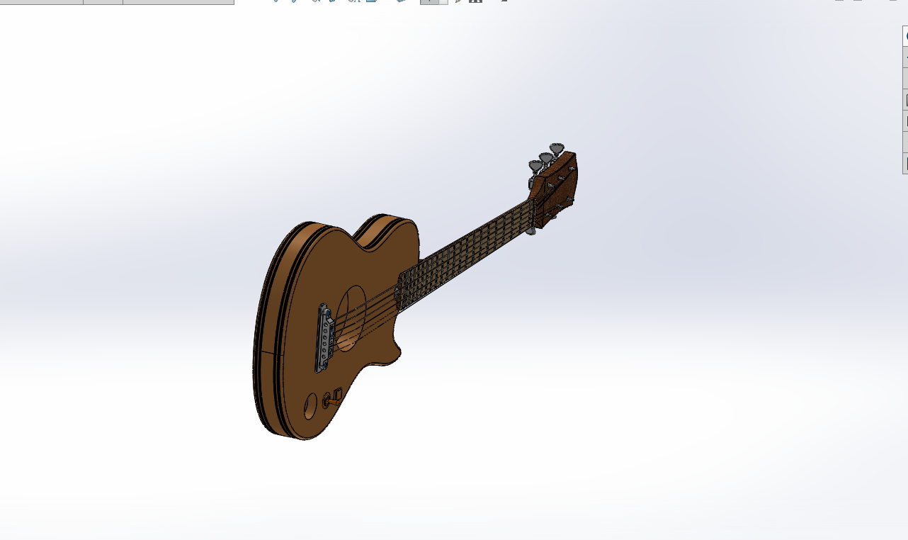
1. Strucutre of the guitar 3D design and CAM on CNC
Project design process
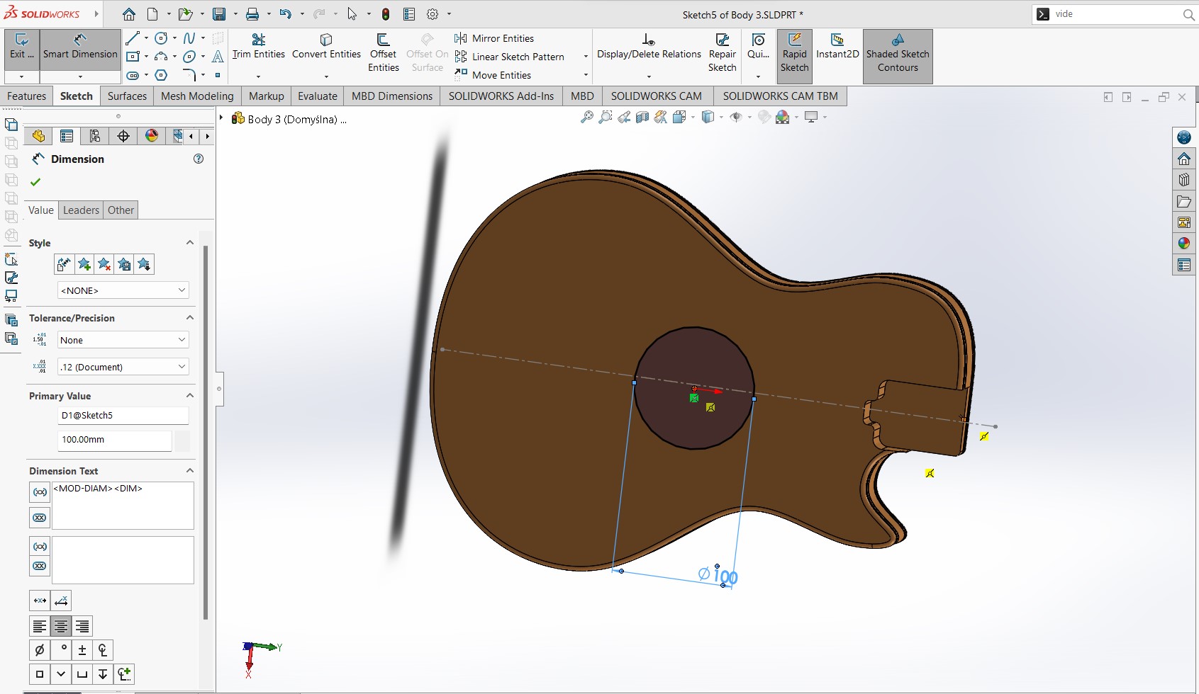
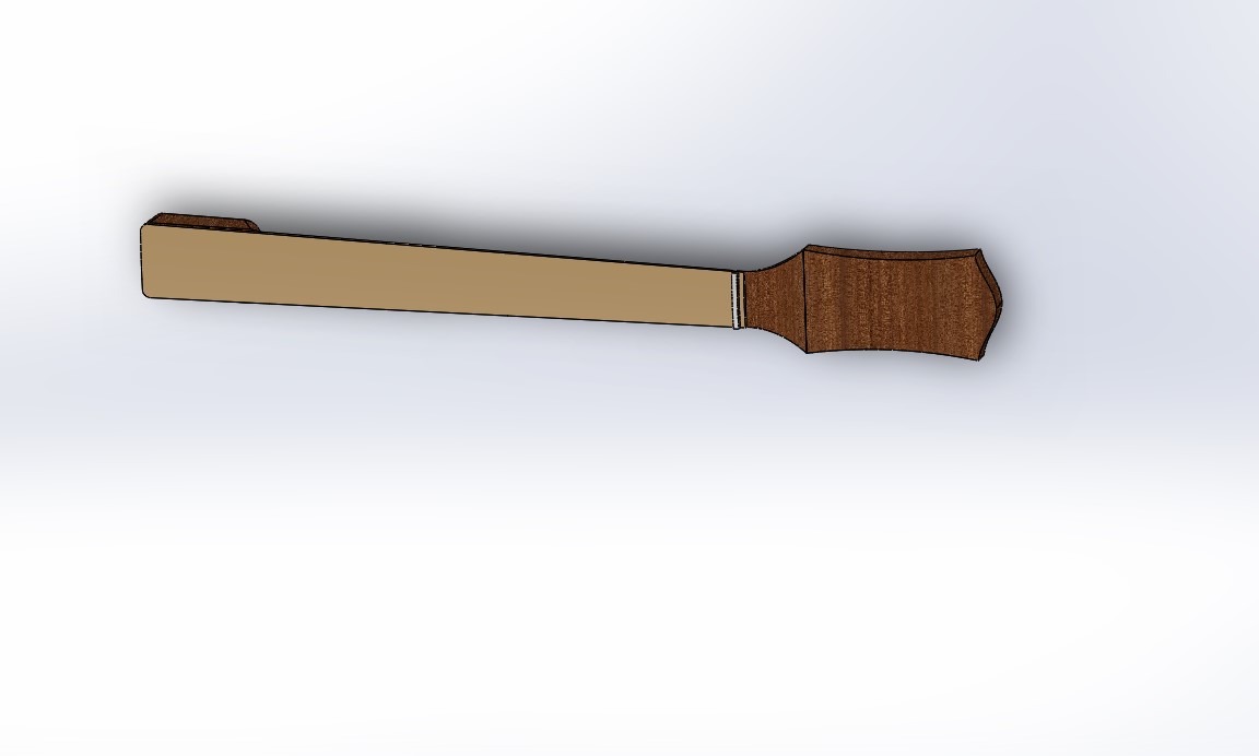
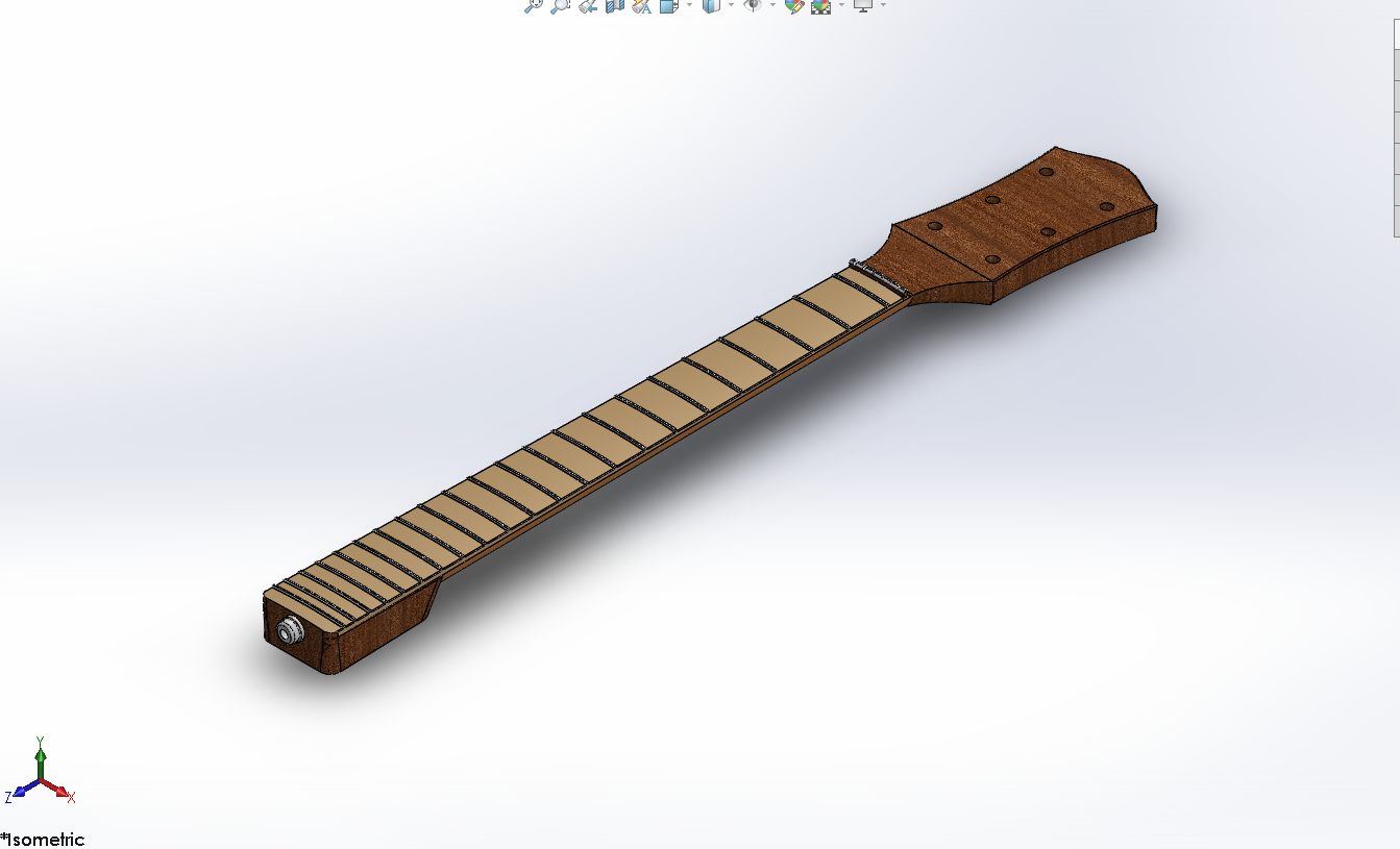
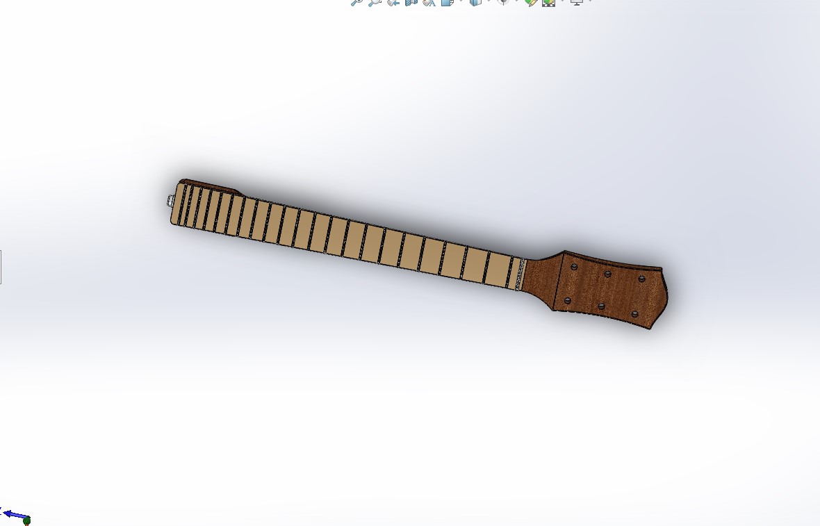
3D DESIGN
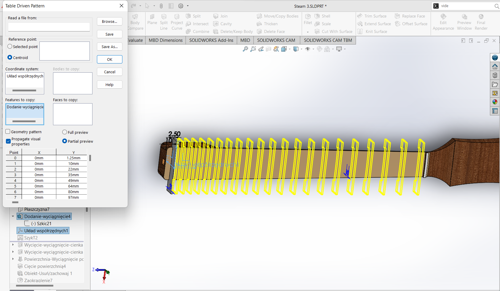
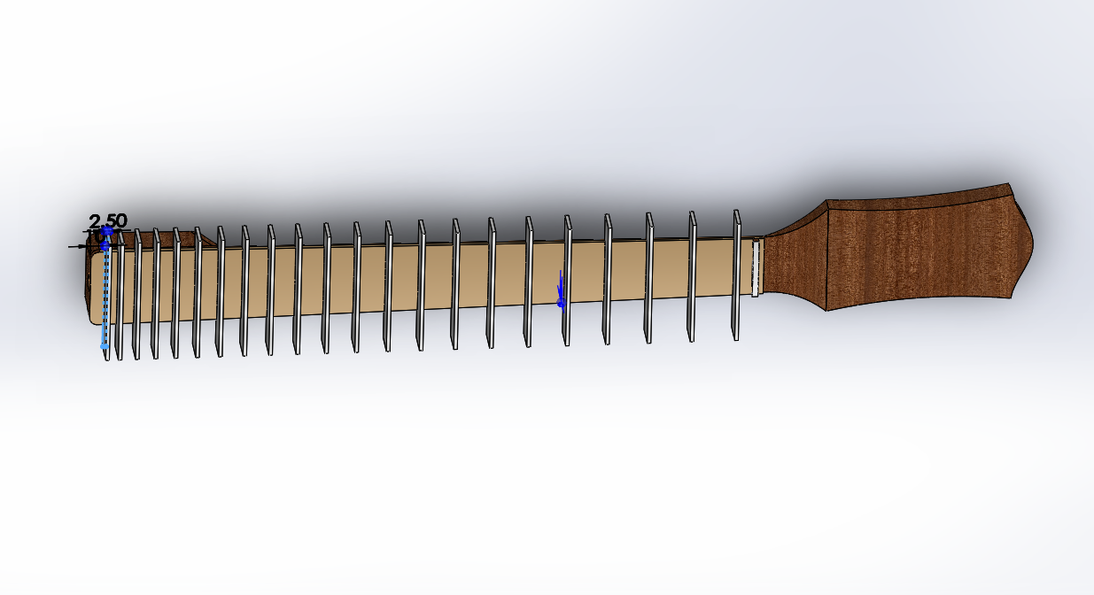
It is important to follow the common guide on the spacing between frets for Acoustic guitars.
So i used the table driven pattern in the design.
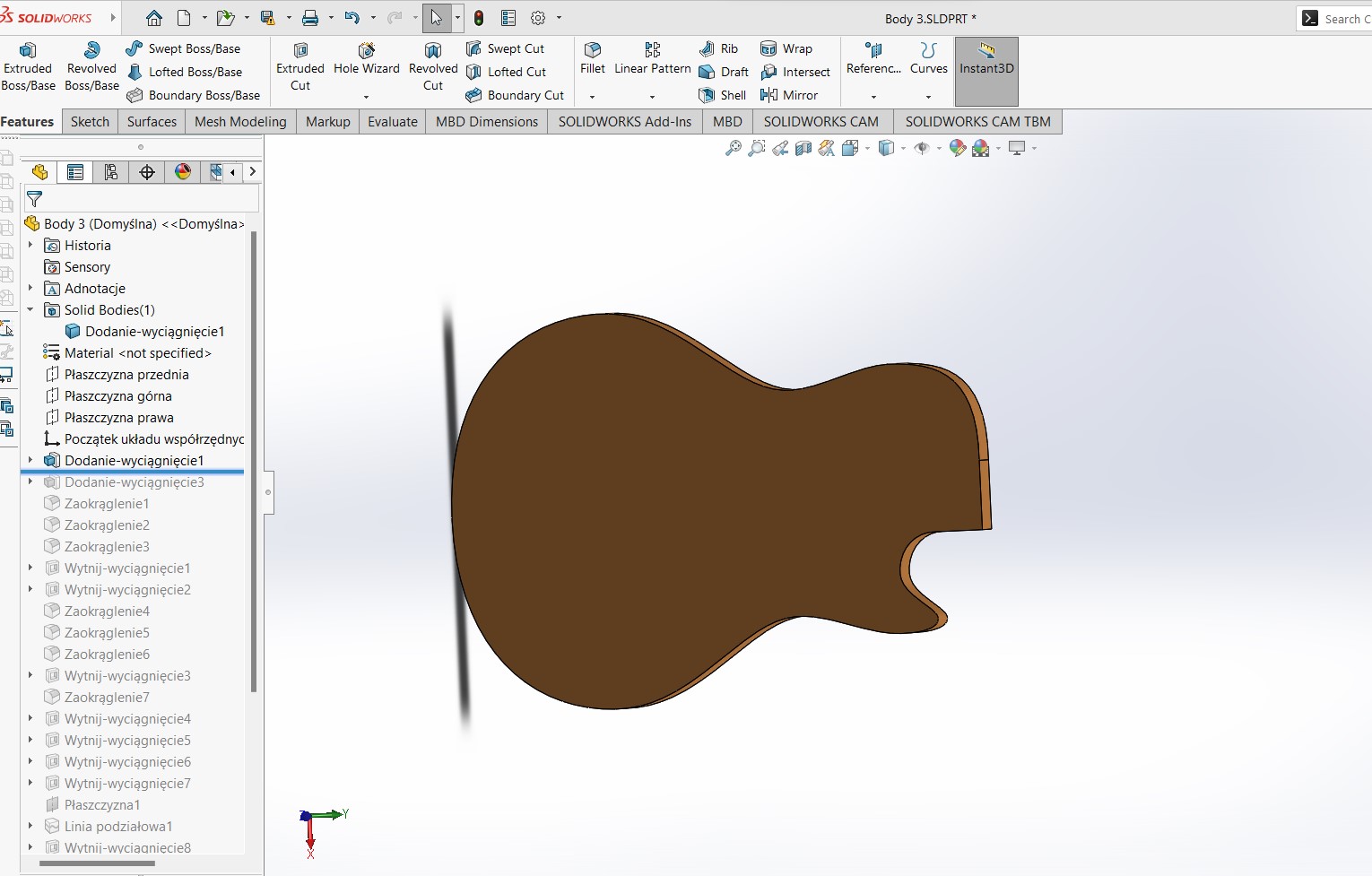
Video of the final design
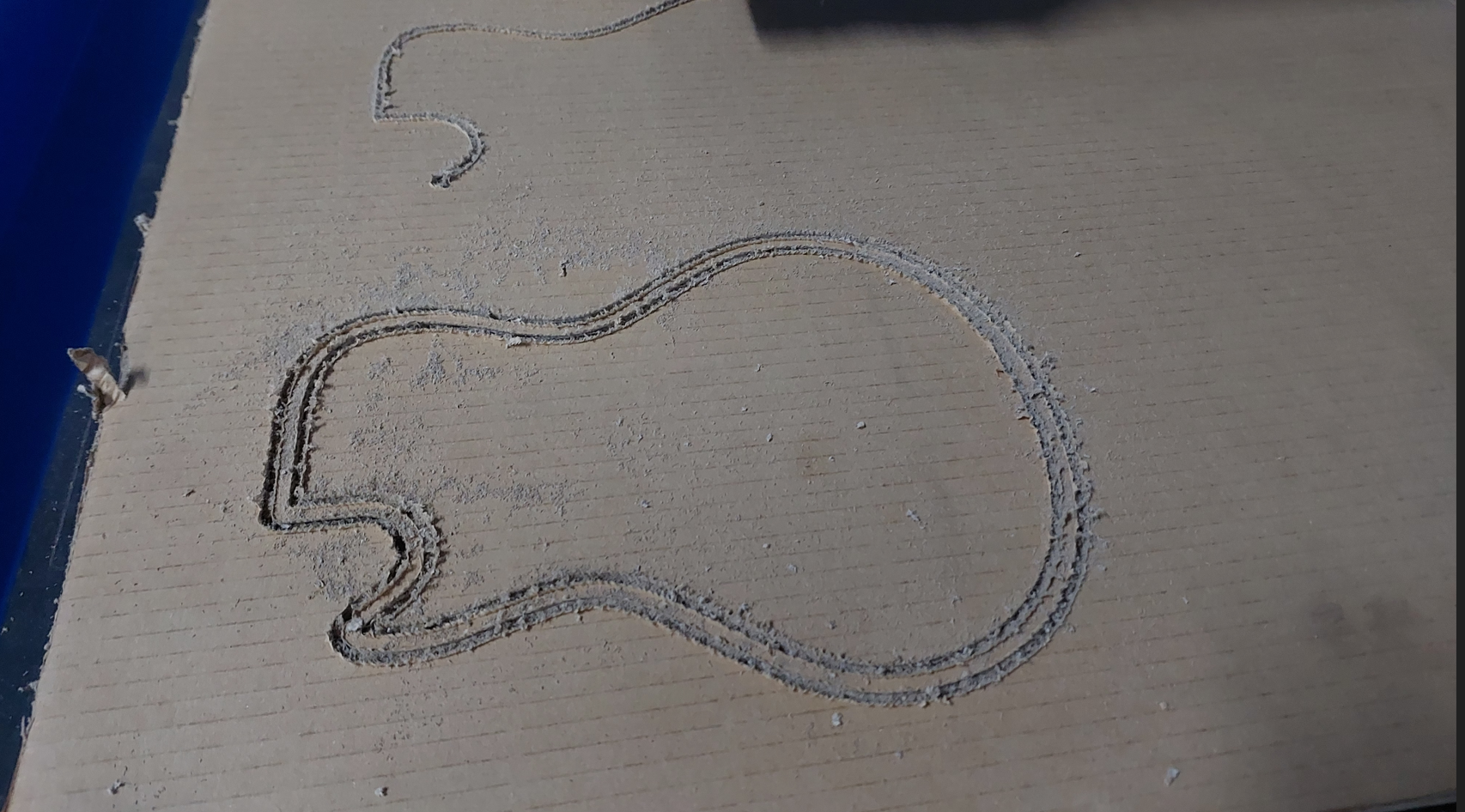
CNC
The whole guitar frame can be made using a DXF file to make the case on plywood with 3mm thickness
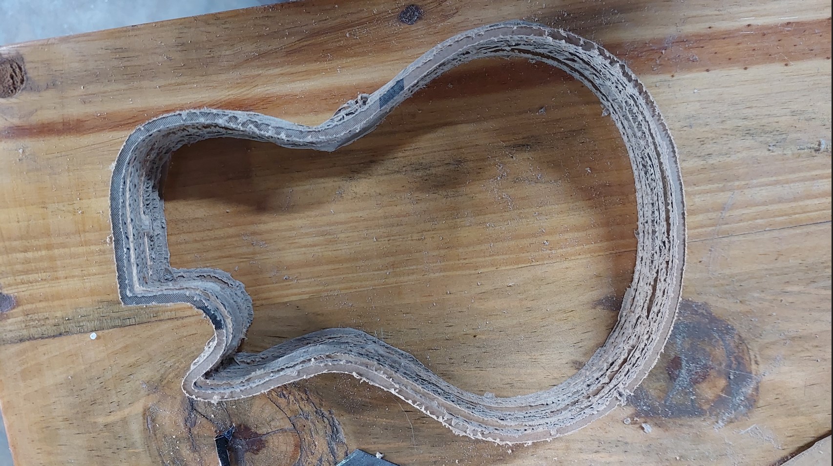
I started with cardboard to avoid wasting Material.
I stacked a number of similar parts on each other to have the shape
TBH, using a CNC to build a guitar(like everything) requires more expertise and tools.
Though the 3D designs are very comprehensive, i had to buy some of the parts.
Forexample there was no way of casting the guitar knobs in metal at the lab. Even if there'd been a way, i dont thing the results would have been that great, given that this is an industrial grate thing.
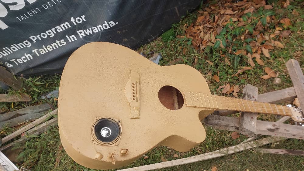
After all this is the frame i worked with
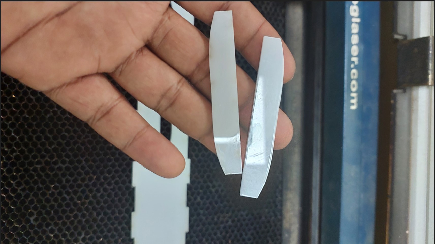
I Laser cut some parts
Among others:
The bridge where the strings will be laid.
Material: acrylic
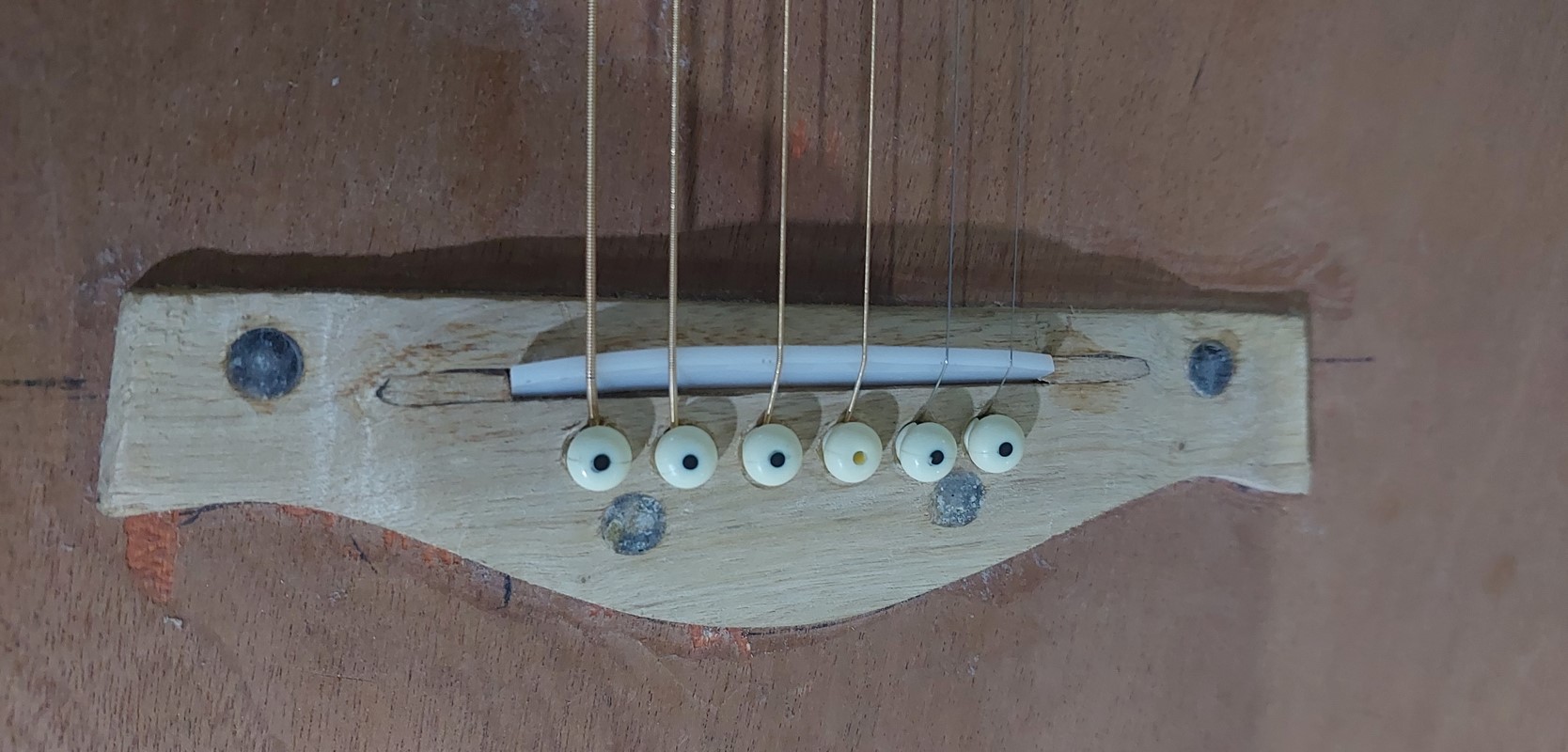
the bridge installed:
Also to have an idea of what will be done on the guital frame
Laser cut and engraved on the material on which the integration bos will rest
Electronics
As mentioned in the project development week,
it was too complicated for me to write music (audio) on an HC SD card using just SP32
I opted on using ISD1820 voice Module which records and plays back an audio input, then use the ESP32 to control a boutton like this:
Longpress: Start recording mode
Simplepress: playback the recorded music in loop indefinetely
I had to find a PCB board to house all my main components
The schematics i used. All files be included at the bottom.
The board side
3D view image of the board
Using Roland Miller (SRM20) was causin a lots of problem since the screw that holds the tool was not tightening and the bed seemed not well leveled.
I was using the usual process of importing svg into mods, creating mill traces and cuts, saving the g-code.
However, the results were not cool and i was near the presentation day!
Bad results from Rml
First outcome:
Second outcome
After long nights, this is why i decided to change the method and go to another CNC for Milling.
I opted to mill the PCB using a CNC
A blue elephant ELECNC6090 Chinese model.
Steps i took:
1. convert the exported svg of traces into a png file. I used inkscape and kept the ratio of 1:1 always
2. I used the Aspire CAM to create a pocket toolpath to clear the copper out and leave the traces alone.
3. I editted the tool diameter, the feedrate and plunge rate to match the board details. 0.16mm pocket depth to remove copper and 1.8mm to cut out the contour.
Using Aspire 10
clean traces of CNC
I felt happy of the outcome, considering the night i had spent trying the other machine that wouldn't work properly.
Please note that i recognize the health risks associated with milling PCB with this type of CNC.
If someone else has to do this, let them consider using serious PPE for their breathing
then SOLDERED components on
Uploaded in the control program
static const int buttonPin = 4; // switch pin
static const int Feedback_Pin = 18; // Feedback pin from ISD1820
int buttonStatePrevious = 1; // previousstate of the switch
unsigned long minButtonLongPressDuration = 600; // Time we wait before we see the press as a long press
unsigned long buttonLongPressMillis; // Time in ms when we the button was pressed
bool buttonStateLongPress = false; // True if it is a long press
const int intervalButton = 50; // Time between two readings of the button state
unsigned long previousButtonMillis; // Timestamp of the latest reading
unsigned long buttonPressDuration; // Time the button is pressed in ms
unsigned long currentMillis; // Variabele to store the number of milleseconds since the Arduino has started
unsigned long startRectime;
unsigned long EndRectime;
bool playE = false;
bool reco = false;
const int rec = 16;
const int play = 17;
int timer_del = 0;
int timerDel2 = 0;
int recState = 0;
int playState = 0;
int LED_INDICATOR = 5;
void setup() {
Serial.begin(115200);
pinMode(buttonPin, INPUT_PULLUP);
pinMode(rec, OUTPUT);
pinMode(play, OUTPUT);
pinMode(LED_INDICATOR,OUTPUT);
pinMode(Feedback_Pin, INPUT);
digitalWrite(rec, 0);
digitalWrite(play, playState);
}
// Function for reading the button state
void readButtonState() {
if (currentMillis - previousButtonMillis > intervalButton) {
int buttonState = digitalRead(buttonPin);
if (buttonState == 0 && buttonStatePrevious == 1 && !buttonStateLongPress) {
buttonLongPressMillis = currentMillis;
buttonStatePrevious = 0;
Serial.println("Button pressed");
}
buttonPressDuration = currentMillis - buttonLongPressMillis;
if (buttonState == 0 && !buttonStateLongPress && buttonPressDuration >= minButtonLongPressDuration) {
buttonStateLongPress = true;
buttonStatePrevious = 0;
Serial.println("Button long pressed");
getting_ready_for_record();
reco = true;
}
if (buttonState == 1 && buttonStatePrevious == 0) {
buttonStatePrevious = 1;
buttonStateLongPress = false;
digitalWrite(LED_INDICATOR, HIGH);
delay(500);
digitalWrite(LED_INDICATOR, LOW);
delay(500);
Serial.println("Button released");
if (buttonPressDuration < minButtonLongPressDuration) {
Serial.println("Button pressed shortly");
playE = true;
}
}
previousButtonMillis = currentMillis;
}
}
void loop() {
currentMillis = millis(); // store the current time
readButtonState(); // read the button state
digitalWrite(play, playState);
//if a single press occurs, playback starts looping
if (playE) {
playBack();
}
//if long pressed the button, record will start
if (reco) {
digitalWrite(LED_INDICATOR, HIGH);
record();
reco = false;
}
}
//recording function ---recording time may vary from 1 upto 20 seconds
void record() {
Serial.println("Recording");
long startTime = millis()/1000;
long duration = 20; //up to 20sec
while (millis()/1000 < startTime + duration) {
digitalWrite(rec, 1);
}
digitalWrite(rec, 0);
}
//playback function
void playBack() {
playState=1;
digitalWrite(play, playState);
int timer_delay=timer_del;
while(timer_delay>0){
playState = 0;
timer_delay=timer_delay-1;
digitalWrite(play, playState);
}
}
//
// if (playState == 1) {
// Serial.println("Playing");
// if (millis() / 1000 - timer_del >= 1) {
// playState = 0;
// timer_del = timer_del+(millis() / 1000);
// }
// } else {
// if (millis() / 1000 - timer_del >= 0.1) {
// playState = 1;
// timer_del = timer_del+(millis() / 1000);
// }
// }
//}
void getting_ready_for_record(){
int timer=1;
while(timer<=5){
digitalWrite(LED_INDICATOR, HIGH);
delay(500);
digitalWrite(LED_INDICATOR, LOW);
delay(500);
timer=timer+1;
}
startRectime=millis();
attachInterrupt(digitalPinToInterrupt(Feedback_Pin),recordingstate,RISING); // function for creating external interrupts at pin2 on Rising (LOW to HIGH vice versa)
}
void recordingstate(){
digitalWrite(LED_INDICATOR, LOW);
detachInterrupt(Feedback_Pin);
reco = false;
EndRectime=millis();
timer_del= (EndRectime-startRectime)/1000;
Serial.println("Recording ended with period of "+String(timer_del)+"sec");
}
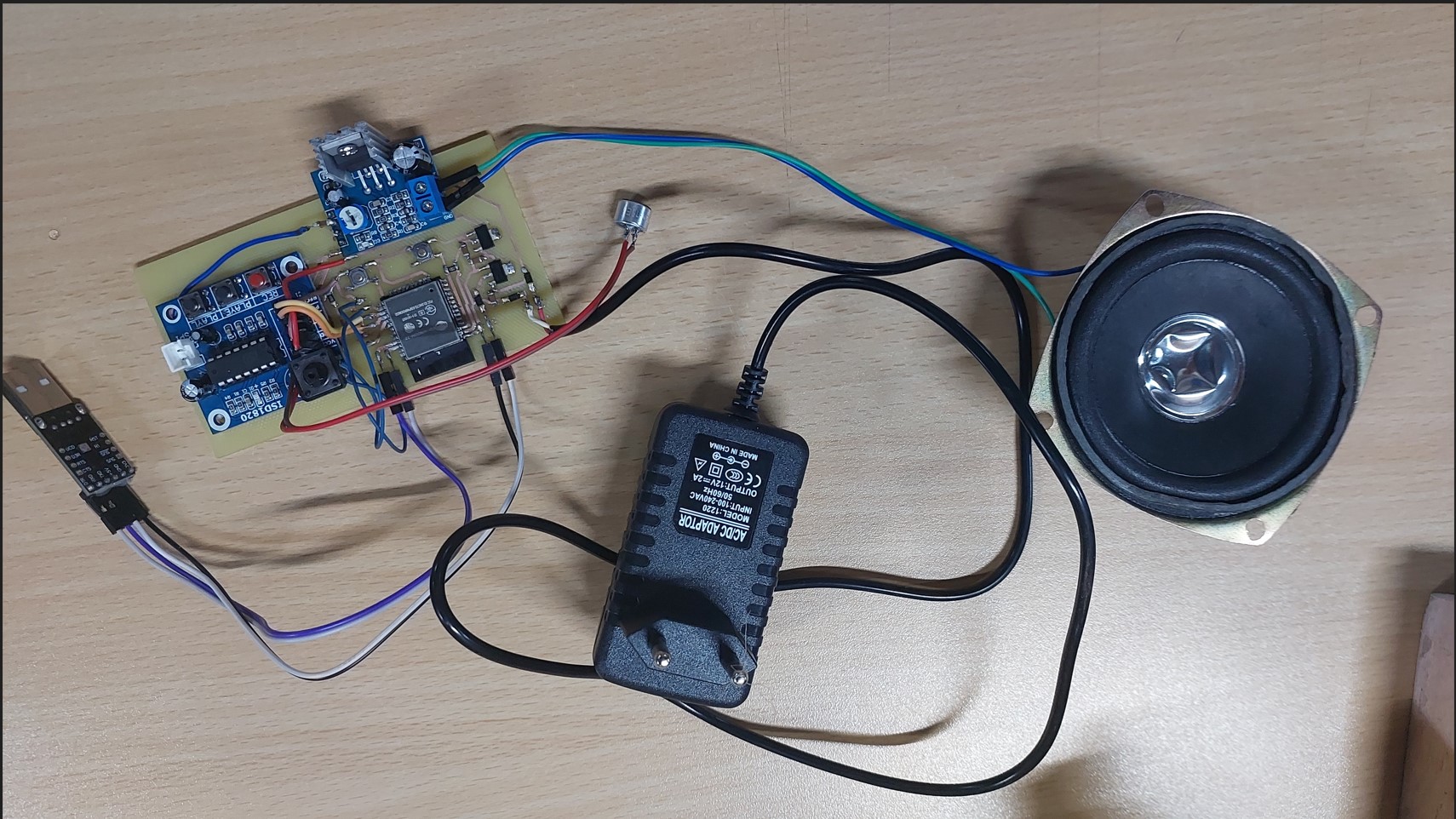
power options:
I use
7.3v to 12v for the audio amplifier
3.3v for the ESP32
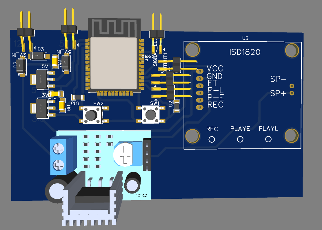
this board i designed has two regulators. One to convert 12v to 5V that does feed the ESP32
The 5V goes to the other regulator to convert the voltage to 3.3v.
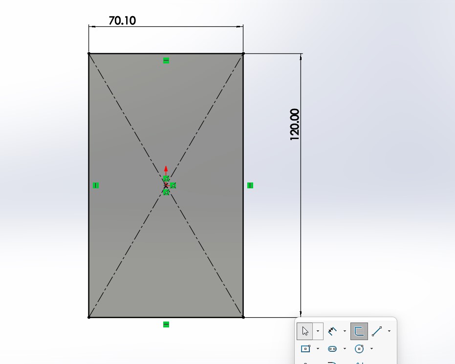
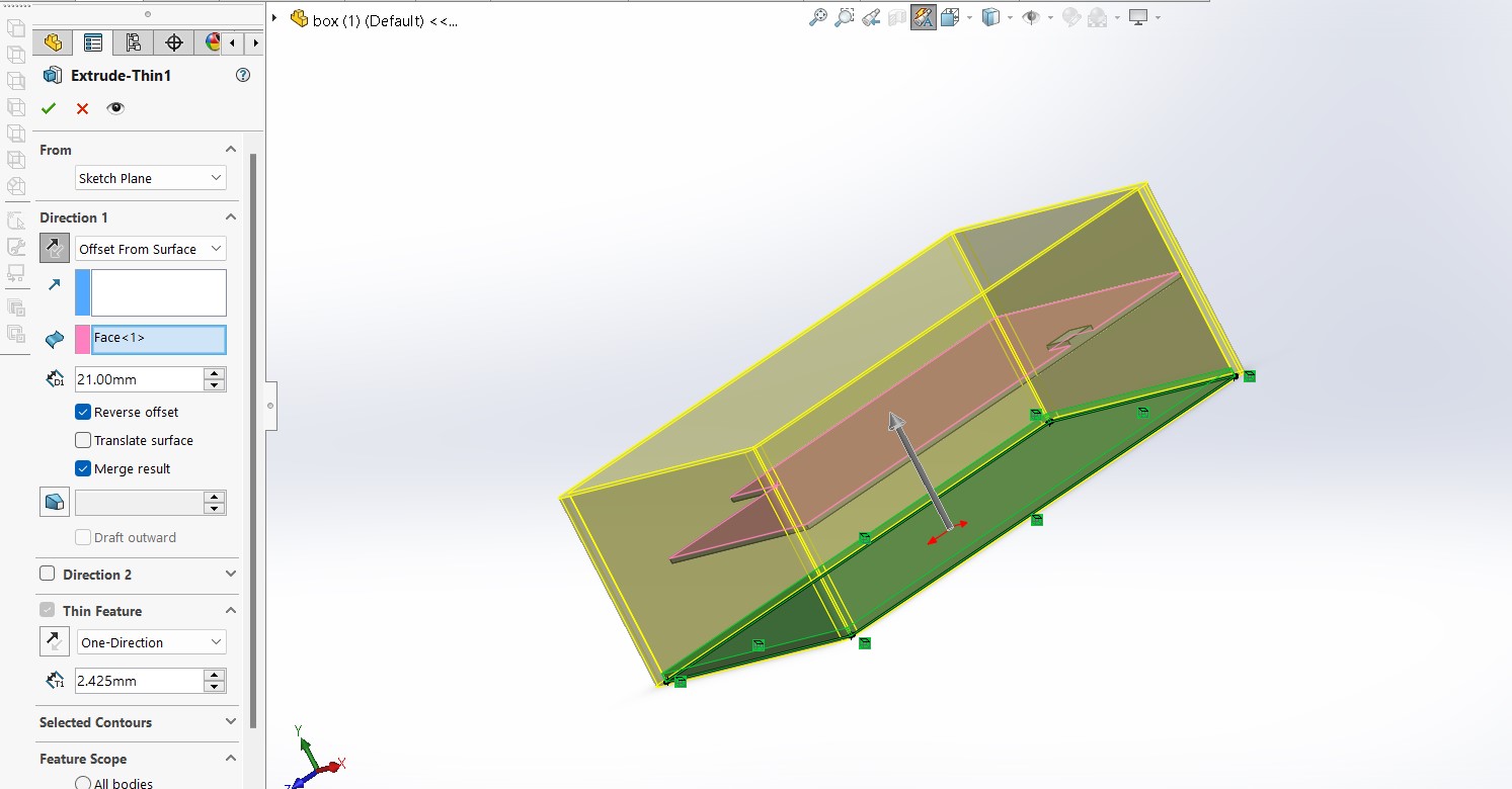
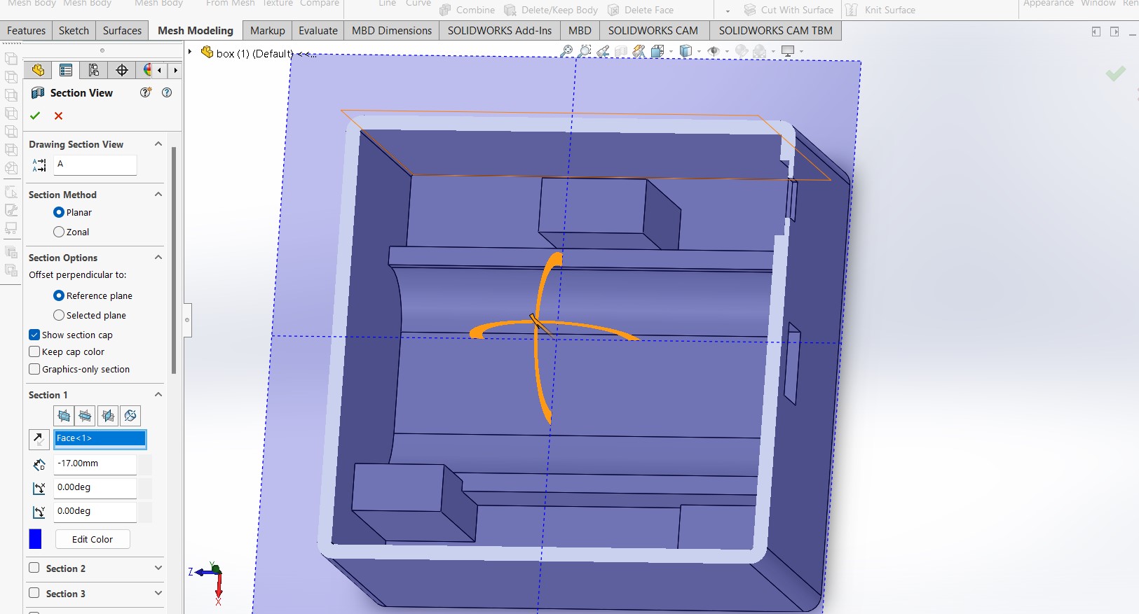
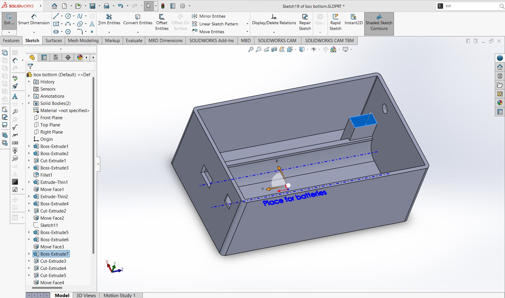
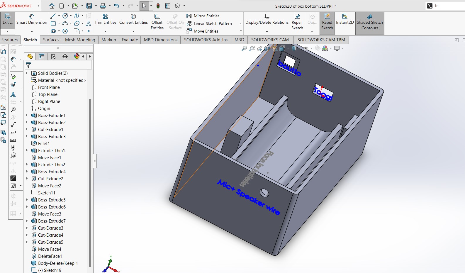
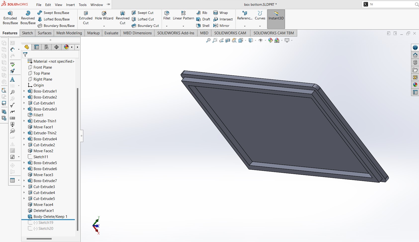
3D DESIGN AND PRINTING
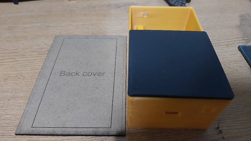
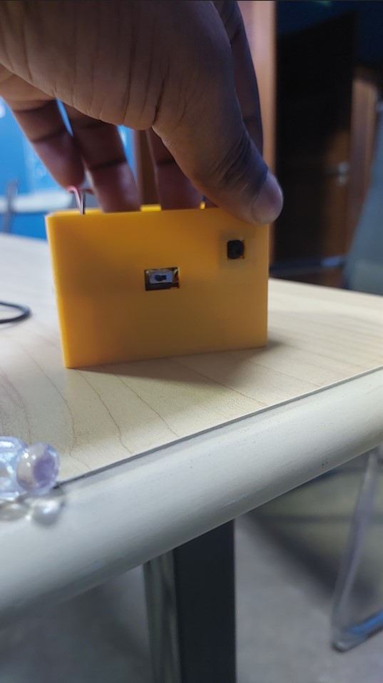
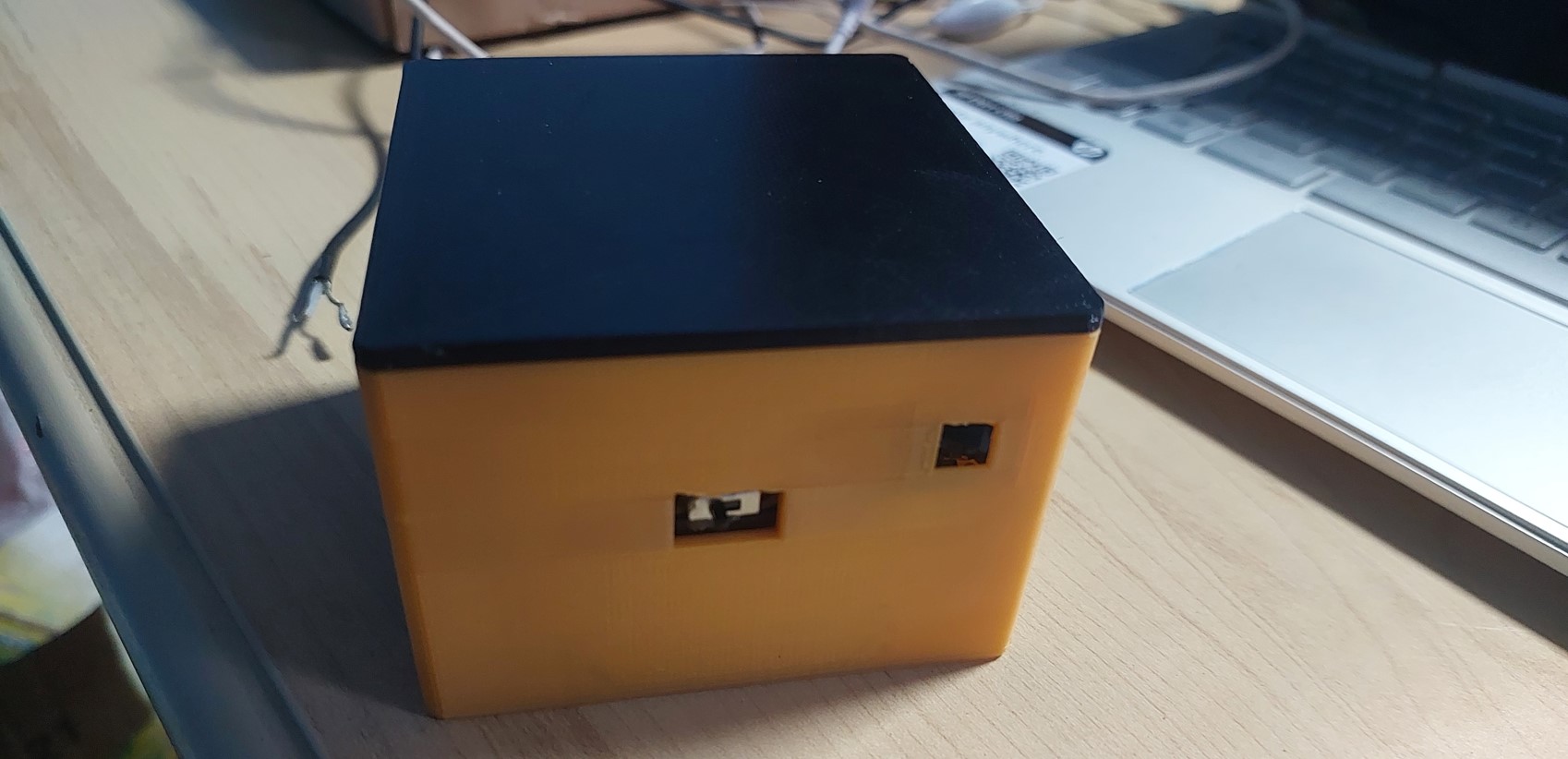
I designed the box in which the components will go
Box layers. Batteries and board
model
Wire and switch, button holes. annotations
Top
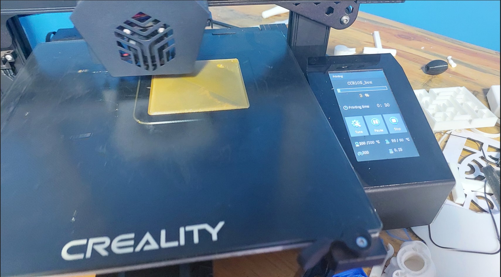
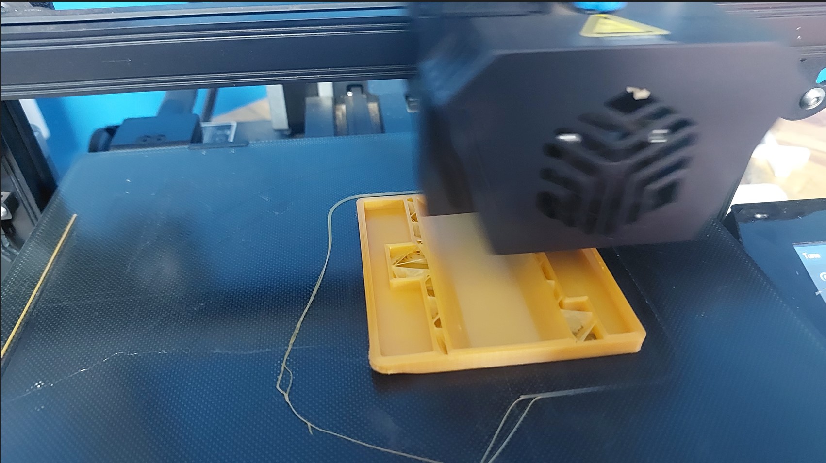
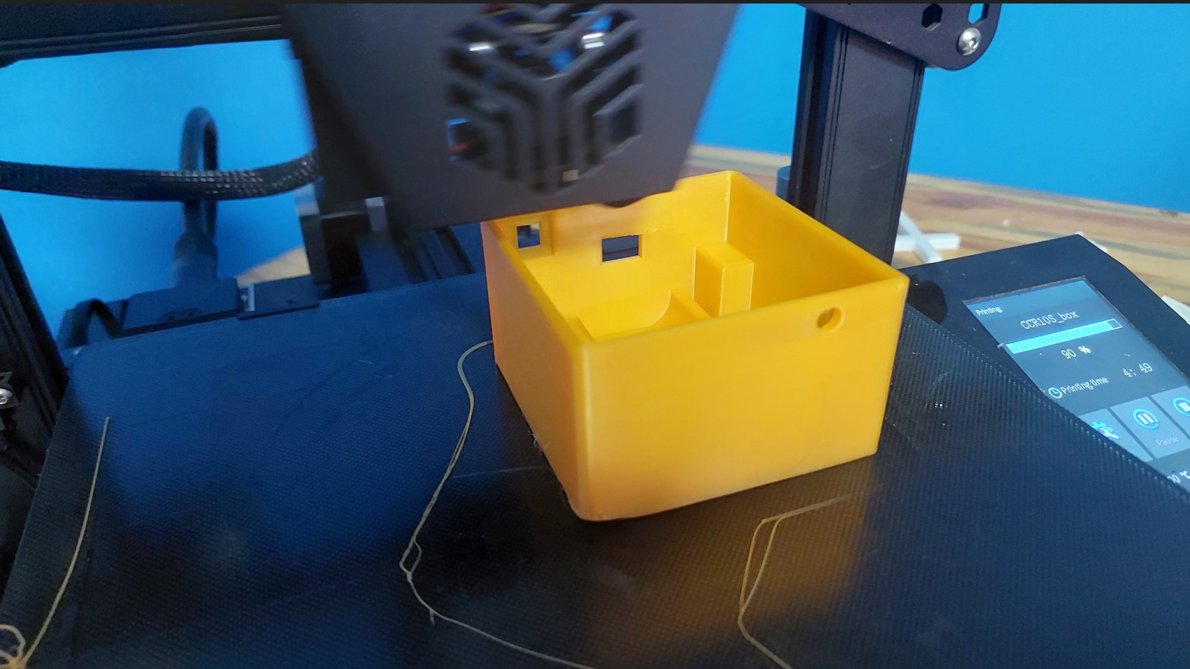
The box printing
Of course you take the stl files you want to print, slice it and take the g-code to the 3d printer.
I used standard quality on a PLA, i took about 9hours for the box and 3 hours for the top/cover.
The components fit in well
Assembly
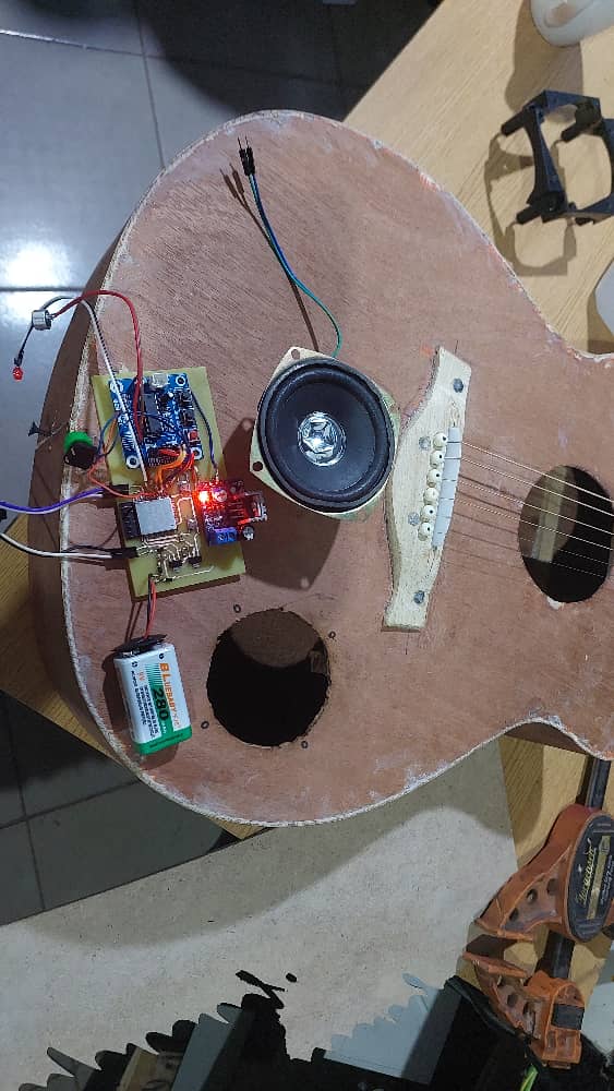
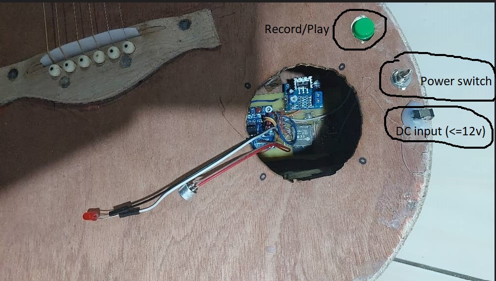
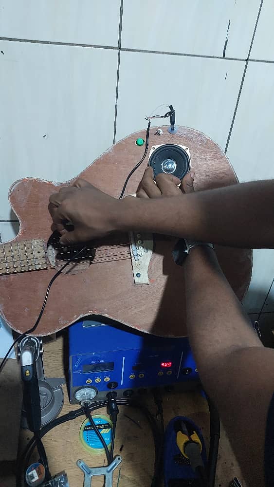
Integration
Put the components inside the guitar and Tested a bit more Before painting
Components will sit in down. As i lasercut the piece of material that i will glue on the back of the guitar from inside, i am okay.
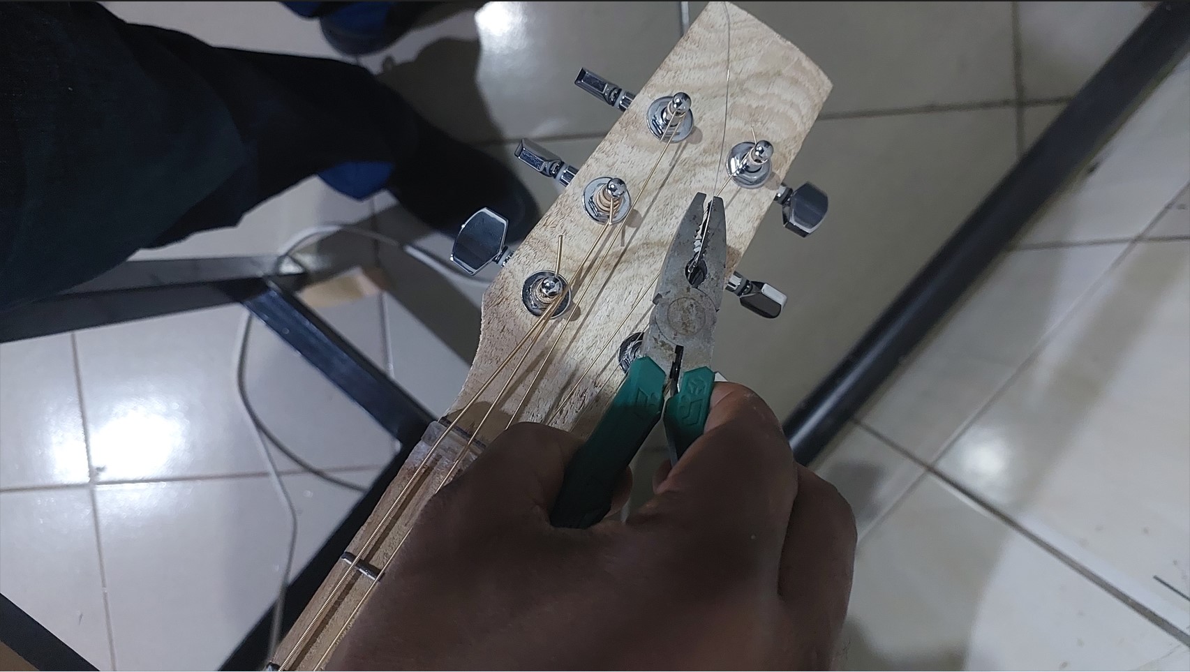
Trimming the strings
Final tests before putting the components inside and fix them
Before paintig, we test if everything works
Testing recording before i put the program section for a count down of an an LED to get ready.
this time you press the record button(longpress) and immediately start to record. However since the longpress has a range of seconds (2-4.9), it was hard to be precise.
that is why i added the LED for help the player to count down after the long press and know that when the LED stops blinking (5seconds) that's the time the recording starts.
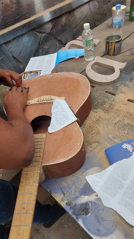
A friend helping me mask the speaker with paper and tape
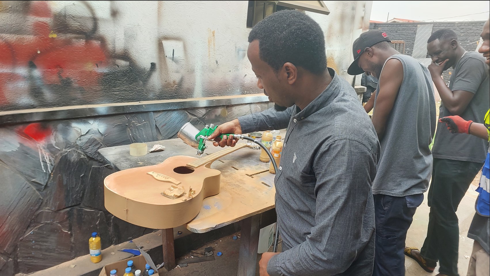
Mixed thiner with paint, usend a compressor to spray
It was a quick process, with a fair results
Let the paint dry for about 30 minutes under the sunlight
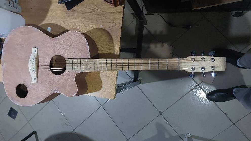
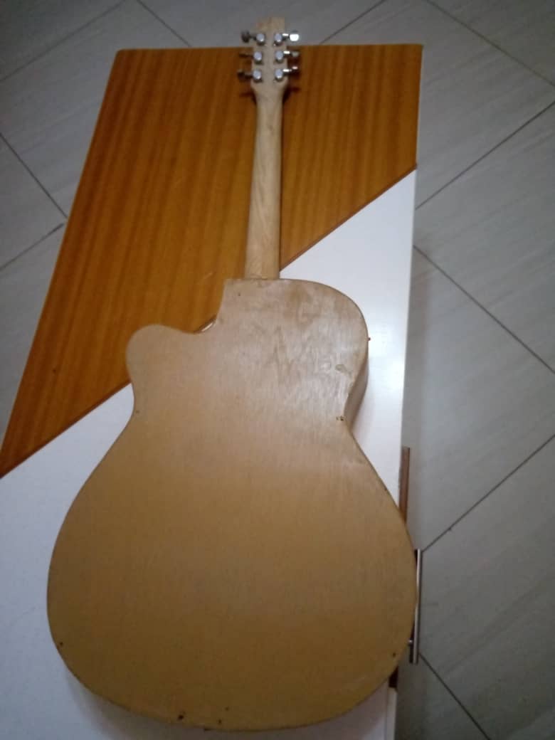
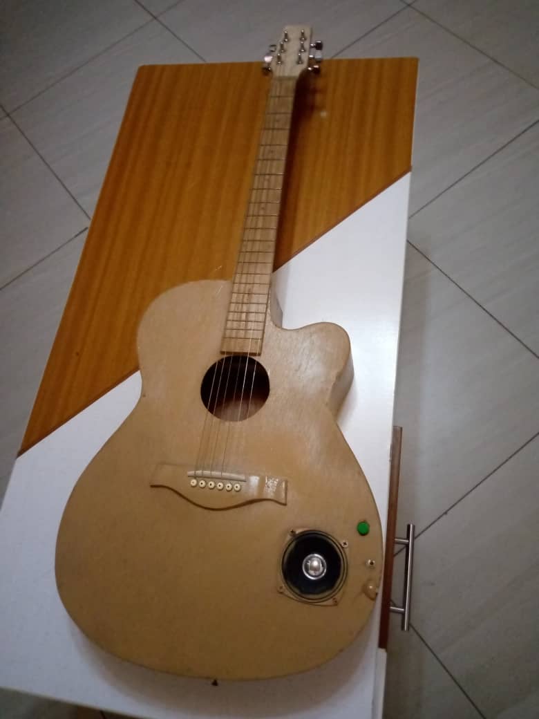
I put back the strings on and tested. It worked and it still workss!!!
Now the guitar works:
back
front
ZIPPED FILES
 Plan for dissemination of my project:
1. finish the embedded system part by Monday the 29th of May
2. Buy wood and cut the guitar by Saturday the 3rd June
3. Assembly and testing by sunday the 4th June
4. Make a video for final presentation before the 6th of June
5. Document everything about my final project before the 7th of June.
So far i have started working on the electronics part
I also sent in the request for material from the fablab
Plan for dissemination of my project:
1. finish the embedded system part by Monday the 29th of May
2. Buy wood and cut the guitar by Saturday the 3rd June
3. Assembly and testing by sunday the 4th June
4. Make a video for final presentation before the 6th of June
5. Document everything about my final project before the 7th of June.
So far i have started working on the electronics part
I also sent in the request for material from the fablab
 These are the shapes i cut on acrylic using a laser cutter to be able to visualize the project.
Thinking about my Summary slides
What will it do?
My proposed project is a guitar that has the capacity to record a piece of music and play it back on loop.
The user of the guitar may choose to play another live piece of music. Then it will sound like two pieces of music are playing at the same time.
Who's done what beforehand?
In the fab academy, I saw people who did the boom box, another one who did “Legos” for Sound
Physical Modular Sound Blocks for sound and music and many other projects.
However none of them resembled mine exactly.
On the market you may find guitar pedals with loops. However they are costly and it is a separate tool away from the guitar. MINE WILL BE INTEGRATED INSIDE A GUITAR.
What will you design?
1. I will design the electronic circuit for the whole process of recording, , playing back on a loop.
2. I will design the guitar frame: Acoustic version
3. Integrate everything together.
What materials and components will be used?
here is the list of material i will use:
These are the shapes i cut on acrylic using a laser cutter to be able to visualize the project.
Thinking about my Summary slides
What will it do?
My proposed project is a guitar that has the capacity to record a piece of music and play it back on loop.
The user of the guitar may choose to play another live piece of music. Then it will sound like two pieces of music are playing at the same time.
Who's done what beforehand?
In the fab academy, I saw people who did the boom box, another one who did “Legos” for Sound
Physical Modular Sound Blocks for sound and music and many other projects.
However none of them resembled mine exactly.
On the market you may find guitar pedals with loops. However they are costly and it is a separate tool away from the guitar. MINE WILL BE INTEGRATED INSIDE A GUITAR.
What will you design?
1. I will design the electronic circuit for the whole process of recording, , playing back on a loop.
2. I will design the guitar frame: Acoustic version
3. Integrate everything together.
What materials and components will be used?
here is the list of material i will use:
 Not to mention the PLA that will be used in the printing of a case.
Where will they come from?
Most of these will be purchased by the fablab.
If there is additional cost, i will cover.
All items can be found on local market. I have links to the shops where i can find them.
Items like hardwood boards will be procured by me going to the market place and picking them.
How much will they cost?
Items mentioned in the colored table have a cost estimation of around 220USD
What parts and systems will be made?
As i mentioned:
The electornic part and,
the guitar frame
What processes will be used?
For the electronic part, I will program the SP32 to do tasks then connect the microphone and the speaker with its amplifier.
For the frame i will use the ShopBot to cut parts that i can.
Originally i had thought to make a mold and cast the tuning knobs but I was unable to find the right material for that.
Therefore i will buy the ready-made knobs, the strings and other things i will not be able to print.
Then i will assemble and test.
What questions need to be answered?
1. How to record sound/music and write it on an SD card?
2. How to immediately playback sound/ music?
3. Can the system be attached together?
4. Can the sound come out of the case?
How will it be evaluated?
My project should be evaluated on following criteria:
1. Is the sound coming out the one we recorded?
2. Does the system look like a guitar?
3. was it made by using computer controlled machines?
Not to mention the PLA that will be used in the printing of a case.
Where will they come from?
Most of these will be purchased by the fablab.
If there is additional cost, i will cover.
All items can be found on local market. I have links to the shops where i can find them.
Items like hardwood boards will be procured by me going to the market place and picking them.
How much will they cost?
Items mentioned in the colored table have a cost estimation of around 220USD
What parts and systems will be made?
As i mentioned:
The electornic part and,
the guitar frame
What processes will be used?
For the electronic part, I will program the SP32 to do tasks then connect the microphone and the speaker with its amplifier.
For the frame i will use the ShopBot to cut parts that i can.
Originally i had thought to make a mold and cast the tuning knobs but I was unable to find the right material for that.
Therefore i will buy the ready-made knobs, the strings and other things i will not be able to print.
Then i will assemble and test.
What questions need to be answered?
1. How to record sound/music and write it on an SD card?
2. How to immediately playback sound/ music?
3. Can the system be attached together?
4. Can the sound come out of the case?
How will it be evaluated?
My project should be evaluated on following criteria:
1. Is the sound coming out the one we recorded?
2. Does the system look like a guitar?
3. was it made by using computer controlled machines?
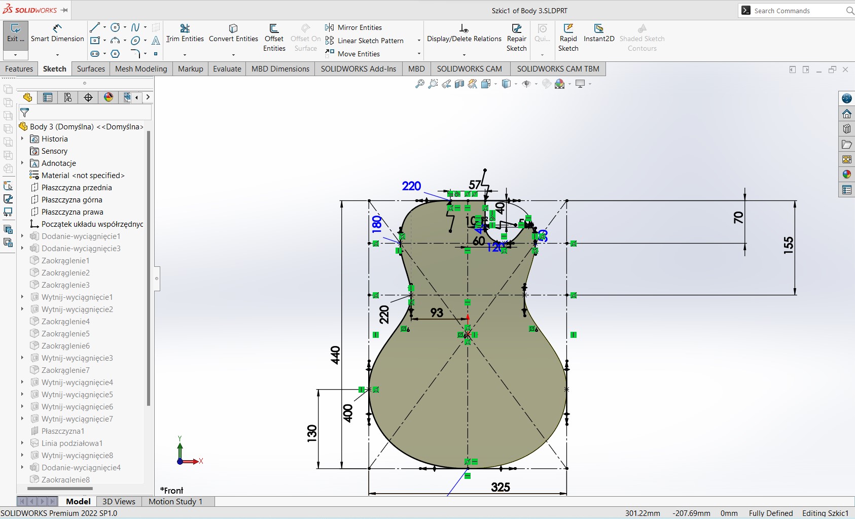
 It is important to follow the common guide on the spacing between frets for Acoustic guitars.
So i used the table driven pattern in the design.
It is important to follow the common guide on the spacing between frets for Acoustic guitars.
So i used the table driven pattern in the design.

 Video of the final design

 I stacked a number of similar parts on each other to have the shape
 TBH, using a CNC to build a guitar(like everything) requires more expertise and tools.
Though the 3D designs are very comprehensive, i had to buy some of the parts.
Forexample there was no way of casting the guitar knobs in metal at the lab. Even if there'd been a way, i dont thing the results would have been that great, given that this is an industrial grate thing.
After all this is the frame i worked with
TBH, using a CNC to build a guitar(like everything) requires more expertise and tools.
Though the 3D designs are very comprehensive, i had to buy some of the parts.
Forexample there was no way of casting the guitar knobs in metal at the lab. Even if there'd been a way, i dont thing the results would have been that great, given that this is an industrial grate thing.
After all this is the frame i worked with
 the bridge installed:
 Also to have an idea of what will be done on the guital frame
 Laser cut and engraved on the material on which the integration bos will rest
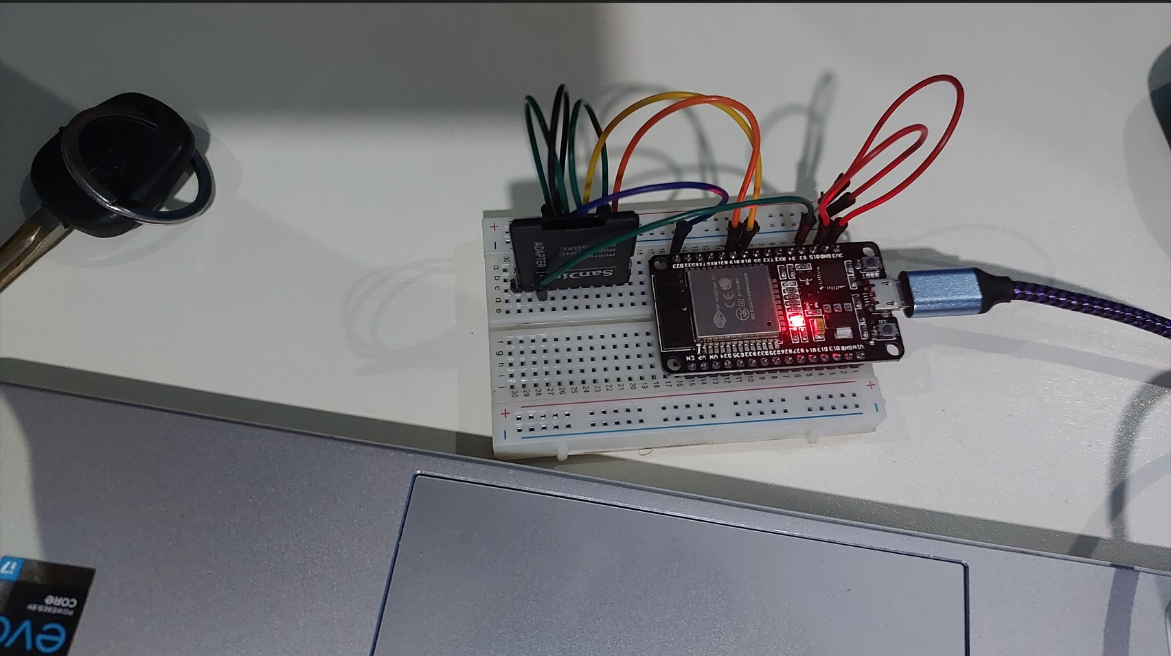 I opted on using ISD1820 voice Module which records and plays back an audio input, then use the ESP32 to control a boutton like this:
Longpress: Start recording mode
Simplepress: playback the recorded music in loop indefinetely
I had to find a PCB board to house all my main components
I opted on using ISD1820 voice Module which records and plays back an audio input, then use the ESP32 to control a boutton like this:
Longpress: Start recording mode
Simplepress: playback the recorded music in loop indefinetely
I had to find a PCB board to house all my main components
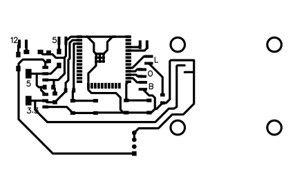 The schematics i used. All files be included at the bottom.
 The board side
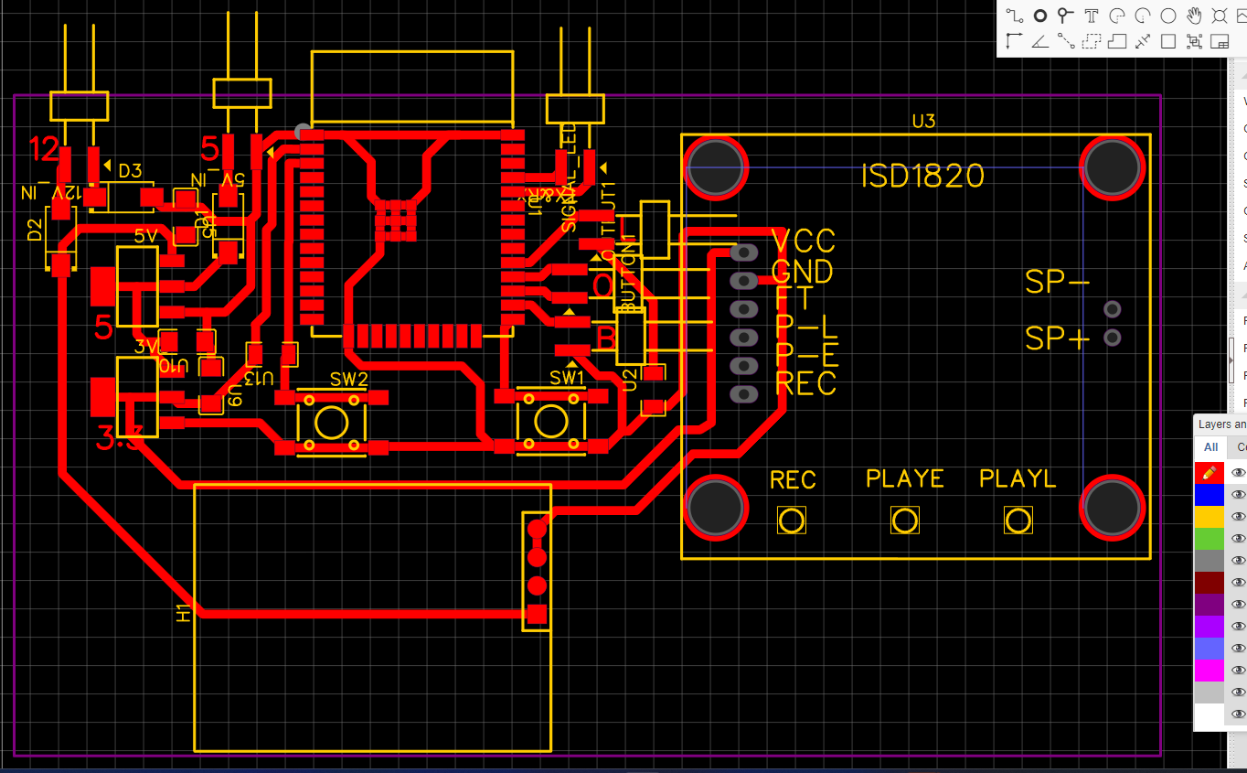 3D view image of the board
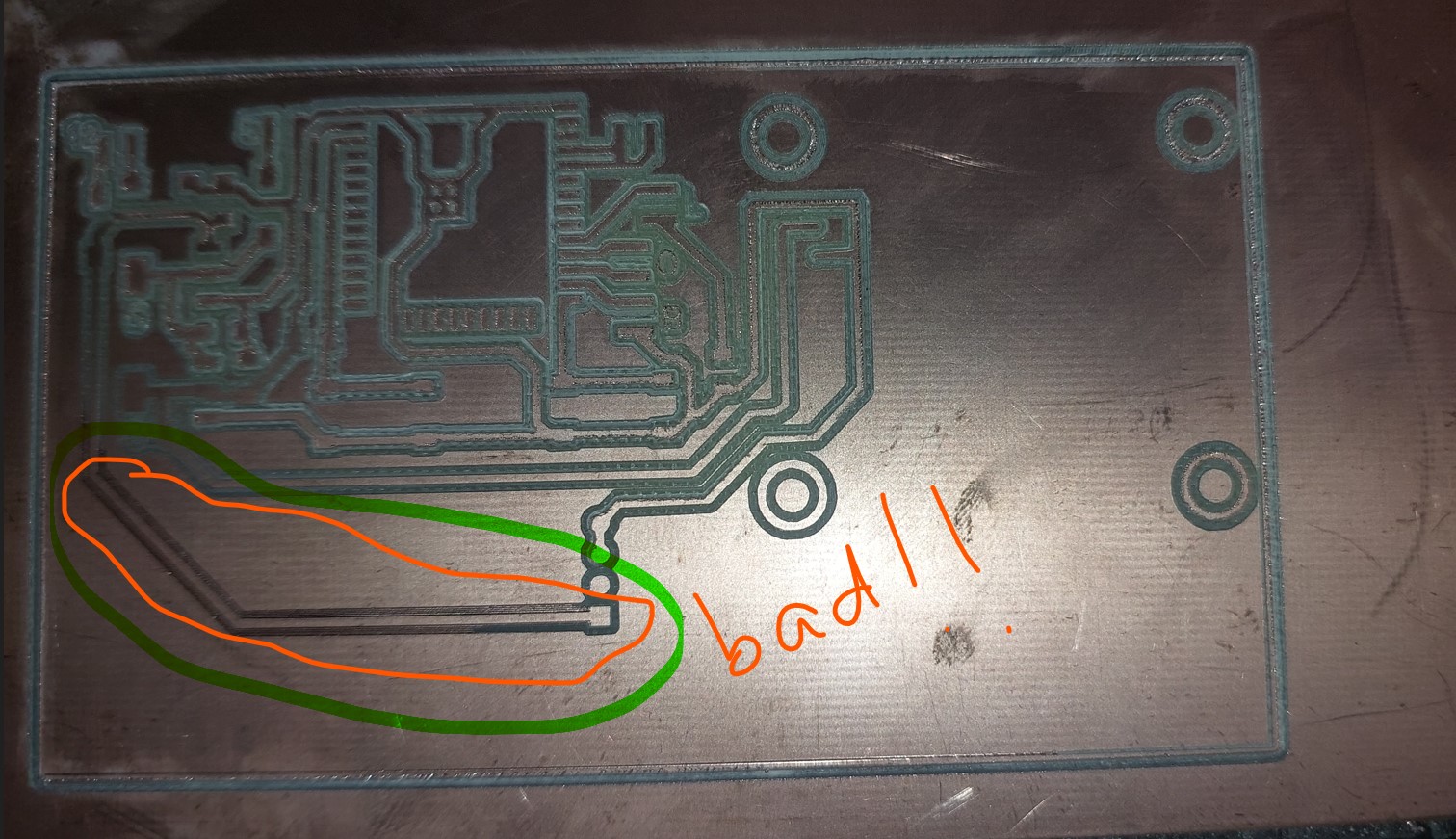
 Using Roland Miller (SRM20) was causin a lots of problem since the screw that holds the tool was not tightening and the bed seemed not well leveled.
I was using the usual process of importing svg into mods, creating mill traces and cuts, saving the g-code.
However, the results were not cool and i was near the presentation day!
Bad results from Rml
Using Roland Miller (SRM20) was causin a lots of problem since the screw that holds the tool was not tightening and the bed seemed not well leveled.
I was using the usual process of importing svg into mods, creating mill traces and cuts, saving the g-code.
However, the results were not cool and i was near the presentation day!
Bad results from Rml
 First outcome:
 Second outcome
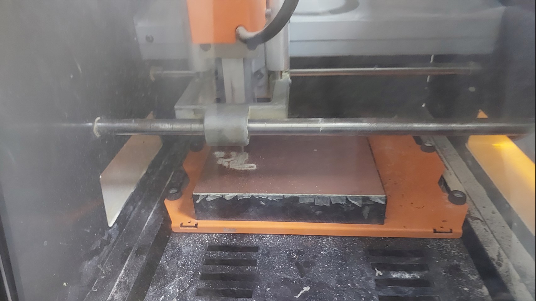
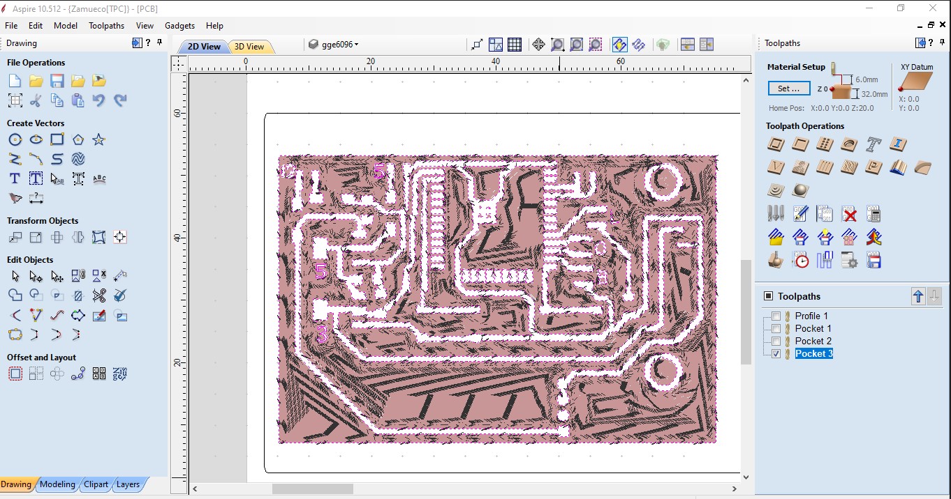
 After long nights, this is why i decided to change the method and go to another CNC for Milling.
I opted to mill the PCB using a CNC
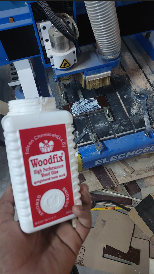
A blue elephant ELECNC6090 Chinese model.
Steps i took:
1. convert the exported svg of traces into a png file. I used inkscape and kept the ratio of 1:1 always
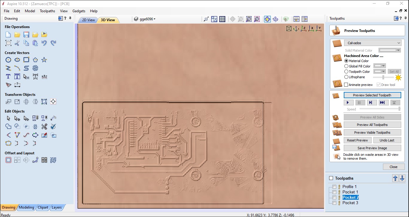
2. I used the Aspire CAM to create a pocket toolpath to clear the copper out and leave the traces alone.
3. I editted the tool diameter, the feedrate and plunge rate to match the board details. 0.16mm pocket depth to remove copper and 1.8mm to cut out the contour.
Using Aspire 10
After long nights, this is why i decided to change the method and go to another CNC for Milling.
I opted to mill the PCB using a CNC
A blue elephant ELECNC6090 Chinese model.
Steps i took:
1. convert the exported svg of traces into a png file. I used inkscape and kept the ratio of 1:1 always
2. I used the Aspire CAM to create a pocket toolpath to clear the copper out and leave the traces alone.
3. I editted the tool diameter, the feedrate and plunge rate to match the board details. 0.16mm pocket depth to remove copper and 1.8mm to cut out the contour.
Using Aspire 10
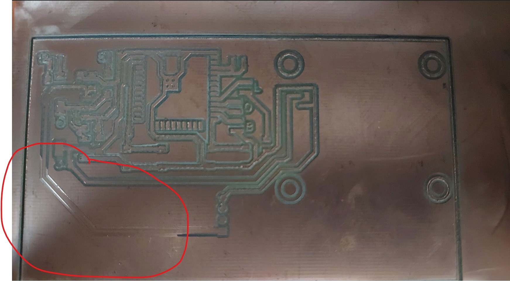
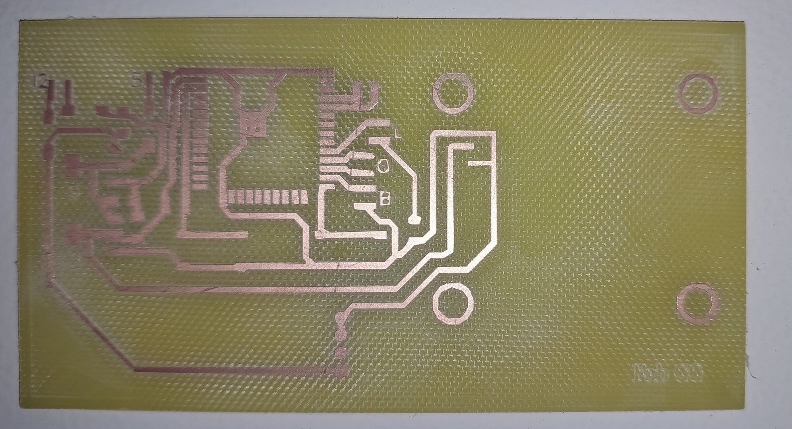
 clean traces of CNC
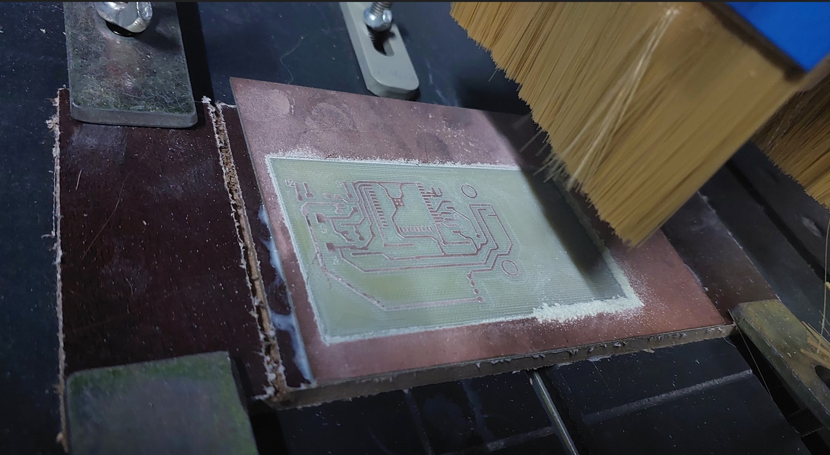 I felt happy of the outcome, considering the night i had spent trying the other machine that wouldn't work properly.
 Please note that i recognize the health risks associated with milling PCB with this type of CNC.
If someone else has to do this, let them consider using serious PPE for their breathing
Please note that i recognize the health risks associated with milling PCB with this type of CNC.
If someone else has to do this, let them consider using serious PPE for their breathing
 then SOLDERED components on
 Uploaded in the control program
static const int buttonPin = 4; // switch pin
static const int Feedback_Pin = 18; // Feedback pin from ISD1820
int buttonStatePrevious = 1; // previousstate of the switch
unsigned long minButtonLongPressDuration = 600; // Time we wait before we see the press as a long press
unsigned long buttonLongPressMillis; // Time in ms when we the button was pressed
bool buttonStateLongPress = false; // True if it is a long press
const int intervalButton = 50; // Time between two readings of the button state
unsigned long previousButtonMillis; // Timestamp of the latest reading
unsigned long buttonPressDuration; // Time the button is pressed in ms
unsigned long currentMillis; // Variabele to store the number of milleseconds since the Arduino has started
unsigned long startRectime;
unsigned long EndRectime;
bool playE = false;
bool reco = false;
const int rec = 16;
const int play = 17;
int timer_del = 0;
int timerDel2 = 0;
int recState = 0;
int playState = 0;
int LED_INDICATOR = 5;
void setup() {
Serial.begin(115200);
pinMode(buttonPin, INPUT_PULLUP);
pinMode(rec, OUTPUT);
pinMode(play, OUTPUT);
pinMode(LED_INDICATOR,OUTPUT);
pinMode(Feedback_Pin, INPUT);
digitalWrite(rec, 0);
digitalWrite(play, playState);
}
// Function for reading the button state
void readButtonState() {
if (currentMillis - previousButtonMillis > intervalButton) {
int buttonState = digitalRead(buttonPin);
if (buttonState == 0 && buttonStatePrevious == 1 && !buttonStateLongPress) {
buttonLongPressMillis = currentMillis;
buttonStatePrevious = 0;
Serial.println("Button pressed");
}
buttonPressDuration = currentMillis - buttonLongPressMillis;
if (buttonState == 0 && !buttonStateLongPress && buttonPressDuration >= minButtonLongPressDuration) {
buttonStateLongPress = true;
buttonStatePrevious = 0;
Serial.println("Button long pressed");
getting_ready_for_record();
reco = true;
}
if (buttonState == 1 && buttonStatePrevious == 0) {
buttonStatePrevious = 1;
buttonStateLongPress = false;
digitalWrite(LED_INDICATOR, HIGH);
delay(500);
digitalWrite(LED_INDICATOR, LOW);
delay(500);
Serial.println("Button released");
if (buttonPressDuration < minButtonLongPressDuration) {
Serial.println("Button pressed shortly");
playE = true;
}
}
previousButtonMillis = currentMillis;
}
}
void loop() {
currentMillis = millis(); // store the current time
readButtonState(); // read the button state
digitalWrite(play, playState);
//if a single press occurs, playback starts looping
if (playE) {
playBack();
}
//if long pressed the button, record will start
if (reco) {
digitalWrite(LED_INDICATOR, HIGH);
record();
reco = false;
}
}
//recording function ---recording time may vary from 1 upto 20 seconds
void record() {
Serial.println("Recording");
long startTime = millis()/1000;
long duration = 20; //up to 20sec
while (millis()/1000 < startTime + duration) {
digitalWrite(rec, 1);
}
digitalWrite(rec, 0);
}
//playback function
void playBack() {
playState=1;
digitalWrite(play, playState);
int timer_delay=timer_del;
while(timer_delay>0){
playState = 0;
timer_delay=timer_delay-1;
digitalWrite(play, playState);
}
}
//
// if (playState == 1) {
// Serial.println("Playing");
// if (millis() / 1000 - timer_del >= 1) {
// playState = 0;
// timer_del = timer_del+(millis() / 1000);
// }
// } else {
// if (millis() / 1000 - timer_del >= 0.1) {
// playState = 1;
// timer_del = timer_del+(millis() / 1000);
// }
// }
//}
void getting_ready_for_record(){
int timer=1;
while(timer<=5){
digitalWrite(LED_INDICATOR, HIGH);
delay(500);
digitalWrite(LED_INDICATOR, LOW);
delay(500);
timer=timer+1;
}
startRectime=millis();
attachInterrupt(digitalPinToInterrupt(Feedback_Pin),recordingstate,RISING); // function for creating external interrupts at pin2 on Rising (LOW to HIGH vice versa)
}
void recordingstate(){
digitalWrite(LED_INDICATOR, LOW);
detachInterrupt(Feedback_Pin);
reco = false;
EndRectime=millis();
timer_del= (EndRectime-startRectime)/1000;
Serial.println("Recording ended with period of "+String(timer_del)+"sec");
}
Uploaded in the control program
static const int buttonPin = 4; // switch pin
static const int Feedback_Pin = 18; // Feedback pin from ISD1820
int buttonStatePrevious = 1; // previousstate of the switch
unsigned long minButtonLongPressDuration = 600; // Time we wait before we see the press as a long press
unsigned long buttonLongPressMillis; // Time in ms when we the button was pressed
bool buttonStateLongPress = false; // True if it is a long press
const int intervalButton = 50; // Time between two readings of the button state
unsigned long previousButtonMillis; // Timestamp of the latest reading
unsigned long buttonPressDuration; // Time the button is pressed in ms
unsigned long currentMillis; // Variabele to store the number of milleseconds since the Arduino has started
unsigned long startRectime;
unsigned long EndRectime;
bool playE = false;
bool reco = false;
const int rec = 16;
const int play = 17;
int timer_del = 0;
int timerDel2 = 0;
int recState = 0;
int playState = 0;
int LED_INDICATOR = 5;
void setup() {
Serial.begin(115200);
pinMode(buttonPin, INPUT_PULLUP);
pinMode(rec, OUTPUT);
pinMode(play, OUTPUT);
pinMode(LED_INDICATOR,OUTPUT);
pinMode(Feedback_Pin, INPUT);
digitalWrite(rec, 0);
digitalWrite(play, playState);
}
// Function for reading the button state
void readButtonState() {
if (currentMillis - previousButtonMillis > intervalButton) {
int buttonState = digitalRead(buttonPin);
if (buttonState == 0 && buttonStatePrevious == 1 && !buttonStateLongPress) {
buttonLongPressMillis = currentMillis;
buttonStatePrevious = 0;
Serial.println("Button pressed");
}
buttonPressDuration = currentMillis - buttonLongPressMillis;
if (buttonState == 0 && !buttonStateLongPress && buttonPressDuration >= minButtonLongPressDuration) {
buttonStateLongPress = true;
buttonStatePrevious = 0;
Serial.println("Button long pressed");
getting_ready_for_record();
reco = true;
}
if (buttonState == 1 && buttonStatePrevious == 0) {
buttonStatePrevious = 1;
buttonStateLongPress = false;
digitalWrite(LED_INDICATOR, HIGH);
delay(500);
digitalWrite(LED_INDICATOR, LOW);
delay(500);
Serial.println("Button released");
if (buttonPressDuration < minButtonLongPressDuration) {
Serial.println("Button pressed shortly");
playE = true;
}
}
previousButtonMillis = currentMillis;
}
}
void loop() {
currentMillis = millis(); // store the current time
readButtonState(); // read the button state
digitalWrite(play, playState);
//if a single press occurs, playback starts looping
if (playE) {
playBack();
}
//if long pressed the button, record will start
if (reco) {
digitalWrite(LED_INDICATOR, HIGH);
record();
reco = false;
}
}
//recording function ---recording time may vary from 1 upto 20 seconds
void record() {
Serial.println("Recording");
long startTime = millis()/1000;
long duration = 20; //up to 20sec
while (millis()/1000 < startTime + duration) {
digitalWrite(rec, 1);
}
digitalWrite(rec, 0);
}
//playback function
void playBack() {
playState=1;
digitalWrite(play, playState);
int timer_delay=timer_del;
while(timer_delay>0){
playState = 0;
timer_delay=timer_delay-1;
digitalWrite(play, playState);
}
}
//
// if (playState == 1) {
// Serial.println("Playing");
// if (millis() / 1000 - timer_del >= 1) {
// playState = 0;
// timer_del = timer_del+(millis() / 1000);
// }
// } else {
// if (millis() / 1000 - timer_del >= 0.1) {
// playState = 1;
// timer_del = timer_del+(millis() / 1000);
// }
// }
//}
void getting_ready_for_record(){
int timer=1;
while(timer<=5){
digitalWrite(LED_INDICATOR, HIGH);
delay(500);
digitalWrite(LED_INDICATOR, LOW);
delay(500);
timer=timer+1;
}
startRectime=millis();
attachInterrupt(digitalPinToInterrupt(Feedback_Pin),recordingstate,RISING); // function for creating external interrupts at pin2 on Rising (LOW to HIGH vice versa)
}
void recordingstate(){
digitalWrite(LED_INDICATOR, LOW);
detachInterrupt(Feedback_Pin);
reco = false;
EndRectime=millis();
timer_del= (EndRectime-startRectime)/1000;
Serial.println("Recording ended with period of "+String(timer_del)+"sec");
}


 Box layers. Batteries and board
 model
model
 Wire and switch, button holes. annotations
 Top
Top
 The box printing
Of course you take the stl files you want to print, slice it and take the g-code to the 3d printer.
I used standard quality on a PLA, i took about 9hours for the box and 3 hours for the top/cover.
The box printing
Of course you take the stl files you want to print, slice it and take the g-code to the 3d printer.
I used standard quality on a PLA, i took about 9hours for the box and 3 hours for the top/cover.
 The components fit in well
 Components will sit in down. As i lasercut the piece of material that i will glue on the back of the guitar from inside, i am okay.
 Trimming the strings
 Final tests before putting the components inside and fix them
 Before paintig, we test if everything works
Testing recording before i put the program section for a count down of an an LED to get ready.
this time you press the record button(longpress) and immediately start to record. However since the longpress has a range of seconds (2-4.9), it was hard to be precise.
that is why i added the LED for help the player to count down after the long press and know that when the LED stops blinking (5seconds) that's the time the recording starts.
A friend helping me mask the speaker with paper and tape
Before paintig, we test if everything works
Testing recording before i put the program section for a count down of an an LED to get ready.
this time you press the record button(longpress) and immediately start to record. However since the longpress has a range of seconds (2-4.9), it was hard to be precise.
that is why i added the LED for help the player to count down after the long press and know that when the LED stops blinking (5seconds) that's the time the recording starts.
A friend helping me mask the speaker with paper and tape
 Mixed thiner with paint, usend a compressor to spray
 It was a quick process, with a fair results
 Let the paint dry for about 30 minutes under the sunlight
 I put back the strings on and tested. It worked and it still workss!!!
Now the guitar works:
I put back the strings on and tested. It worked and it still workss!!!
Now the guitar works:
 back
back
 front
ZIPPED FILES
front
ZIPPED FILES