INPUT DEVICES
This week assignment is measure something: add a sensor to a microcontroller board that you have designed and read it.In this we have to connect any input device to a micricontroller and then read the values.this will diplayed in the PC using UART communication.Input devices include switches,sensors,joysticks etc.
For this assignment I decided to read the values of a microphone (sound).
I used a UART communication method to read the values.
First I designed the board with microcontroller,microphone,a speaker,an ftdipins and isp pins and programmed it.
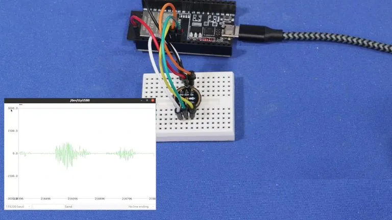
After that I read the values of the values of the sound by showing the values of variations in the serial monitor.
An input device is any hardware device that sends data to a computer, allowing you to interact with and control it.
The most commonly used or primary input devices on a computer are the keyboard and mouse.
However, there are dozens of other devices that can also be used to input data into the computer.
In this case, we are not talking about a computer, rather a microcontroller that processes data from the input device to produce the desired output.
Normally, there is an analog way of processing sound, by amplification, modulation (of necessary), mixing,...
But here i will use the microphone to generate sound that is going to be saved to the memory card, (as per my project design)
In the meantime, i will just be happy to be able to have the microcontroller read the input from the microphone and send the output to the speakers.
PLAN:
1. Using the board i designed for input devices' week, I will connect the microphone as an analog input.
2. I will tell the esp 32 to read the microphone's signal
3. Output the signal through the speakers
4. Analyse variations by displaying the input voltage levels on the serial monitor.
When i get to the final project stage, i will add a way to write a piece of sound on an SD card.
I2S Interface INMP441 is a microphone that uses I2S protocol. This is the one i will use for the final project as well.
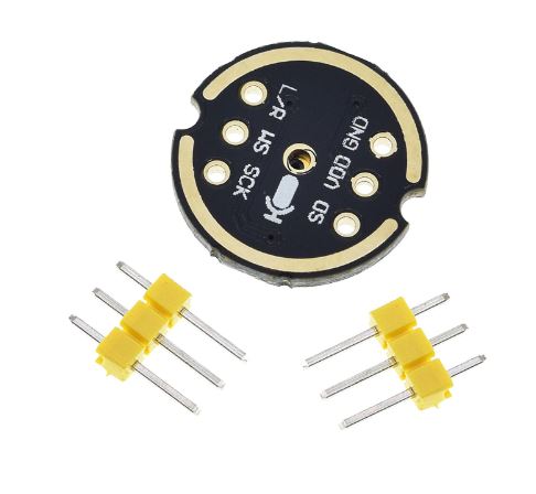 Description
The INMP441 is a high-performance, low power, digital-output, omnidirectional MEMS microphone with a bottom port. The INMP441 is available in a thin 4.72 x 3.76 x 1 mm surface mount package. It is reflow- solder compatible with no sensitivity degradation. The INMP441 is halide free. The INMP441 has a high signal-to-noise ratio and is an excellent choice for near field applications. The INMP441 has a flat wideband frequency response that results in high definition of natural sound.
Features:
1. Digital I2S interface with high precision 24-bit data
2. High signal to noise ratio is 61 dBA
3. High sensitivity – 26 dBFS
4. Stable frequency response from 60 Hz to 15 kHz
5. Low power consumption: low current consumption 1.4 mA
6. High PSR: -75 dBFS
Interface definition:
SCK: Serial data clock for I2S interface
WS: Serial data word selection for I2S interface
L/R: Left/Right channel selection.
When set to low, the microphone outputs a signal on the left channel of the I2S frame.
When set to high level, the microphone outputs signals on the right channel
SD: Serial data output of the I2S interface.
VCC: Input power, 1.8V to 3.3V.
GND: power ground
This product provides tutorials for using ESP32 modules with I2S functionality
Connect to ESP32:
INMP441 >> ESP32
SCK >> GPIO14
SD >> GPIO32
WS >> GPIO15
L/R >> GND
GND >> GND
VDD >> VDD3.3
What is the difference between an omnidirectional microphone and a unidirectional microphone:
First of all, I understand that the sound divergence is all-round. One person speaks and diverge in the air.
As for how far it can pass, it depends on many factors.
1.directional microphone, the general pickup radius is very small, 30 cm is a big one, single use, put it on the mouth, the sound quality is very good, because it is not picked up again.
The shape is generally goose neck wheat, a rod, a curved rod, to your mouth, directivity, just listen to your voice.
With a single-point microphone, the sensitivity is limited to a certain range. Sensitivity is too hig
INMP441 Microphone Module Hookup
Here is how we will be hooking up our microphone module and ESP32.
Hardware requirements
INMP441 Microphone Module
ESP32 Development Board
Connecting wires
Mini Micro USB Cable for ESP32
How is the Microphone connected to the SP32?
Description
The INMP441 is a high-performance, low power, digital-output, omnidirectional MEMS microphone with a bottom port. The INMP441 is available in a thin 4.72 x 3.76 x 1 mm surface mount package. It is reflow- solder compatible with no sensitivity degradation. The INMP441 is halide free. The INMP441 has a high signal-to-noise ratio and is an excellent choice for near field applications. The INMP441 has a flat wideband frequency response that results in high definition of natural sound.
Features:
1. Digital I2S interface with high precision 24-bit data
2. High signal to noise ratio is 61 dBA
3. High sensitivity – 26 dBFS
4. Stable frequency response from 60 Hz to 15 kHz
5. Low power consumption: low current consumption 1.4 mA
6. High PSR: -75 dBFS
Interface definition:
SCK: Serial data clock for I2S interface
WS: Serial data word selection for I2S interface
L/R: Left/Right channel selection.
When set to low, the microphone outputs a signal on the left channel of the I2S frame.
When set to high level, the microphone outputs signals on the right channel
SD: Serial data output of the I2S interface.
VCC: Input power, 1.8V to 3.3V.
GND: power ground
This product provides tutorials for using ESP32 modules with I2S functionality
Connect to ESP32:
INMP441 >> ESP32
SCK >> GPIO14
SD >> GPIO32
WS >> GPIO15
L/R >> GND
GND >> GND
VDD >> VDD3.3
What is the difference between an omnidirectional microphone and a unidirectional microphone:
First of all, I understand that the sound divergence is all-round. One person speaks and diverge in the air.
As for how far it can pass, it depends on many factors.
1.directional microphone, the general pickup radius is very small, 30 cm is a big one, single use, put it on the mouth, the sound quality is very good, because it is not picked up again.
The shape is generally goose neck wheat, a rod, a curved rod, to your mouth, directivity, just listen to your voice.
With a single-point microphone, the sensitivity is limited to a certain range. Sensitivity is too hig
INMP441 Microphone Module Hookup
Here is how we will be hooking up our microphone module and ESP32.
Hardware requirements
INMP441 Microphone Module
ESP32 Development Board
Connecting wires
Mini Micro USB Cable for ESP32
How is the Microphone connected to the SP32?
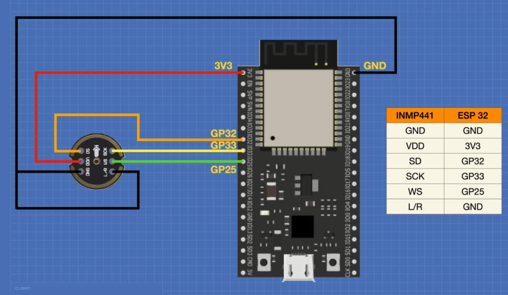 Note that your ESP32 may have a different pinout from the one illustrated here, use the GPIO numbers instead of physical pins to connect your module.
INMP441 Microphone Module Code
In our first experiment, we will be using the I2S Library that is installed in your Arduino IDE when you install the ESP32 Boards Manager files.
Here is what the code looks like:
/*
ESP32 I2S Microphone Sample
esp32-i2s-mic-sample.ino
Sample sound from I2S microphone, display on Serial Plotter
Requires INMP441 I2S microphone
Faranux Electronics
*/
// Include I2S driver
#include
// Connections to INMP441 I2S microphone
#define I2S_WS 25
#define I2S_SD 33
#define I2S_SCK 32
// Use I2S Processor 0
#define I2S_PORT I2S_NUM_0
// Define input buffer length
#define bufferLen 64
int16_t sBuffer[bufferLen];
void i2s_install() {
// Set up I2S Processor configuration
const i2s_config_t i2s_config = {
.mode = i2s_mode_t(I2S_MODE_MASTER | I2S_MODE_RX),
.sample_rate = 44100,
//.sample_rate = 11025, if you like
.bits_per_sample = i2s_bits_per_sample_t(16),
.channel_format = I2S_CHANNEL_FMT_ONLY_LEFT,
//.communication_format = i2s_comm_format_t(I2S_COMM_FORMAT_STAND_I2S),
.communication_format = i2s_comm_format_t(I2S_COMM_FORMAT_I2S | I2S_COMM_FORMAT_I2S_MSB),
.intr_alloc_flags = 0,
.dma_buf_count = 8,
.dma_buf_len = bufferLen,
.use_apll = false
};
i2s_driver_install(I2S_PORT, &i2s_config, 0, NULL);
}
void i2s_setpin() {
// Set I2S pin configuration
const i2s_pin_config_t pin_config = {
.bck_io_num = I2S_SCK,
.ws_io_num = I2S_WS,
.data_out_num = -1,
.data_in_num = I2S_SD
};
i2s_set_pin(I2S_PORT, &pin_config);
}
void setup() {
// Set up Serial Monitor
Serial.begin(115200);
Serial.println(" ");
delay(1000);
// Set up I2S
i2s_install();
i2s_setpin();
i2s_start(I2S_PORT);
delay(500);
}
void loop() {
// False print statements to "lock range" on serial plotter display
// Change rangelimit value to adjust "sensitivity"
int rangelimit = 3000;
Serial.print(rangelimit * -1);
Serial.print(" ");
Serial.print(rangelimit);
Serial.print(" ");
// Get I2S data and place in data buffer
size_t bytesIn = 0;
esp_err_t result = i2s_read(I2S_PORT, &sBuffer, bufferLen, &bytesIn, portMAX_DELAY);
if (result == ESP_OK)
{
// Read I2S data buffer
int16_t samples_read = bytesIn / 8;
if (samples_read > 0) {
float mean = 0;
for (int16_t i = 0; i < samples_read; ++i) {
mean += (sBuffer[i]);
}
// Average the data reading
mean /= samples_read;
// Print to serial plotter
Serial.println(mean);
}
}
}
Testing the Microphone
Hook everything up, load the sketch and open the Serial Plotter.
Note that your ESP32 may have a different pinout from the one illustrated here, use the GPIO numbers instead of physical pins to connect your module.
INMP441 Microphone Module Code
In our first experiment, we will be using the I2S Library that is installed in your Arduino IDE when you install the ESP32 Boards Manager files.
Here is what the code looks like:
/*
ESP32 I2S Microphone Sample
esp32-i2s-mic-sample.ino
Sample sound from I2S microphone, display on Serial Plotter
Requires INMP441 I2S microphone
Faranux Electronics
*/
// Include I2S driver
#include
// Connections to INMP441 I2S microphone
#define I2S_WS 25
#define I2S_SD 33
#define I2S_SCK 32
// Use I2S Processor 0
#define I2S_PORT I2S_NUM_0
// Define input buffer length
#define bufferLen 64
int16_t sBuffer[bufferLen];
void i2s_install() {
// Set up I2S Processor configuration
const i2s_config_t i2s_config = {
.mode = i2s_mode_t(I2S_MODE_MASTER | I2S_MODE_RX),
.sample_rate = 44100,
//.sample_rate = 11025, if you like
.bits_per_sample = i2s_bits_per_sample_t(16),
.channel_format = I2S_CHANNEL_FMT_ONLY_LEFT,
//.communication_format = i2s_comm_format_t(I2S_COMM_FORMAT_STAND_I2S),
.communication_format = i2s_comm_format_t(I2S_COMM_FORMAT_I2S | I2S_COMM_FORMAT_I2S_MSB),
.intr_alloc_flags = 0,
.dma_buf_count = 8,
.dma_buf_len = bufferLen,
.use_apll = false
};
i2s_driver_install(I2S_PORT, &i2s_config, 0, NULL);
}
void i2s_setpin() {
// Set I2S pin configuration
const i2s_pin_config_t pin_config = {
.bck_io_num = I2S_SCK,
.ws_io_num = I2S_WS,
.data_out_num = -1,
.data_in_num = I2S_SD
};
i2s_set_pin(I2S_PORT, &pin_config);
}
void setup() {
// Set up Serial Monitor
Serial.begin(115200);
Serial.println(" ");
delay(1000);
// Set up I2S
i2s_install();
i2s_setpin();
i2s_start(I2S_PORT);
delay(500);
}
void loop() {
// False print statements to "lock range" on serial plotter display
// Change rangelimit value to adjust "sensitivity"
int rangelimit = 3000;
Serial.print(rangelimit * -1);
Serial.print(" ");
Serial.print(rangelimit);
Serial.print(" ");
// Get I2S data and place in data buffer
size_t bytesIn = 0;
esp_err_t result = i2s_read(I2S_PORT, &sBuffer, bufferLen, &bytesIn, portMAX_DELAY);
if (result == ESP_OK)
{
// Read I2S data buffer
int16_t samples_read = bytesIn / 8;
if (samples_read > 0) {
float mean = 0;
for (int16_t i = 0; i < samples_read; ++i) {
mean += (sBuffer[i]);
}
// Average the data reading
mean /= samples_read;
// Print to serial plotter
Serial.println(mean);
}
}
}
Testing the Microphone
Hook everything up, load the sketch and open the Serial Plotter.