WEEK07 - Programmed Machining
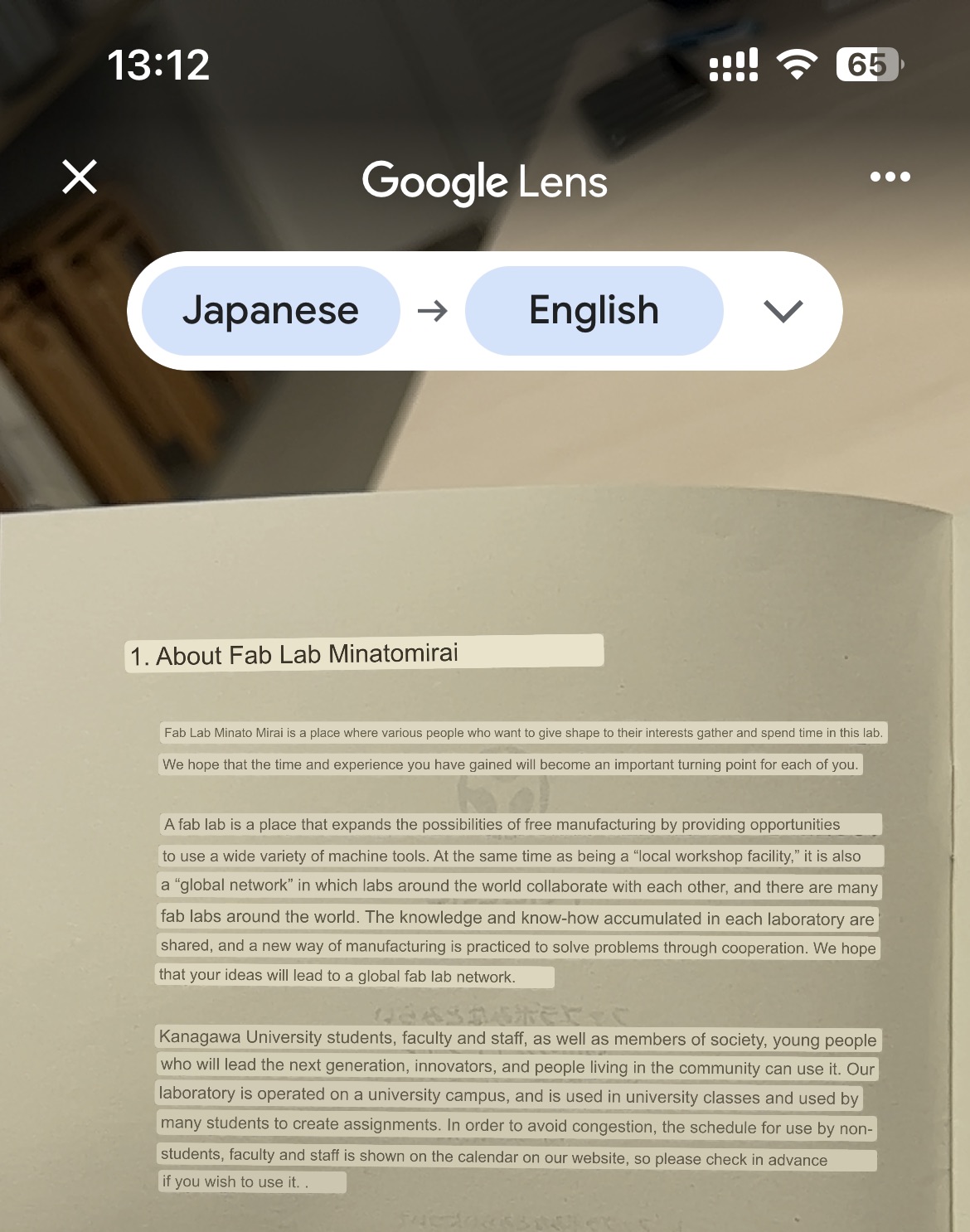
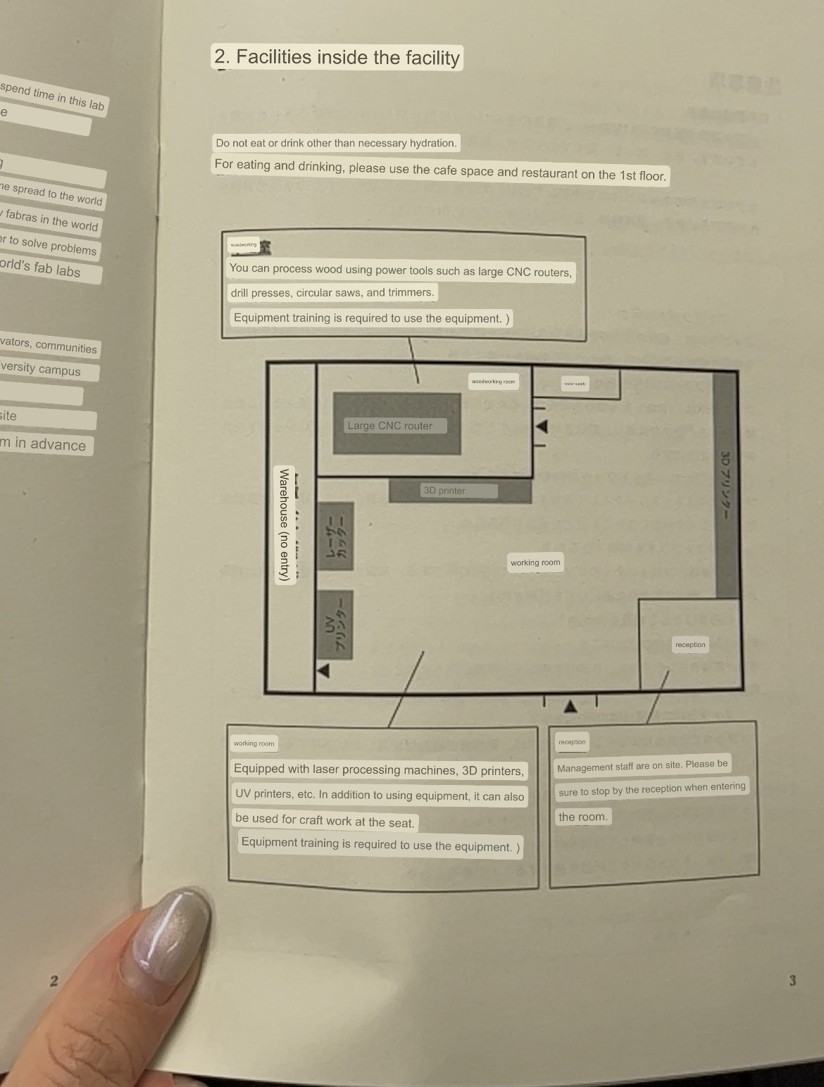
This week was machine programmed work . So we got to explore large CNC milling. Here in Kamakura we unfortunatly don't have our own large CNC machine, which is a shame in terms of experimentation but we got to visit the Fablab at the Minatomirai Campus of Kanagawa University.
WEEK SEVEN ASSIGNMENT
| Assignments | Completed |
|---|---|
| GROUP | |
| - do your lab's safety | |
| - training test runout, alignment, fixturing, speeds, feeds, materials, and toolpaths for your machine | GROUP ASSIGNMENT PAGE here |
| INDIVIDUAL | |
| - make (design+mill+assemble) something big (~meter-scale) | - done |
| - extra credit: don't use fasteners or glue | - done |
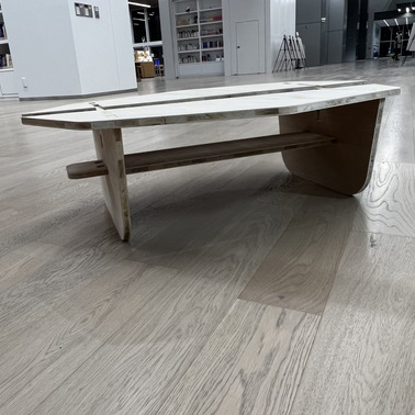
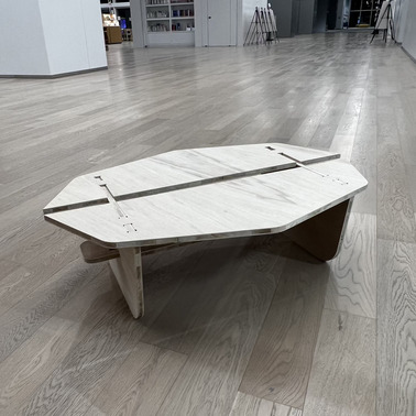
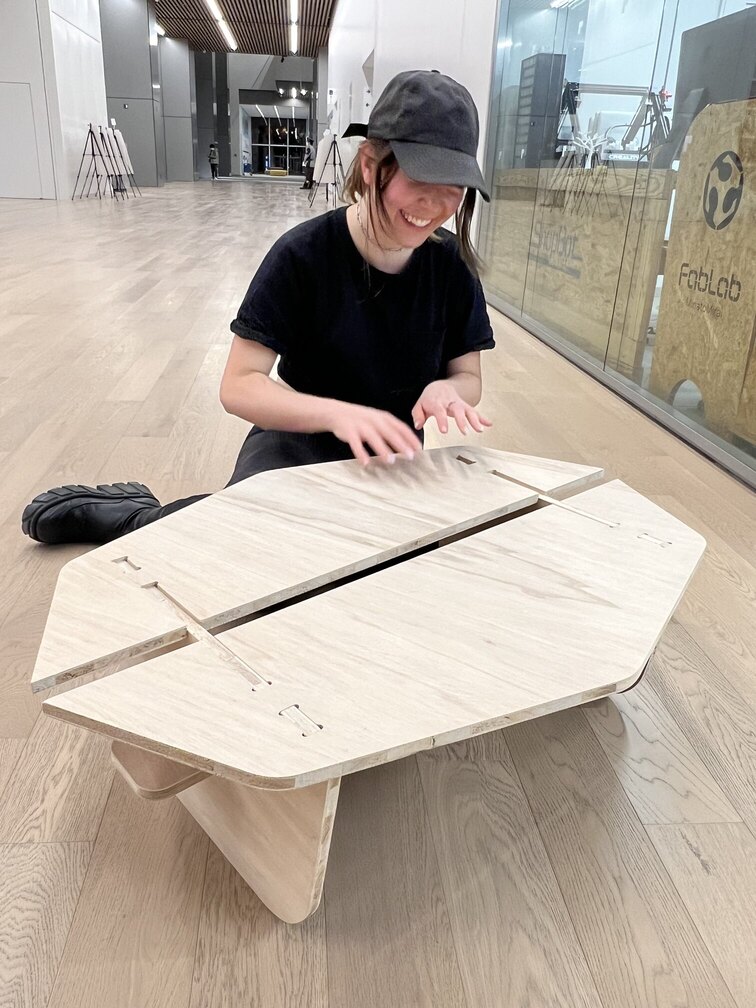
HERO-SHOTS
GROUP ASSIGNMENT
We started the day with our group assignment, this mean classifying and figuring out the design characteristics of both our wood and the machine that we were using. You can find this here.
KEY LESSONS: Double check everything.
MACHINE SPECS:
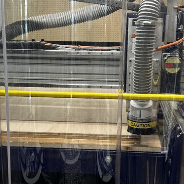
At MinatomiRai the following CNC Machine is in use:
The Assembly-guide and manual can be found -> here
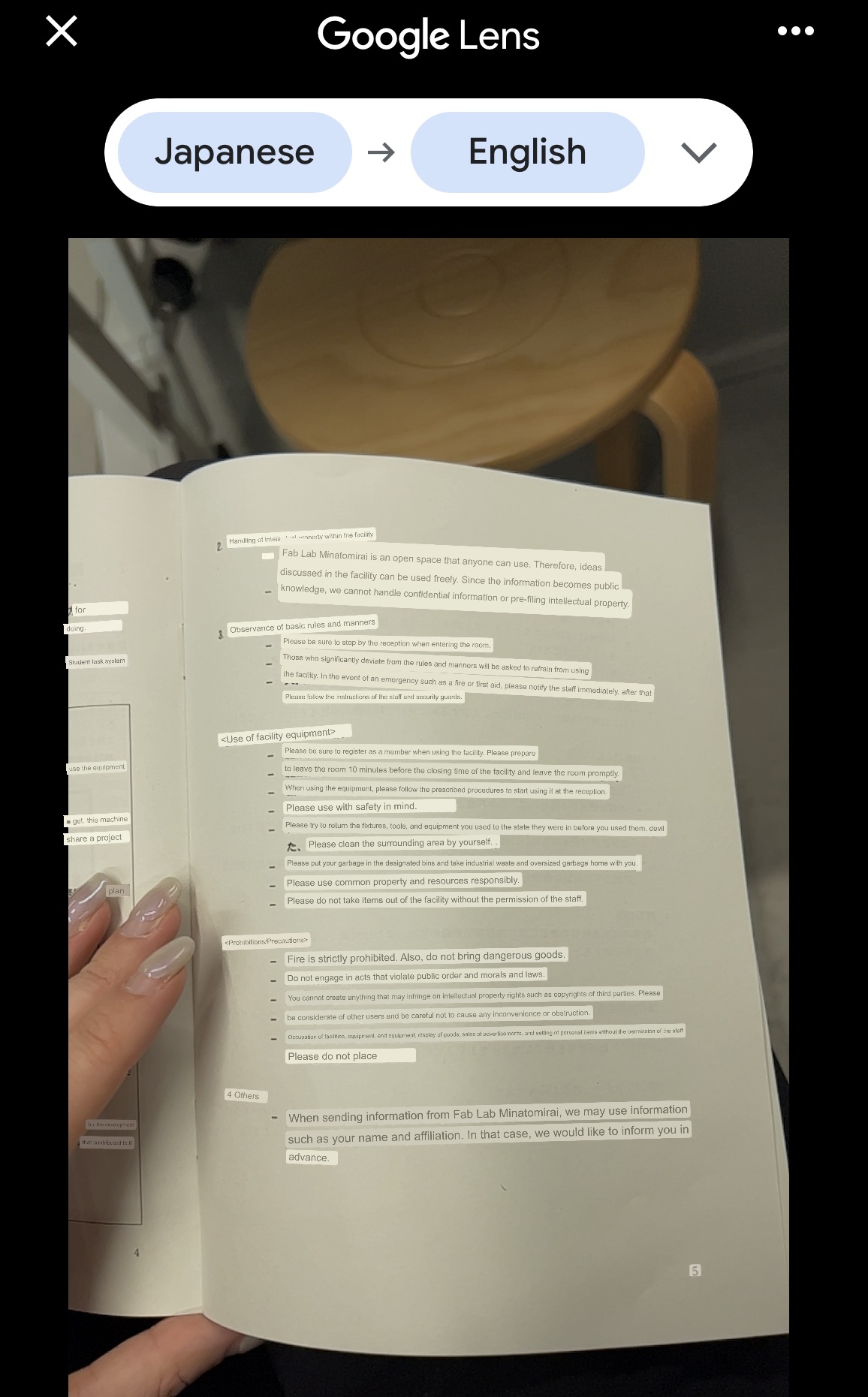
Since this is a university lab the safety rules and interactions with the machine are more strict than other fablabs, and we had to do a seperate safety lecture for the lab itself other than just for the CNC.
The overall safety rules are in-place: No open shoes No loose hair No loose clothing Be alert etc
Before ever touching the machine we had to go through the Lab-safety lecture... though it was in japanese....
Additionally the machine is set up with certain safety-measures in place which were tied to how the machine is set up: for example the wrench is linked directly to the key so it is physically impossible to attempt to change anything on the machine while the key is still plugged in.
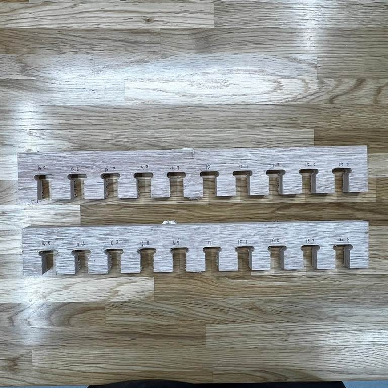
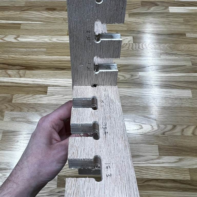
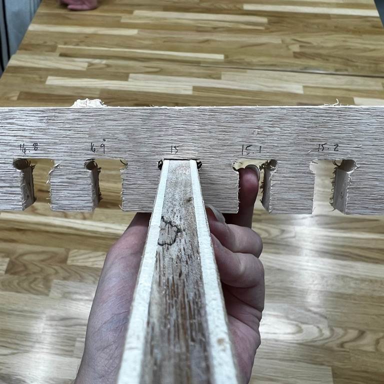
KERF TESTS
More details on this can be found on our group page, but following the safety demonstrations we also did Kerf tests.
We generated the Kerf SVG test file for use with 15mm thick plywood using the Kerf Check Parts Generator
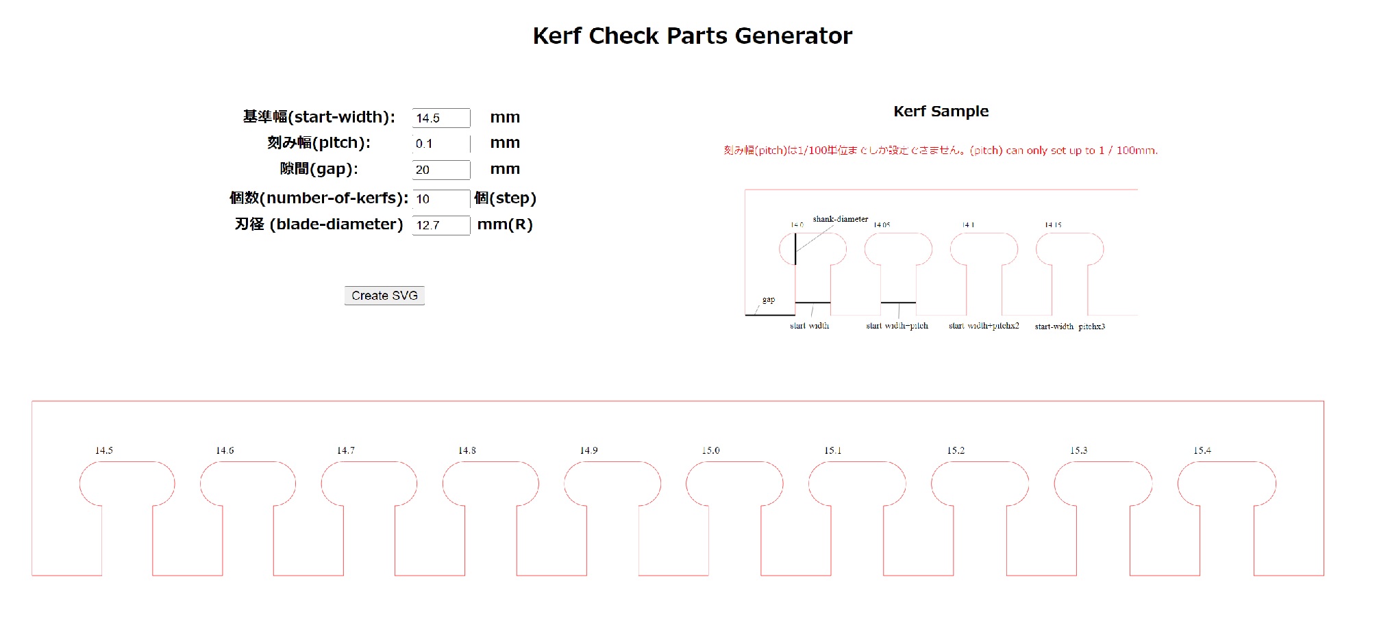
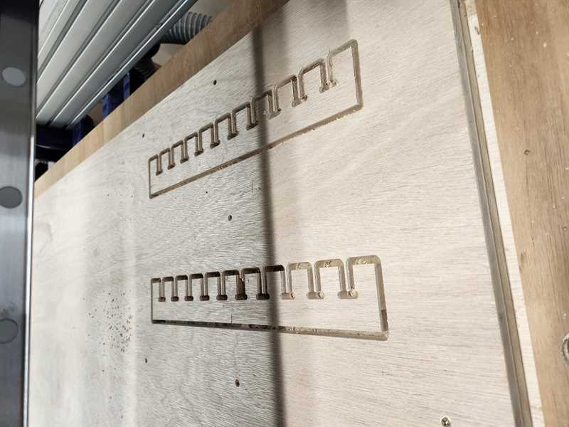
We found that 15 fit well together.
CHOOSING A DESIGN
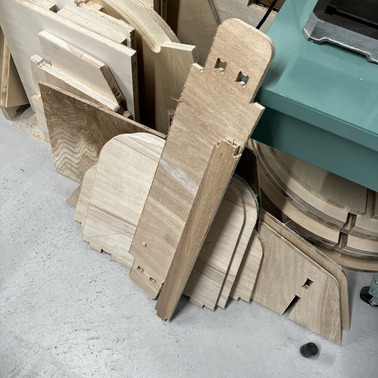
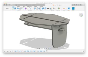
For this week, I decided to be a little more practical. Also in part due to the limited time we have with CNC milling here in Kamakura. So for the sake of this week I decided to do a slightly modular living-room table.
I just moved into a new apartment and I don't have very much furniture yet. So I just went for something that I really needed. I added a modular element by also designing a pair of legs in a different height. This way, if I ever decide that I don't need the table anymore, I can turn it into a bench.
WISHES AND THOUGHTS
I really wish I could have made this week assignment out of Acrylic, as I think I would have enjoyed the final product a lot more.
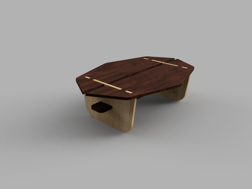
3D DESIGN
The wood that was provided was a 15 x 910 x 1820 mm, so all the pieces had to fit into that.
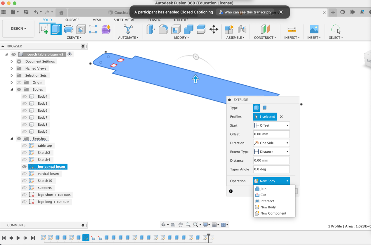
I went into fusion to design the table. I am slowly getting used to Fusion360, and modeling it parametically did help in creating the schematics, also I found that modeling in reverse is also some times a good idea.
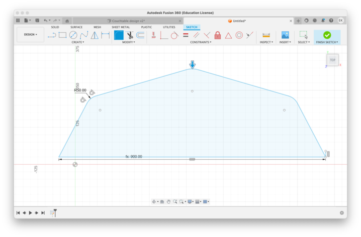
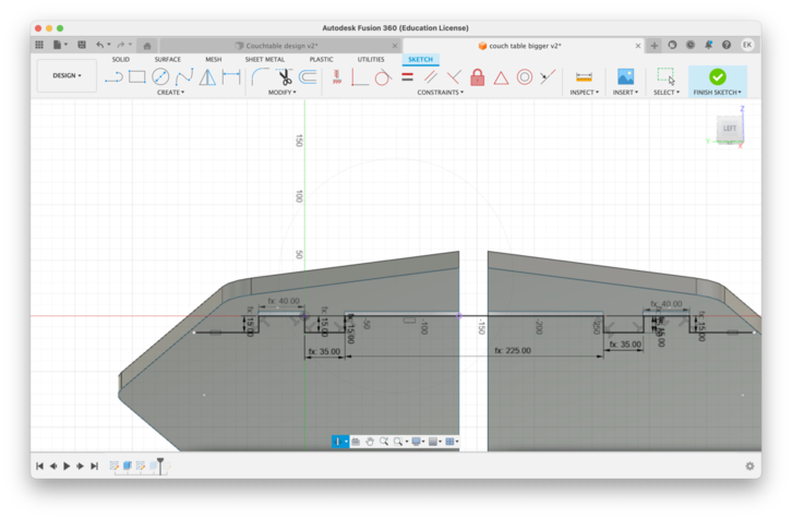
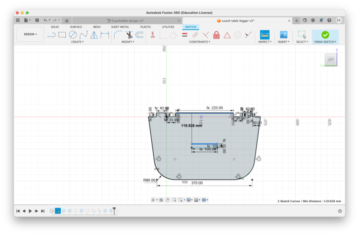
So to ensure that the insertion holes for the lower shelves we're in the right places I actually extruded the sketches as 'cut' - so that the extrusion itself would create the schematic. and then I exported the body back into the sketch field and then as dxf.
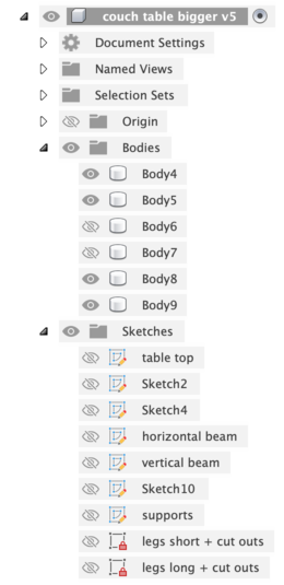
but i have since been told that there could have been a better way.
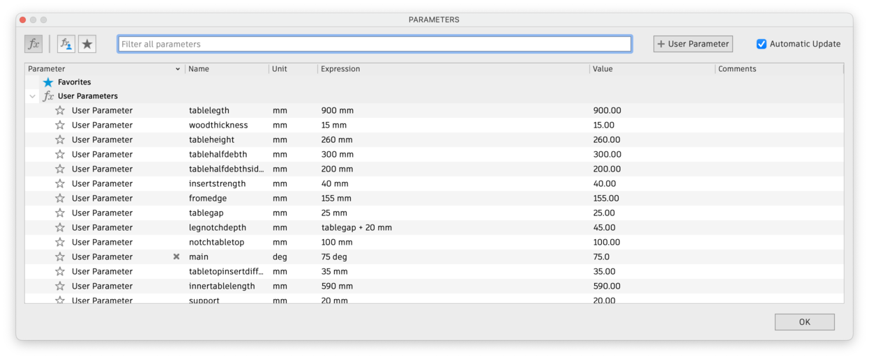
These were my parameters.
PREPPING THE FILES
So in the case of working with CNC for furniture design, just designing the schematic really isn't enough.
There are two parts of the additional design process that are important for CNC: - adding the location of the screw holes - adding fillets + tabs.
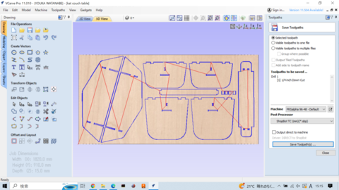
I did this using VCARVE. I also did the arrangement of my parts in V-carve.
You save two tool paths: 1. Drill ( for the holes) 2. Trace ( the cut-outs)
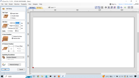
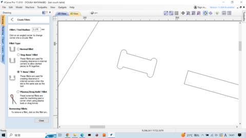
VCARVE
Open Vcarve -> set the parameters of your material
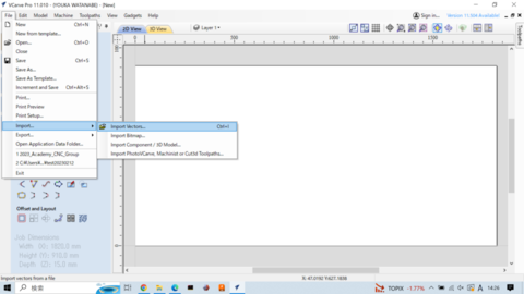
Import
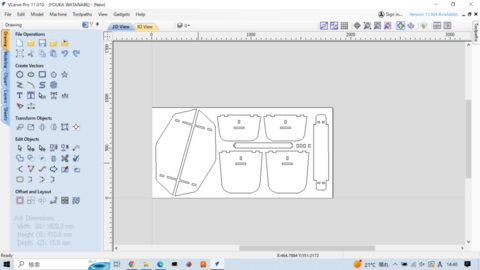
Arrange
Add Fillets: These are added to INTERNAL corners ! ( because the drill bit is round)
After this I used Vcarve to to place drill holes in the material, in places which were no where close to the traces of my design.
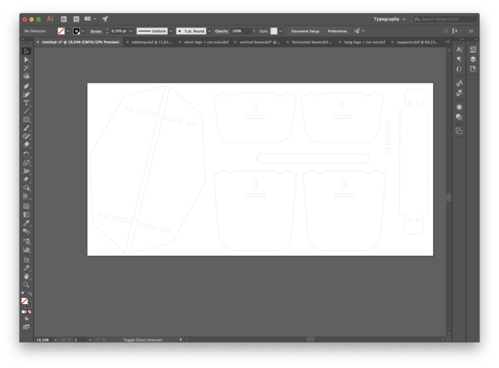
THE TRACES
These are the trace files that I exported from Vcarve. I have one file for the trace and one file for the drill path.
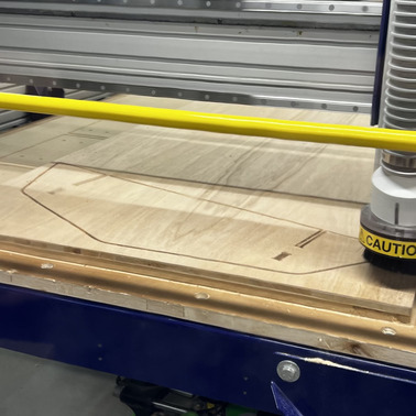
THE MILLING
I followed the instructions that we received during the group assignment.
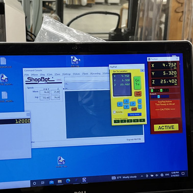
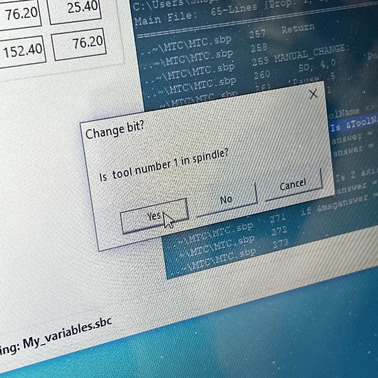
I used the drill-path file first to pre-drill the placements for the nails to make sure the material cannot move. Doing it this way also ensures that the drill bit should never hit the nails.
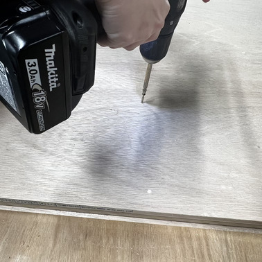
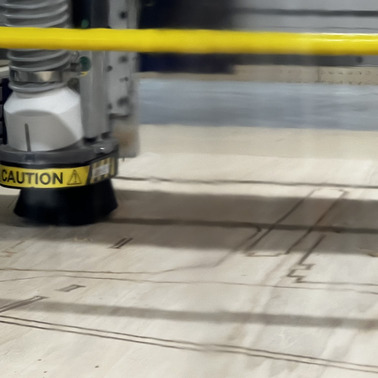
And then I watched the machine cut.