WEEK04 - Embedded Programming
This week was exploring microchips, development environments and programming. I played around with various environments in the group assignment and in the personal assignment I explored the Arduino UNO architecture - through the GROVE BEGINNER KIT from Seed Studio.
For the group assignment we were asked to compare different microcontrollers, chips and architectures. You can find this here.
WEEK FOUR ASSIGNMENT
| Assignments | Completed |
|---|---|
| GROUP | |
| - compare the performance and development workflows for other architectures. | GROUP ASSIGNMENT PAGE here |
| INDIVIDUAL | |
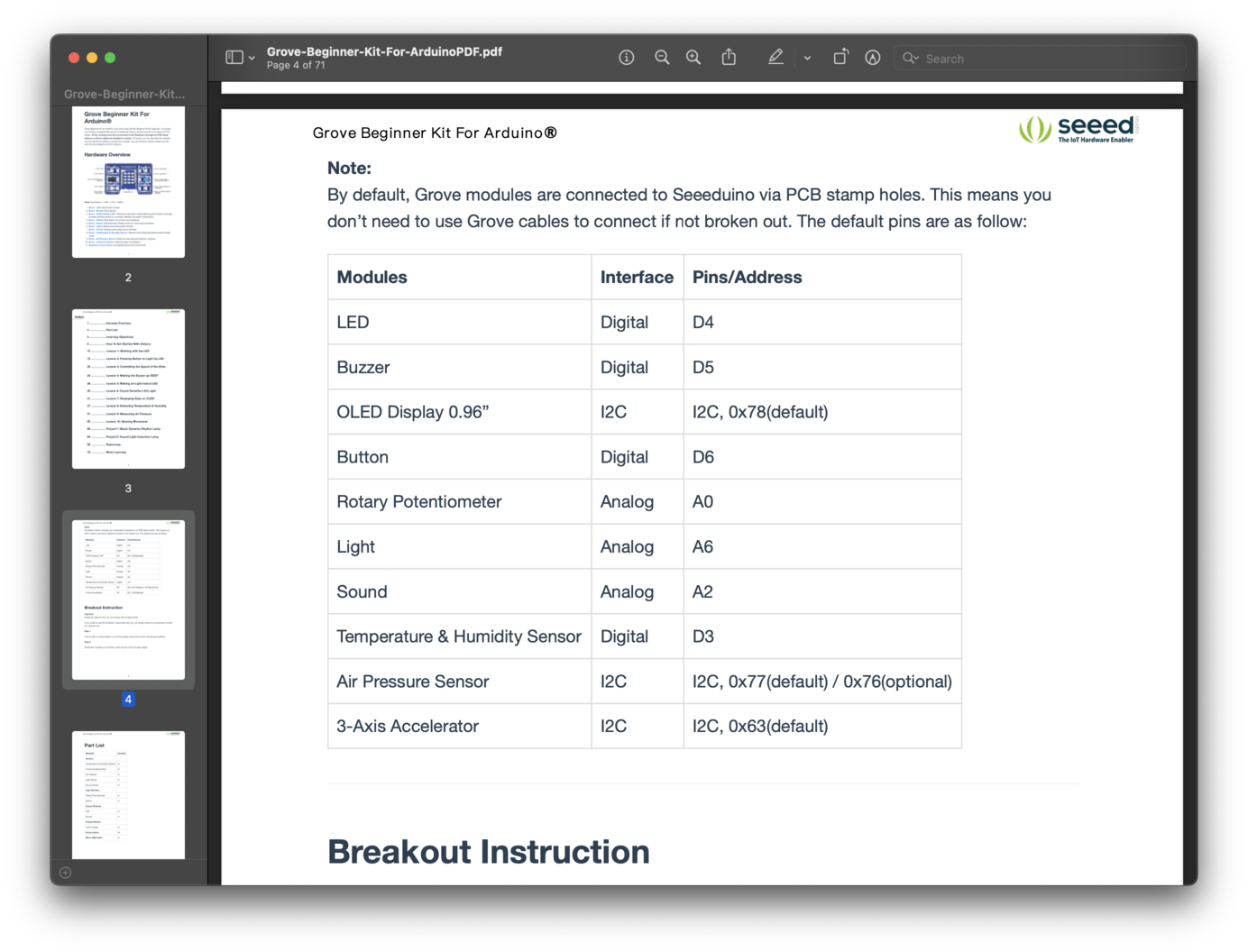
| - browse through the data sheet for your microcontroller | - read to the datasheet and instructions PDF for Seeduino and Grove Kit. |
| - program a microcontroller development board to interact (with local input &/or output) and communicate (remotely) | - programmed the Seeduino-board to interact with Air-pressure sensor and OLED display to measure airpressure. |
| - extra credit: use different languages &/or development environments |
HERO-SHOTS
Grove Beginner Kit For Arduino®
This beginner kit has a Arduino Uno compatible board and 10 additional sensors. Since for my final project I am looking to primarily experiment with various sensors and sensing devices that measure and re-display changes in the environment the Grove kit seemed like a good place to start to begin with.
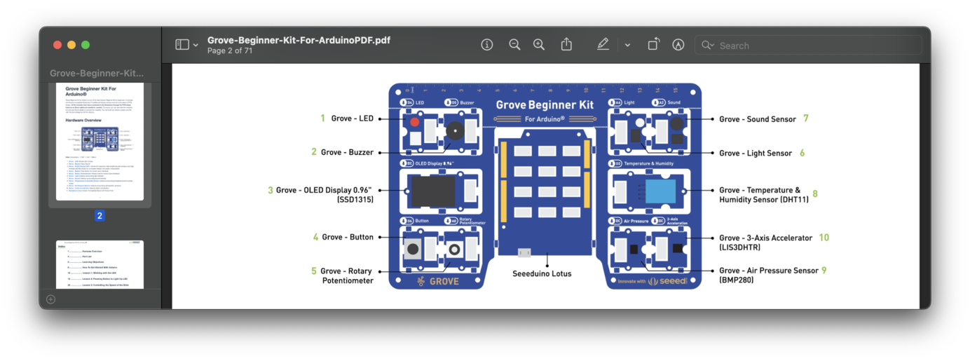
The first thing I did was look and work my way through the accompanying PDF. I would highly advise this as the PDF is really good at breaking down each sensor and extension and at explaining what is happening to make the code work. They also provide you with example code.
Historize, Historize
Some background info about the Arduino Uno: It's an opensource microcontroller board based on the Microchip ATmega328P. It should be noted that it was originally released in 2010, so its currently at the time of this document 13 years old. There are much faster chips available today, and something I will definitely be trying later is to transfer the program I made using the teaching-PDF to other chips, to see how the performance might improve or change.
DATA-SHEET
As mentioned above, the Grove kit features a ATmega328P. So I browsed the data sheet and gathered the following info:
What is the name of the microcontroller (MCU)? The microcontroller is called ATmega328P.
What type of 'architecture' is it? The MCU has an 8-bit AVR RISC architecture.
What is its Clock Speed? The MCU has a maximum clock speed of 20 MHz.
What different types of memory does it have? How much of each? The MCU has 32 KB of In-System Self-Programmable Flash memory, 1 KB of EEPROM memory, and 2 KB of SRAM.
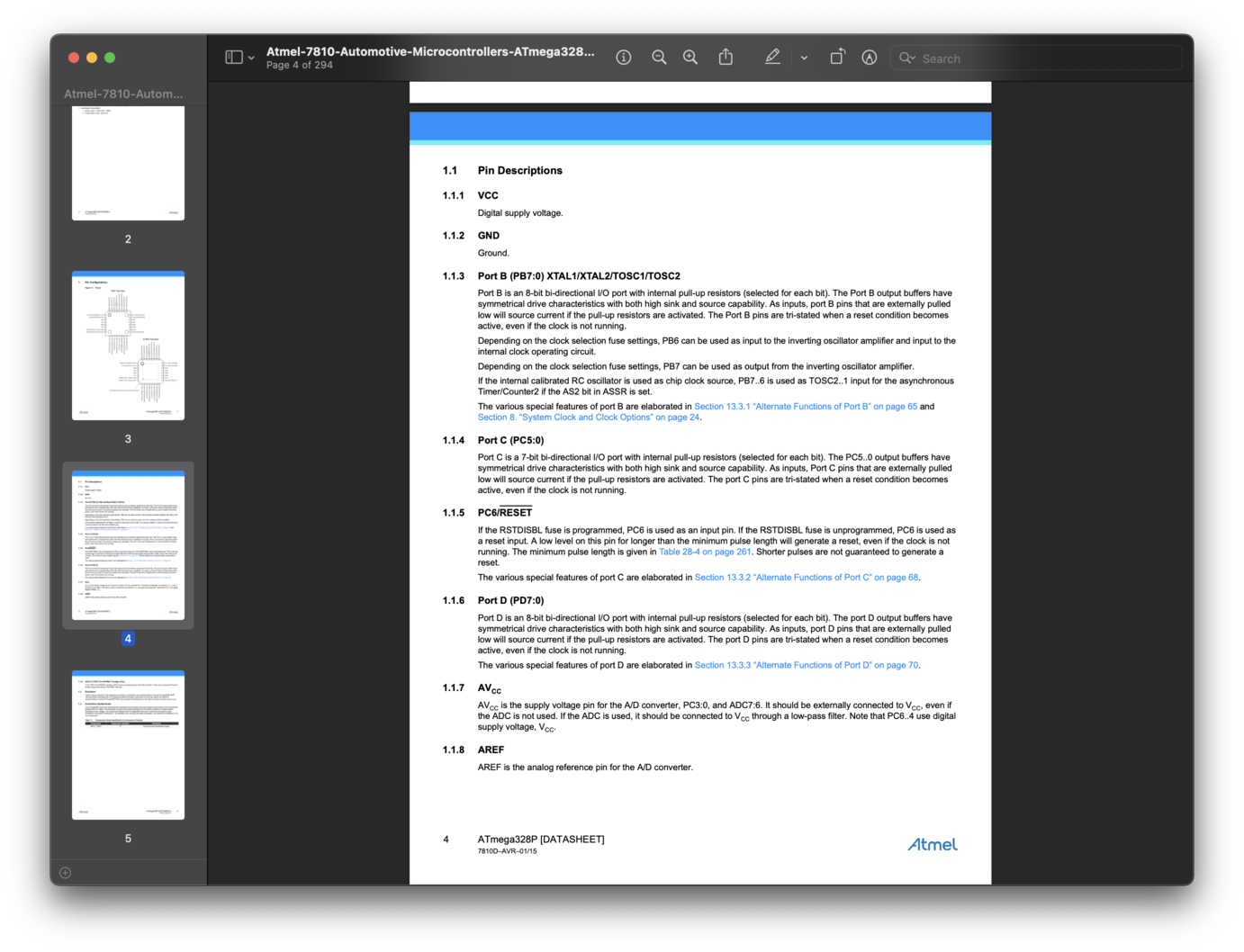
How many pins does the MCU have? The MCU has 28 pins in total.
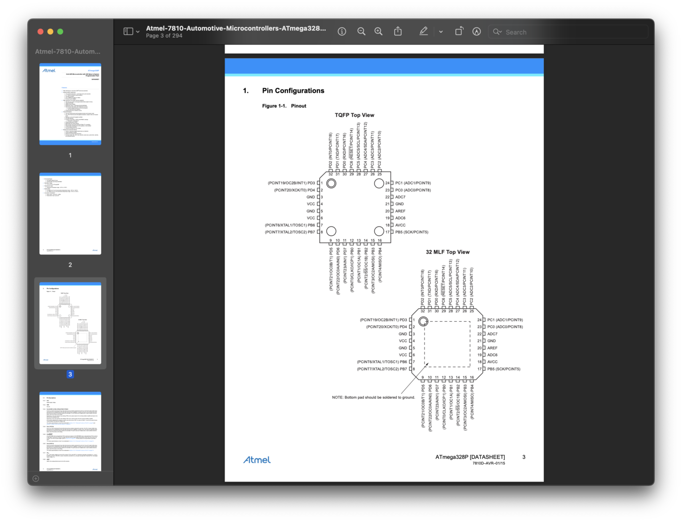
How many GPIO pins? All 28 pins can be used as GPIO pins.
How many Digital pins? What are their pin numbers? All 28 pins can be used as digital pins, and they are labeled D0 through D27.
How many Analog pins? What are their pin numbers? The MCU has 6 analog input pins, labeled A0 through A5.
How many pins capable of PWM? The MCU has 6 pins capable of PWM output, which are also the same pins as the 6 analog input pins (A0-A5).
What types of Communication Protocol can the MCU do (ISP, UPDI, Serial, etc.)? The MCU supports several communication protocols including UART, SPI, and I2C. It also supports In-System Programming (ISP) and can be programmed using the SPI interface.
What (fancy) extra features..."hardware peripherals" does the MCU have (DAC, ADC, etc)? The MCU has several hardware peripherals, including a 10-bit Analog-to-Digital Converter (ADC) with up to 8 channels, a programmable Watchdog Timer, a Real-Time Counter with a separate oscillator, and a variety of timers and interrupts. It also has a built-in temperature sensor and a programmable Serial USART for communication with external devices.
COMPARISONS
For the sake of understanding how the different MCU's relate to each other I made a little break-down here. Also to gather which one might be better suited for my final project. Since my final project is portable I need a chip that is feasible to run off portable batteries; remains small in size to create sleek wearables and still feature enough memory that is capable of running code
| Parameters | ATmega328P | XIAO SAMD21 | XIAO ESP32 |
|---|---|---|---|
CPU TYPE |
8-bit AVR | 32-bit | 32-bit |
Architecture |
RISC | ARM Cortex-M0 | RISC-V |
Performance |
20 MIPS at 20 MHz | 48MHz | 160 MHz |
Maximum CPU speed |
20 MHz | 48MHz | 160 MHz |
FLASH MEMORY |
32 KB | 256KB | 4MB |
SRAM |
2 KB | 32KB | 400KB |
EEPROM |
1 KB | ||
Package pin count |
28 or 32 | 14 GPIO PINs | |
Maximum I/O pins |
23 | 11 analog, 11 digital | 11pmw/4analog |
Voltage |
2.7V - 5.5V | 3.3V/5V DC | 5V |
WIFI |
no | no | yes |
I think based on this comparison for my project I will try to run the wearable sensors from the SAMD21 chip, since it needs less energy, however the wifi and bluetooth capabilities of the ESP32 might proof useful for datacollection and storage or maybe even to externally communicate with the display output... So if I can find a sustainable portable powersolution which fits the casing this might be the way to go.
Step 1: Install Arduino IDE
Arduino IDE is an integrated development environment for Arduino, which is used for single- chip microcomputer software programming, downloading, testing and so on. Download and Install Arduino IDE for your desired operating system here.
Step 2: Install USB drivers
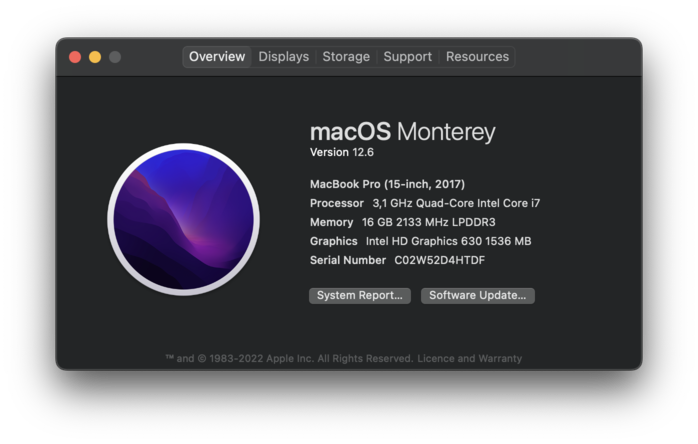
Arduino connects to the PC via a USB cable. The USB driver depends on the type of USB chip you’re using on your Arduino. Note: USB chips are usually printed on the back of the development board. For Mac OS users: You can navigate to on the top left corner, and choose About this Mac -> System Report... -> USB . A CP2102 USB Driver should appear. If the driver is not installed, or if the driver is installed incorrectly (not matching the chip model), it will appear as an “unknown device” in the device manager. At this point, the driver should be reinstalled.
For this week I installed the drivers for: ATmega328P --> here
For the XIAO SAMD21 and XIAO ESP32 I added the board to Arduino IDE this way:
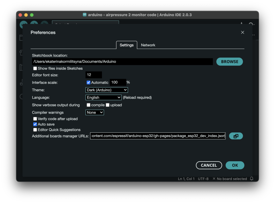
Navigate to File > Preferences, and fill "Additional Boards Manager URLs" with the url below:
XIAO SAMD21 --> https://files.seeedstudio.com/arduino/package_seeeduino_boards_index.json
XIAO ESP32 --> https://raw.githubusercontent.com/espressif/arduino-esp32/gh-pages/package_esp32_dev_index.json
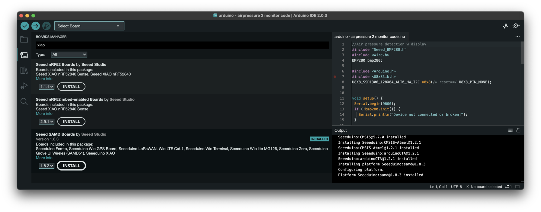
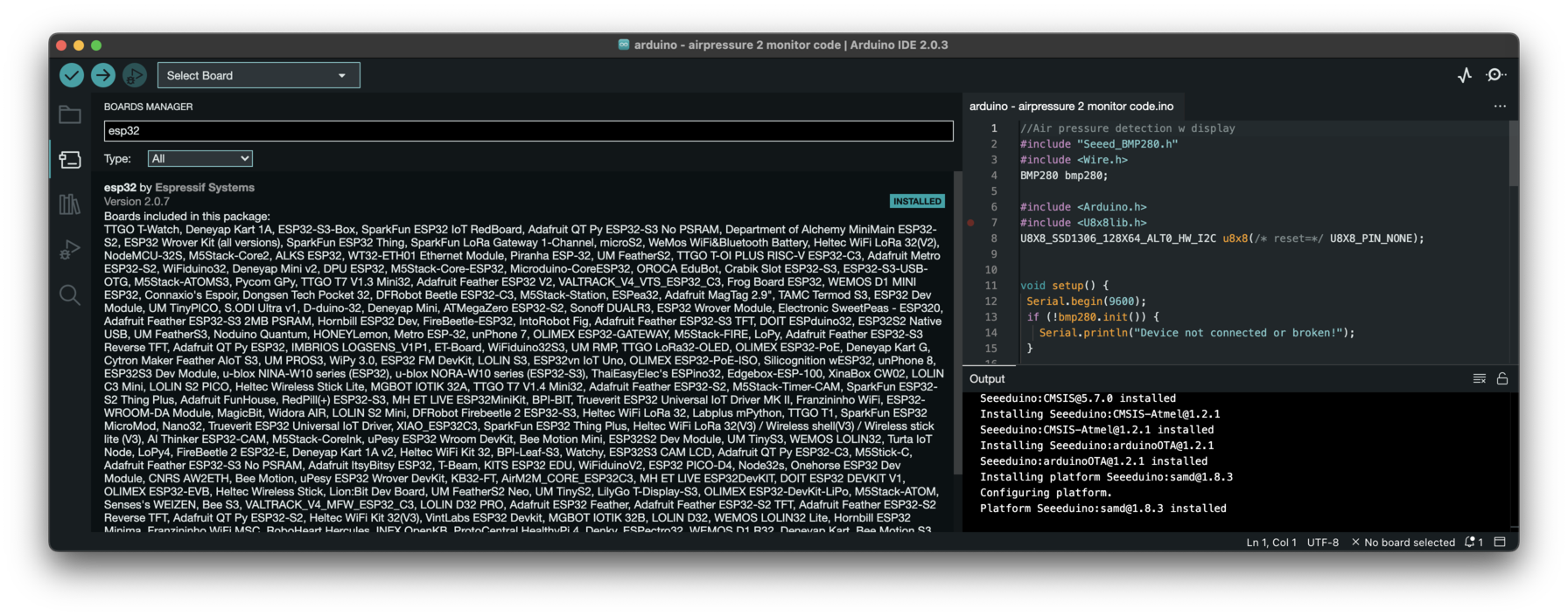
NEXT: Click Tools-> Board-> Boards Manager..., print keyword "Seeed Studio XIAO SAMD21 " or "ESP32" in the searching blank. Here comes the "Seeed SAMD Boards". Install it.
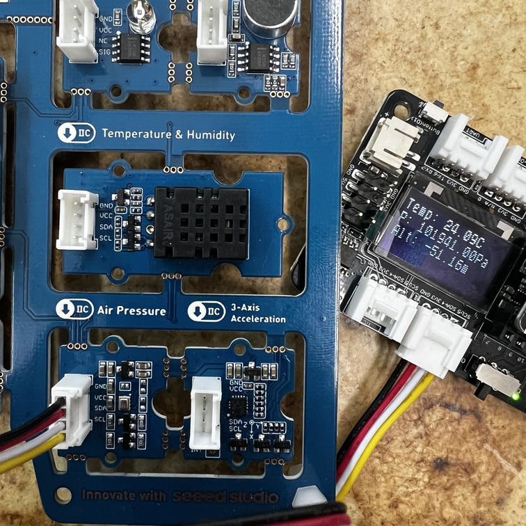
Let's Begin: Air-pressure Sensor + Display
So to begin understanding the Arduino Uno Architecture, I decided to try and combine two tutorials from the entry PDF. The Kit introduces us to the LED screen - something I definitely want to incorporate in my Final Project as well as many other sensors. The other sensor I will play with today is the Airpressure sensor, as it is one of the included sensors which measure the environment.
Libraries needed:
- Install the Grove Barometer Sensor library: Navigate to Sketch -> Include Library -> Manage Libraries... and Search for the keyword “Grove BMP280” in the Library Manager, then install.
- Install the U8g2 library: Navigate to Sketch -> Include Library -> Manage Libraries... and Search for the keyword “U8g2” in the Library Manager, then install.
FINISHED CODE:
The code I used to was a combination of the Airpressure code, as well as the display data to the OLED Screen code. This was the final frankenstein:
Please don't forget to check for syntax errors.
 //Air pressure detection w display
 #include "Seeed_BMP280.h"
 #include <Wire.h>
 BMP280 bmp280;

 #include <Arduino.h>
 #include <U8x8lib.h>
U8X8_SSD1306_128X64_ALT0_HW_I2C u8x8(/* reset=*/ U8X8_PIN_NONE);

void setup() {
 Serial.begin(9600);
 if (!bmp280.init()) {
   Serial.println("Device not connected or broken!");
 }

 u8x8.begin();
 u8x8.setFlipMode(1);

}
void loop() {
 float pressure = bmp280.getPressure();
 float temp = bmp280.getTemperature();
 float altitude = bmp280.calcAltitude(pressure);

 String output = "Temp: " + String(temp) + "C\n";
 output += "P: " + String(pressure) + "Pa\n";
 output += "Alt: " + String(altitude) + "m\n\n";

 //get and print temperatures
 /*
    Serial.print("Temp: ");
    Serial.print(temp);
    Serial.println("C"); // The unit for  Celsius because original arduino don't support speical symbols
    //get and print atmospheric pressure data
    Serial.print("Pressure: ");
    Serial.print(pressure);
    Serial.println("Pa");
    //get and print altitude data
    Serial.print("Altitude: ");
    Serial.print(altitude);
    Serial.println("m");
    Serial.println("\n");//add a line between output of different times.

 */
 Serial.print(output);

 u8x8.setFont(u8x8_font_chroma48medium8_r);
 u8x8.setCursor(0, 0);
 u8x8.print(output);

 delay(1000);
}
Getting the code to work on the serial monitor internal to the Arduino IDE was easy. There it worked immediately. (just as the pdf promised), getting to also be displayed on the OLED monitor required a little bit of tinkering.
I had to define the output parameters, and create a string output.The original code has the output data be send to the serial monitor, but I wanted it to be send to both.
So instead of sending each individual output to the monitor as the original code had it, I blocked that bit of code out, and instead defined an output.
 String output = "Temp: " + String(temp) + "C\n";
 output += "P: " + String(pressure) + "Pa\n";
 output += "Alt: " + String(altitude) + "m\n\n";
And later on I told both monitors to display 'output'
 Serial.print(output);

 u8x8.setFont(u8x8_font_chroma48medium8_r);
 u8x8.setCursor(0, 0);
 u8x8.print(output);
The fun part about playing with Airpressure sensors is that it still tells you the temperature and other external sensing information, and you can alter that information by touching the sensors.... there is something that really fascinates me in how technology senses nature and how those links can be disrupted... it makes me think of how we define truth and reality and how these parameters are subjective.... even for machines.
ADDITIONAL INFORMATION reg. PROGRAMMING
Here are some syntax and structure tips and info's: Your programming sheet works top to bottom, so you start by defining the enviroment parameters: In this case this means that I need to make reference to the extentions required for the sensors and the screens:
  #include "Seeed_BMP280.h"
  #include <Wire.h>
  BMP280 bmp280;

  #include <Arduino.h>
  #include <U8x8lib.h>
 U8X8_SSD1306_128X64_ALT0_HW_I2C u8x8(/* reset=*/ U8X8_PIN_NONE);
After this you add your set-up syntax... and afterwards your loops. The loops are the bits of code which are to run repeatedly.. so this case I want there to be constant loop of the sensor readings as well, but I also want to follow the information in real-time on my monitors. That's why the loop includes the output lines
OTHER ARCHITECTURES AND TRANSFERS
To see how this transfers to other chips I decided to run the same code through the XIAO SAMD21 using the Seed Studio XIAO expansion board. The expansion-board already has a OLED screen build in - so I only had to connect the Air-Pressure sensor and voila: it still worked and still gave me an accurate pressure and temp reading.