WEEK05 - 3D scanning and printing
This week was dedicated to 3D printing and scanning. The aim was to understand the functionality of the 3D printing process, where it has it's advantages and disadvantages. First we characterized the printer at the Kamakura Lab, then I scanned basically anything I could get my hands on; using my phone to see what kind of things would glitch out. I had had some minor experiences with 3D printing, so what I wanted to explore most this week were the mistakes of 3D printers, and how to possibly take advantage of them adn design object with them in mind.
WEEK FIVE ASSIGNMENT
| Assignments | Completed |
|---|---|
| GROUP | |
| - test the design rules for your 3D printer(s) | GROUP ASSIGNMENT PAGE here |
| INDIVIDUAL | |
| - design and 3D print an object (small, few cm3, limited by printer time) that could not be made subtractively | - made an object in which the machine malfunctions discovered during the group assignment are a part of the design parameters!. |
| - 3D scan an object (and optionally print it) | - I tested many different 3D scanning softwares |
HERO-SHOTS
Understanding the 3D printer
The 3D printer I have for the duration of this course is the AnyCubic i3 s Mega. For the characterization of the FabLab Kamakura's 3D printers, I printed the All-in-One Object from Kickstarter-Autodesk-3d.
This test geometry is testing the following, all with one object:
Dimensional accuracy (backlash optional) Negative feature resolution Positive feature resolution/fine flow control Basic overhang capabilities Basic bridging capabilities XY ringing Z-axis alignment you can find the test object as well as the instructions on how to use it to characterize the printer here: https://github.com/kickstarter/kickstarter-autodesk-3d/blob/master/FDM-protocol/ksr_fdmtest_v4.stl
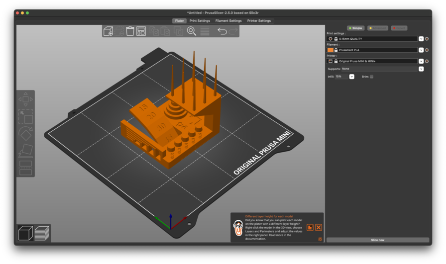
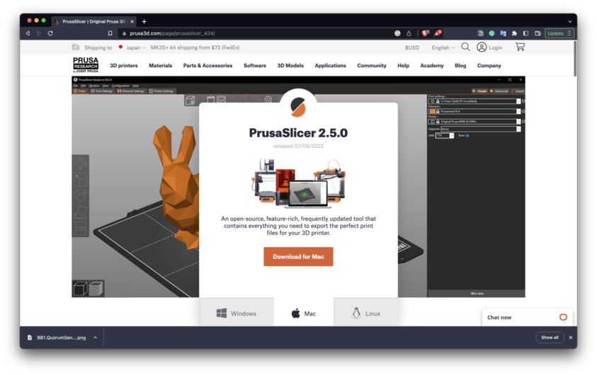
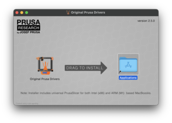
I also downloaded Prusa-Slicer to deal with the slicing:
Before starting I also cleaned the printer a little, and as a little reminder to myself: Youka-san reminded me to not use alcohol to clean the printer-bed as it has a film on it to help with the removal of the printed objects: It's better to clean it with just a mildly damp cloth.
Let's goooo: Dimensional Accuracy: To assess dimensional accuracy, measure each tier of the dimensional accuracy stack and record the absolute different between the target and the measured dimensions in a table like so:
| Target | measured x | measured y | x error | y error |
|---|---|---|---|---|
| `25 | 24.99 | 24,90 | 0,01 | 0,10 |
20 |
19.85 | 20,80 | 0,15 | 0,20 |
15 |
14,89 | 14, 85 | 0,11 | 0,11 |
10 |
9,75 | 9,80 | 0,25 | 0,20 |
5 |
4,85 | 4,90 | 0,15 | 0,10 |
Avg err: |
0,134 | 0,142 | ||
Average of avg. X and avg. Y error |
0,138 | |||
Difference between avg. X and avg. Y error |
0,008 |
Rating: 5
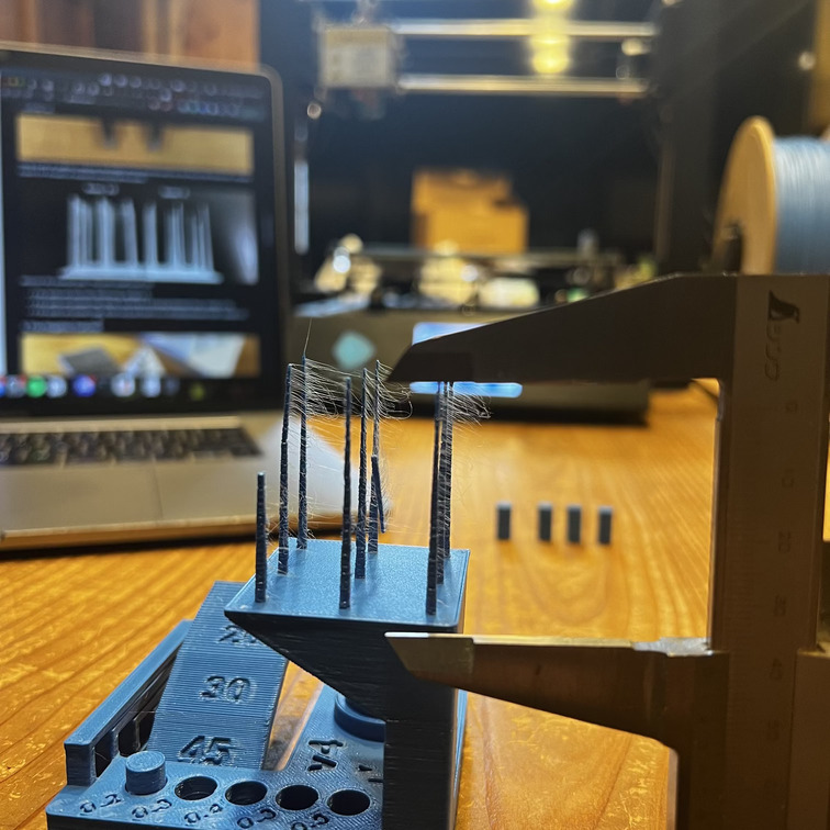
Fine FLow Control: Measure the shortest spire. This print would score 2.5. - If the spires are less than 30mm long, assign a 0. - If the spires are greater than 30mm, but there is stringing between them, assign a 2.5. - If the spires are greater than 30mm long and there is no stringing between them, assign a 5.
The spires are 3.7cm but there is string. Also .. I accidentally broke one.
Rating: 2.5
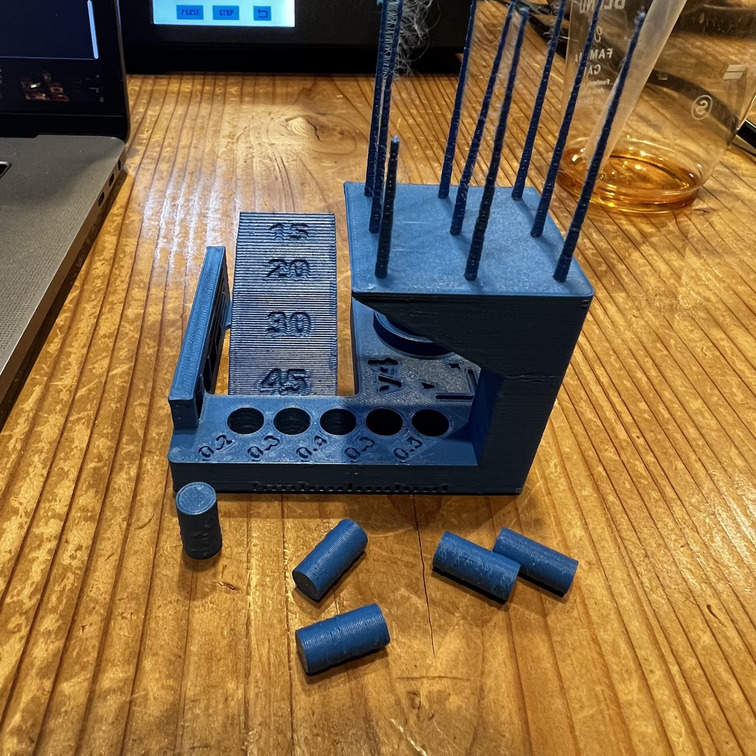
Fine Negative Features *Attempt to remove all the pins from their holes using fingers (no tools). The example above would score 2.
Record a “0” if no pins can be removed. Record a “1” if 1 pin can be removed. Record a “2” if 2 pins can be removed. Record a “3” if 3 pins can be removed. Record a “4” if 4 pins can be removed. Record a “5” if all pins can be removed.*
4 Pins removed easily. The fifth pin required some pressure, but I still removed it using only my fingers --> so I gave it a 4.5.
Rating: 4.5
Overhangs: Record a “1” if the printer compiled the geometry but dropped loops and infill on the 15, 20, and 30 degree overhangs. Record a “3” if only the 15 and 20 degree surfaces differ from the 45 degree overhang. Record a “4” if only the 15 degree overhang differs from the 45 degree overhang. Record a “5” if there the surface finish between all four overhang surfaces is equivalent.
Rating : 3
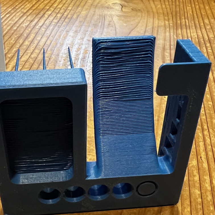
Bridging: *Inspect for contact between bridges and the surface beneath each. Record a “1” if more than 3 are in contact with the surfaces beneath them. Record a “2” if 3 bridges contact the surfaces beneath them. Record a “3” if 2 bridges contact the surfaces beneath them. Record a “4” if 1 bridge contacts the surface beneath it. Record a “5” if no bridges contact the surfaces beneath them. * Rating 5
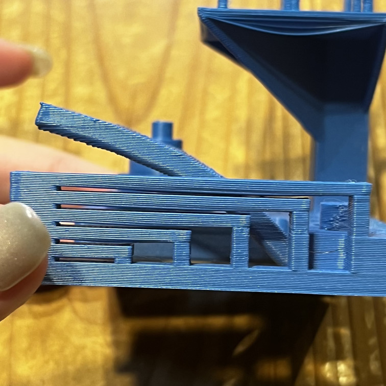
XY Resonance *Visually inspect the X and Y ringing features, illuminating the test print from the side to highlight any ringing captured in the print. This example would score 0.
If rippling in the X or Y axis can be observed at or past three hash marks, record a “0”, otherwise, record a “2.5”.*
rating: 2.5
Z-axis alignment If a layer registration effect with a period equal to that of the leadscrew is visible on the pillar supporting the fine positive features test, record “0,” otherwise, record “2.5.”
rating: 2.5
TOAL SCORE: 25
My conclusion: This printer is an overall workhorse. It manages overhangs really well and you can push it quite far before it requires supports, but it does tend towards stringing. This phenomenon fascinated me. So I decided to really delve into this for my individual assignment.
INDIVIDUAL ASSIGNMENT: 3D PRINTING: MALFUNCTIONS AS DESIGN TOOLS
As mentioned above, while characterizing the printer I was most fascinated by what the glitches that happened when I pushed the printer to the edges of what it was comfortable with.
The assignment was to design and create an object that could not be done with any other machine- So i decided to design using the printer settings to incorporate the printer malfunctions and unpredictabilities of into my design model. In my mind the struggle of the printer is a way to give it agency in the printing process and remove control from me- forcing me to engage more thoroughly with the printer settings.
INSPIRATION
I ran out of time, but originally what I wanted to do is to engage directly with the g-code and program extrusions, speed and heat irregularities directly into the code- following a randomness pattern BUT: I experimented for saturday and sunday and got nowhere, only malfunctioning g-code, as I had realised that g-code is machine specific and used for both additive and subtractive machines.
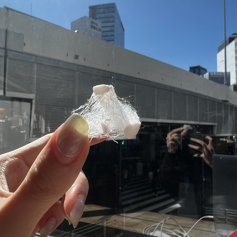
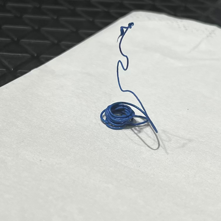
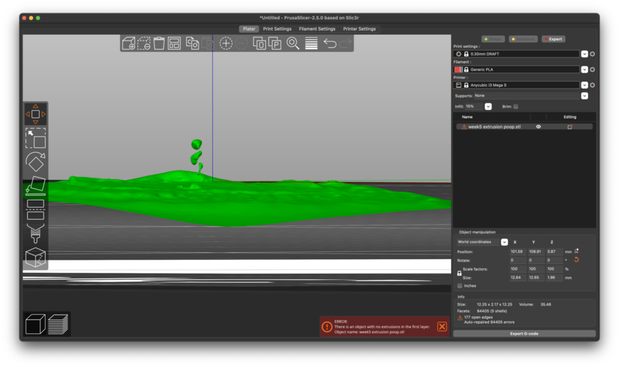
I was inspired to do this, based on the very first extrusion that the printer and gravity created when I was inserting the fillament. It was an object in it's own right and so I wanted to play around with the agency of the printer and the notions of what design really means when we are saying to create an object that could not be created any other way than 3D print. What is more unique to the 3D printer than his own extrusion and malfuntions.
Objects could be recreated by tedious hand-held methods as they have been for thousands of years, but 3D malfuntions are functions unique to the printer and controlling them is a design action in itself.
<3 My little extrusion poop:
First things first:
This weeks assignment was also about designing something that could not be created subtractively and understanding why: So in general the times to use 3D printing over CNC and moulding & casting is in the cases of overhangs und underhangs and when you have complex internal structures.
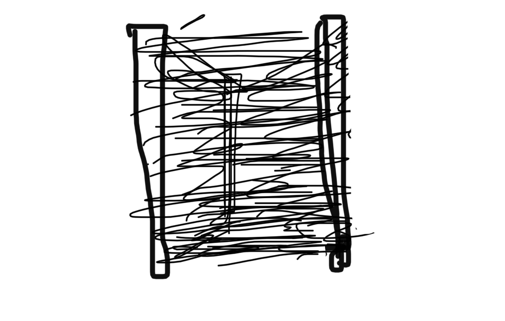
In my case I focused on the stringing: I wanted to achieve a fine spider-web like mesh between pillars. This effect usually occurs as a mistake- but I manipulated the settings to exaggerate the result and get a consistent fine string stretching between the pillars.
I made a quick of sketch of what I was trying to achieve:
Sketch
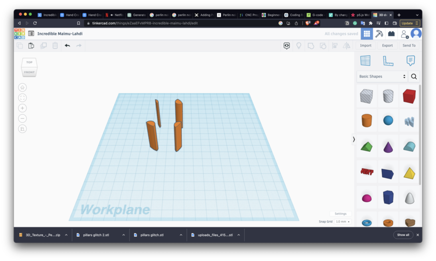
TinkerCAD
Because I wanted to do the primary aspect of designing using the settings of the printer, I just quickly designed irregular pillars in TinkerCad and exported them as .svg
PRUSA SLICER: CONTROL AND GIVING IT UP
Ironically in order to take control away from myself and give it over to serendipity I had to first understand the role of the all the settings and actually exert quite detailed control over the machine to give it the freedom to act beyond my wishes.
Since stringing is usually considered a malfunction, I jumped deep into tutorials and troubleshooting q&a's of people breaking down how stringing occurs and how to prevent it.
In short: stringing occurs when a small filament rest keeps on extruding while the extruder moves between multiple fine detailed objects. In order to get a cleaner print you could:
- increase the speed ( this would give the filament less time to leak- those the stringing would be finer and easier to remove.)
- decrease temperature: you can push this as far as you can to get a cleanest result- the thing to keep in mind that eventually when you go too low the filament will be not flexible and less binding to each other which would again make an unclean print in a different way
- RETRACTION: so most contemporary printers have a retraction mechanism build into the extrusion nossle. This feature pulls back the filament to keep it from leaking while the needle is traveling between negative space.
These were the three parameters I focused on!
To create stringing I fully turned off retraction and increased the temperature beyond what was advised for the filaments ( no by much, just enough to push the boundary) to create the optimal environment for leaking.
Then to add the spiderwebby nature to the stringing where it changes direction and varies in thickness I also adjusted the extrusion speed of individual layers. In the future I hope to add these parameters as a generative- randomness directly to the g-code, however for today I adjusted them manually.
I had to go into the advanced menu "expert settings". I did the following alterations!
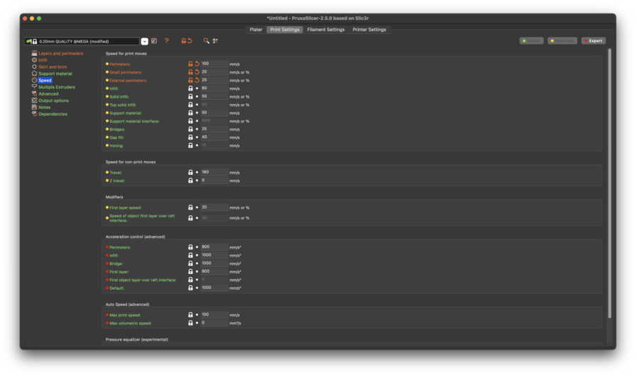
SPEED

I increased the speed for the premiters to ensure that they are clean. In other laters I adjusted the printspeed to be lower ( down to 20-60) especially on the inside lines
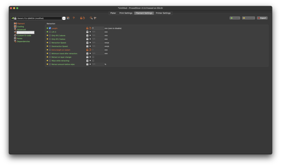
RETRACTION

LENGTH: 0mm = setting it to 0 disables the retraction funtion of the 3D-printers nozzel
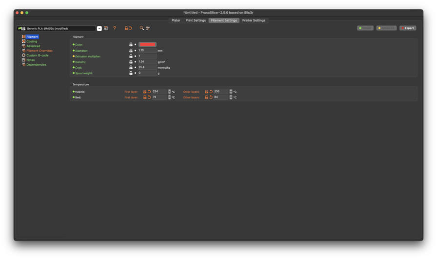
TEMPERATURE

I upped the nozzle temp for the first layer to 234 and to all other layers to 230 degrees ( right on the edge of what the fillament allows)

I also increased the temp of the bed to 84 degrees.
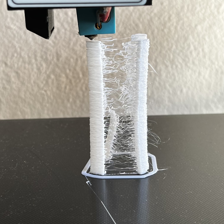
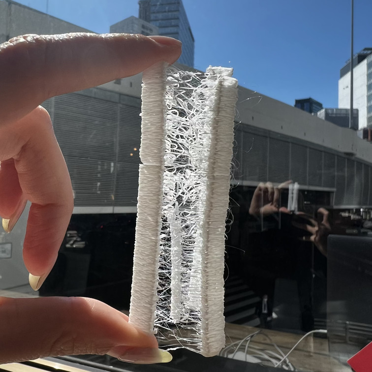
Final Result
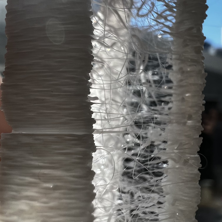
I succeeded in creating the spiderweb texture between the pillars and in having it strongly enough connected that the webbing forms an actual mesh between the pillars, rather than just fine hairs.
I managed to turn the glitch into a design feature using the printer parameters, and also such fine stringing would not have been possible using a subtractive method like cnc milling.
second spiral development
Further experimentation: I want to do these experiments:
-
Make a circular structure with webbing inside ( a more aesthetic design)
-
find a way to construct a model or g-code with generative perlin noise glitching.
-
I want to re-do the same experimental string shape using other fillaments, especially softer and more springy ones - I think that would improve the string durability and make it a more sustainable design element.
other experiments
I also tried to build a ball structure in TinkerCad, but ironically when I went to print it prusa-slicer told me the structure was too unstable to print

3D Scanning : A TALE OF MACHINE VISION MALFUNCTIONS
Part of this weeks assignment was also 3D scanning. For this I experimented with multiple various different scanners and apps on my phone.
But the overall 3D scanning experience became more of a philosophical exploration into machine vision and the paradoxical realities that come from that.
SENSE
The 3D printer in Kamakura is the SENSE scanner from 3D systems. However this scanner is actually 10 years and has now been discontinued.
Installing it on my mac brought up some fun pop-ups ;)
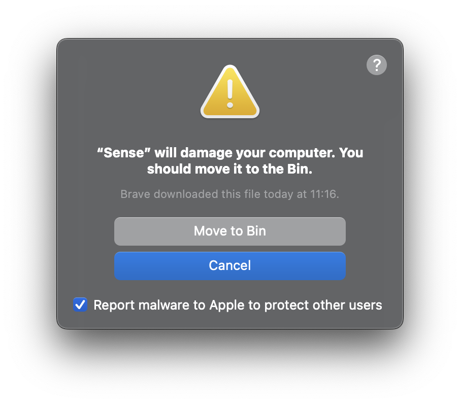
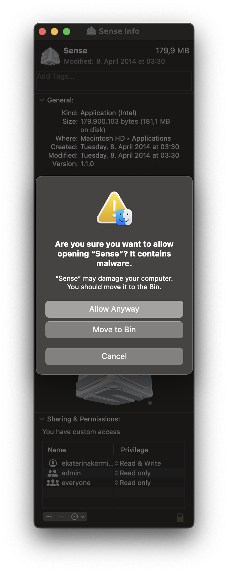
So I had to use the windows-laptop at the Kamakura lab and still attempted to 3D scan the original little object that the printer made my themselves.
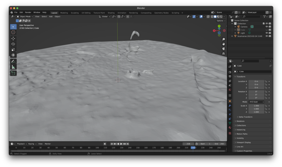
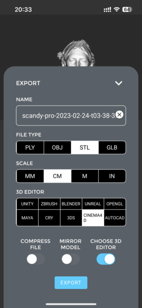
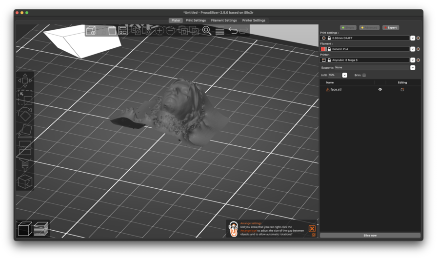
It didn't quite work. Because the object was too fine. Then I exported the models as obj's, which I can then open in meshlab or directly in Prusa Slicer.
I then attempted to clean the model in MeshLab, following Georg Tremmel's notes from 2021.
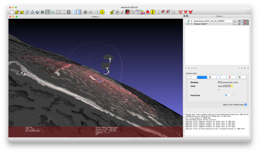
Filter > Normals, Curvatures and Orientation > Compute Normals for Point Set Filter > Remeshing, Simplification and Reconstruction, Surface Reconstruction: Screened Possion
and then I exported it as an stl and into prusa: it wasn't funktional lol.. i think i still have a lot to learn about how to make a 3D scan functional for 3D printing.
So instead I scanned a plant and other things using other phone lidar phone and photogrammetry apps.
Scanniverse
 !
!
I tried scanniverse on the iphone. It is a LiDar scanner that utilises the lidar on the Iphone13. It is obviously not as good as modern 3D scanners, but it does hold up. But sometimes I think I might get better results using photogrammetry, when it comes to objects, because the LiDar IOS scanners were actually designed for enviroments to create AR and 'virtual flat viewings' rather than having the fine-detection tools to be able to create models of individual objects.
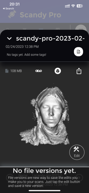
Scandy Pro
This was a weird one. When I opened it. It only let me operate the selfie camera, which was a truly odd way to try and scan anything other than myself.
I also guess that this app is only using photogrammetry since the front camera of the iphone has no Lidar functionality.
Its also a paid app and idk.. i don't like it so much. But I did manage to scan my face.