Weekly Summary
This week I 3D printed for the first time (yeah!). First we characterized in the group work our printers at FabLab Kamakura, then I designed and printed (after some failures learnings) a hinge that connects 2 cubes together - and allows a 180º rotation. This is a spiral development of my sketches from Week 2. We also used a 3D scanner to scan ourselves and a little buddha statute. My efforts to scan a really large statue did not come to fruition.
We also did photogrammetry on the Great Buddha of Kamakura, and then 3D-printed and compared all out buddhas.
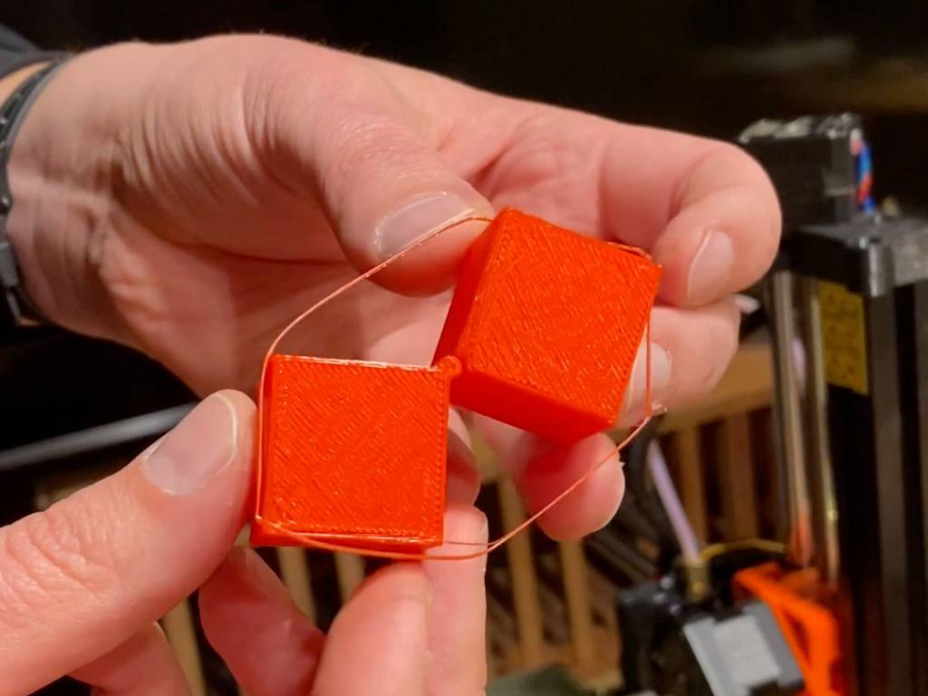
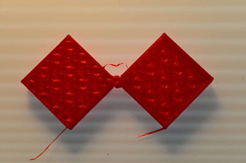
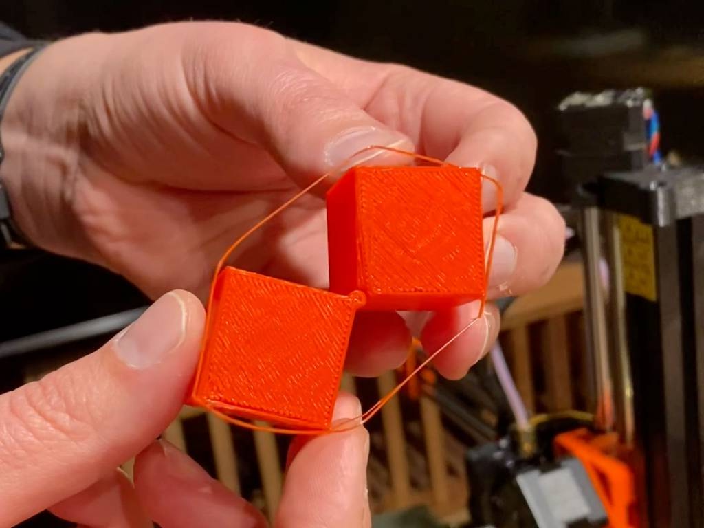
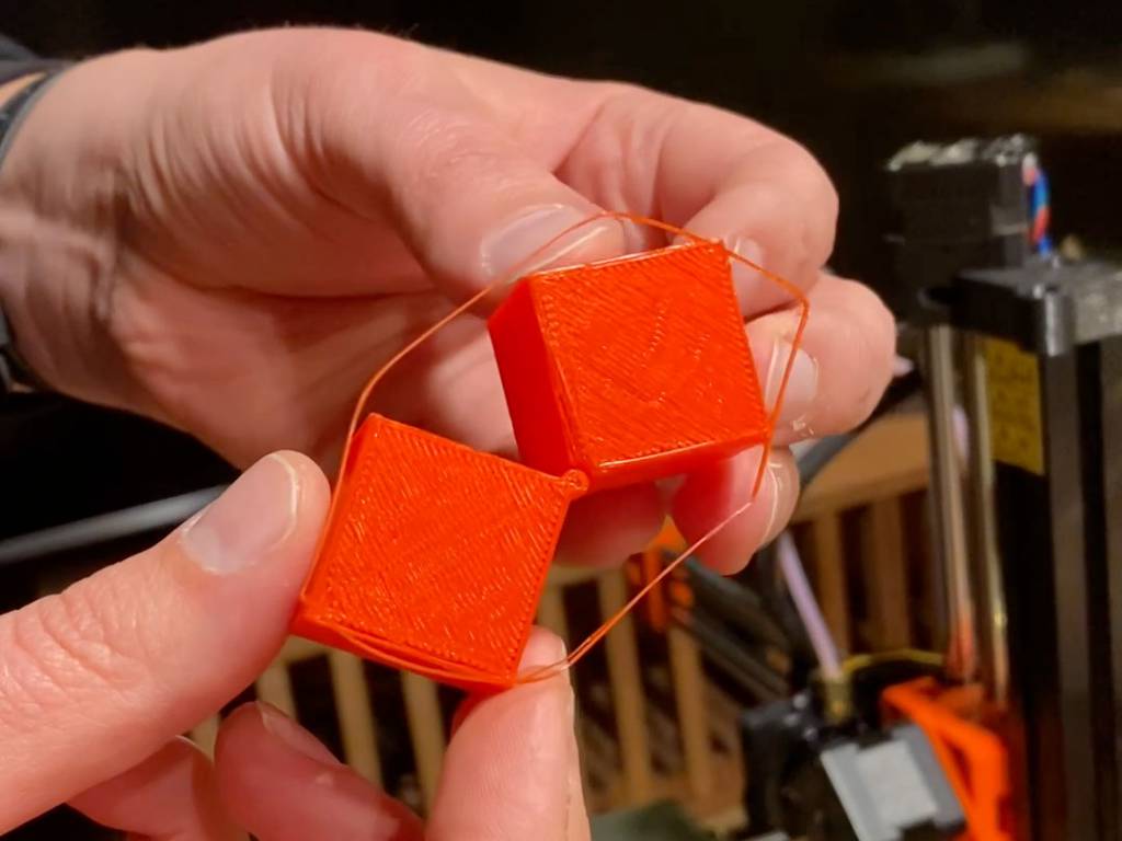
A 3D printed hinge with the pins in place, that can only be made additively.
Group Assignment
- test the design rules for your 3D printer(s),
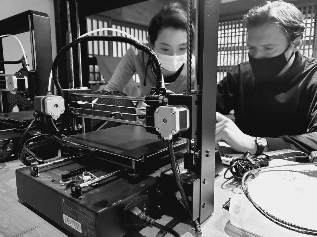
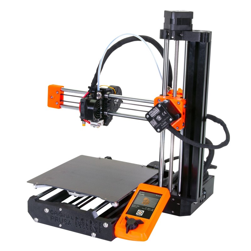
As we are 3 students at FabLab Kamakura, each could choose a printer and characterize it. Group Assignment Page↗︎ is the shared results of these efforts, here is also my assessment of the Prusa Mini (Thank you to Rico for borrowing the printer!):
For the characterization of the FabLab Kamakura's 3D printers, we choose each a printer and prepared and printer the All-in-One Object from Kickstarter-Autodesk-3d↗︎, local copy(612K).
This test geometry is testing the following, all with one object:
Dimensional accuracy (backlash optional)Negative feature resolutionPositive feature resolution/fine flow controlBasic overhang capabilitiesBasic bridging capabilitiesXY ringingZ-axis alignment
I downloaded the test geometry: https://github.com/kickstarter/kickstarter-autodesk-3d/blob/master/FDM-protocol/ksr_fdmtest_v4.stl
Using PrusaSlicer(on OSX 11.2.1), I imported the test geometry and choose the following settings:
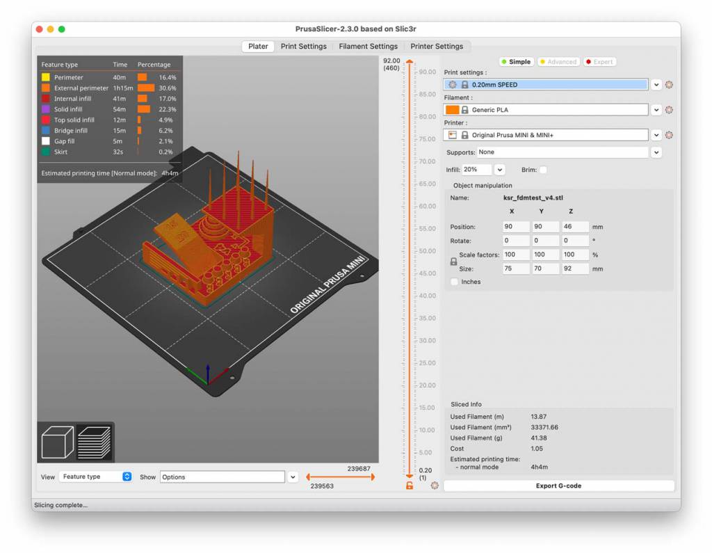
0.20mm SPEEDGeneric PLCASupports: NoneInfill 20%, no Brim
After slicing, that gives us the following:
- Used filament: 13.87m
- Cost: 1.05 ($?)
- Estimated Printing Time: 4h4m
Here is the exported Gcode file: georg_prusa_test_ksr_fdmtest_v4_0.2mm_PLA_MINI_4h4m.gcode , (external link, 7.3M)
Turning on the Printer
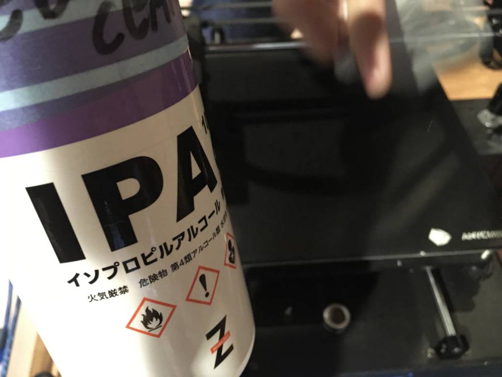
Cleaning the Print Bed
With Isopropyl alcohol, because it evaporates fast and leaves the print bed nice and non-sticky. And it removes residual oil from the printing bed.
Auto-bed Levelling
One USP of the Prusa Mini is it auto-bed leveling. Before printing a sensor reading of the bed is taken, and the bed is adjusted accordingly, resulting in better print quality.
Importing the Data
Is done via USB Stick, the interface is in color, no touchscreen and a rotate-and-push dial (similar to Bento Lab)
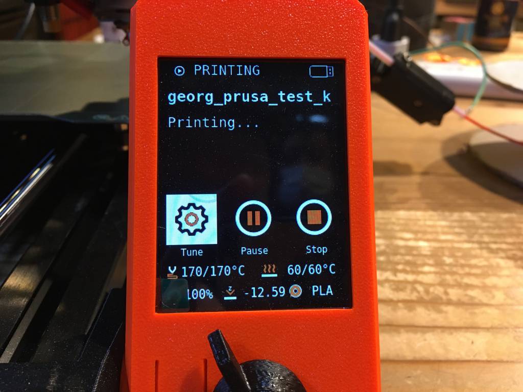
Starting the Printing
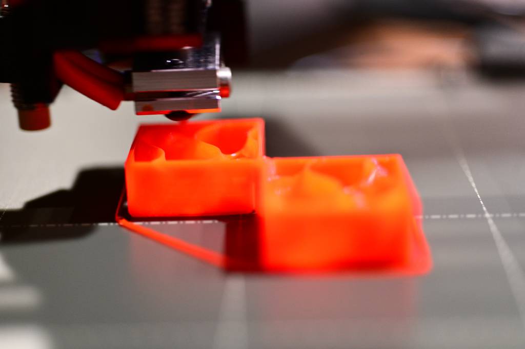
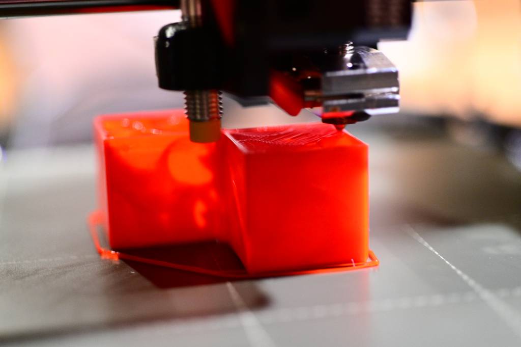
I started the print process, here are some images during printing.
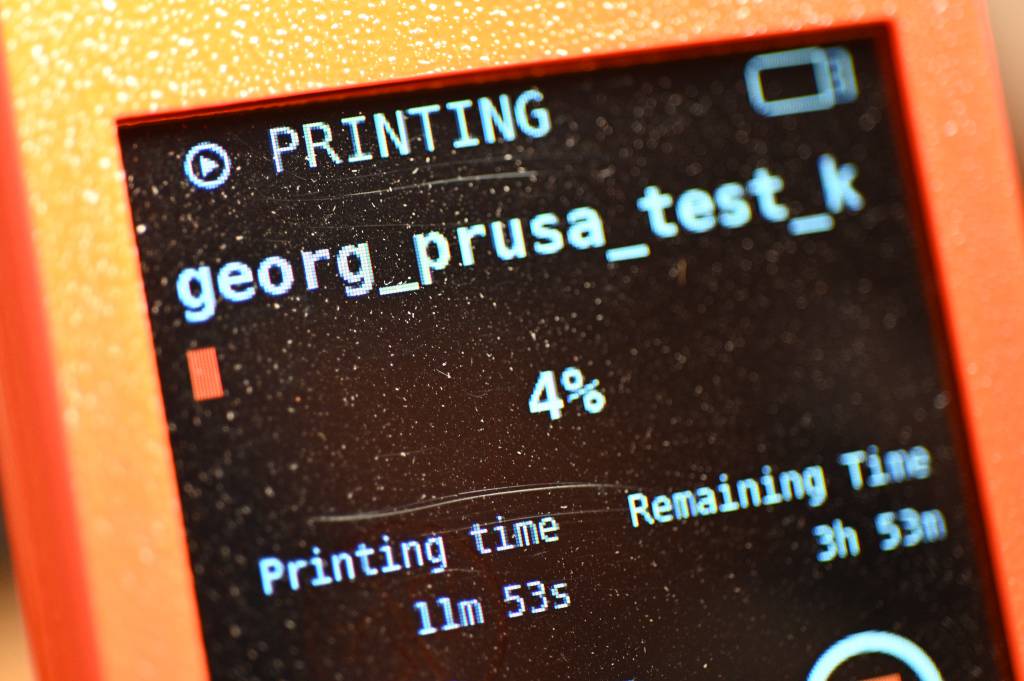
Printing Done!
Exactly 4 hours and 4 minutes later the printing was ready.
The main thing we choose this test geometry, was that it comes with it's own Assessment Protocol
Assessment
1. Dimensional Accuracy
I am measuring the x and y dimensions of the stack:
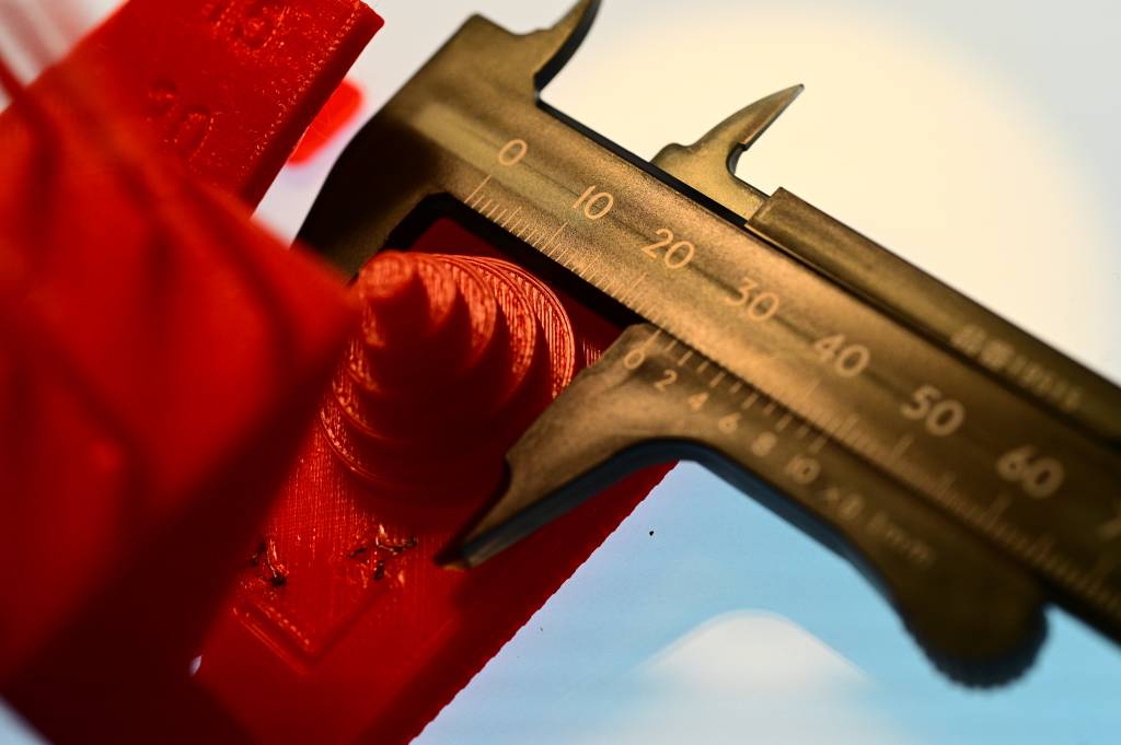
| Target | Measured X | X Error | Measured Y | Y Error |
|---|---|---|---|---|
| 25 | 24.8 | 0.2 | 24.8 | 0.2 |
| 20 | 19.7 | 0.3 | 19.8 | 0.2 |
| 15 | 14.9 | 0.1 | 14.9 | 0.1 |
| 10 | 10.0 | 0 | 10.0 | 0 |
| 5 | 5.0 | 0 | 4.9 | 0.1 |
- Avg Error X: 0.12mmm
- Avg Error Y: 0.12mmm
- Avg (Avg Error X, Avg Error Y): 0.12mmm
- Diff (Avg Error X, Avg Error Y): 0mmm
According to the guidelines:
- 0.00 - 0.10mm: 5 points
- 0.11 - 0.20mm: 4
- 0.21 - 0.30mm: 3
- 0.31 - 0.40mm: 2
- greater than 0.40mm: 1
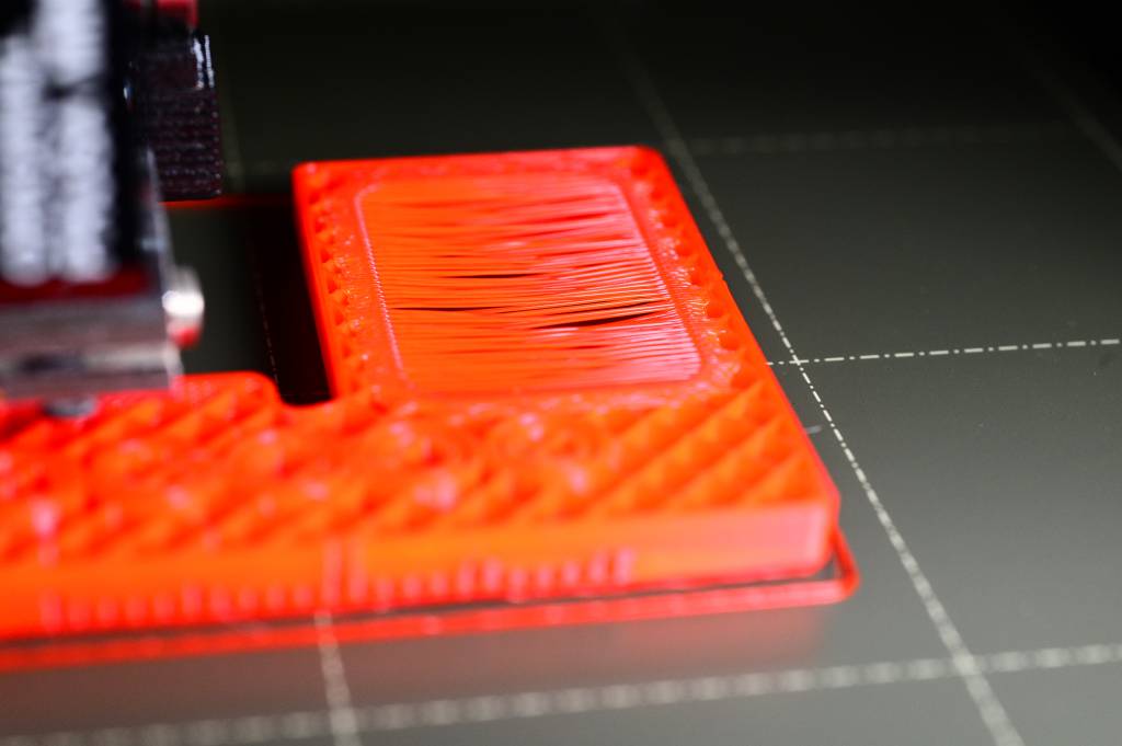
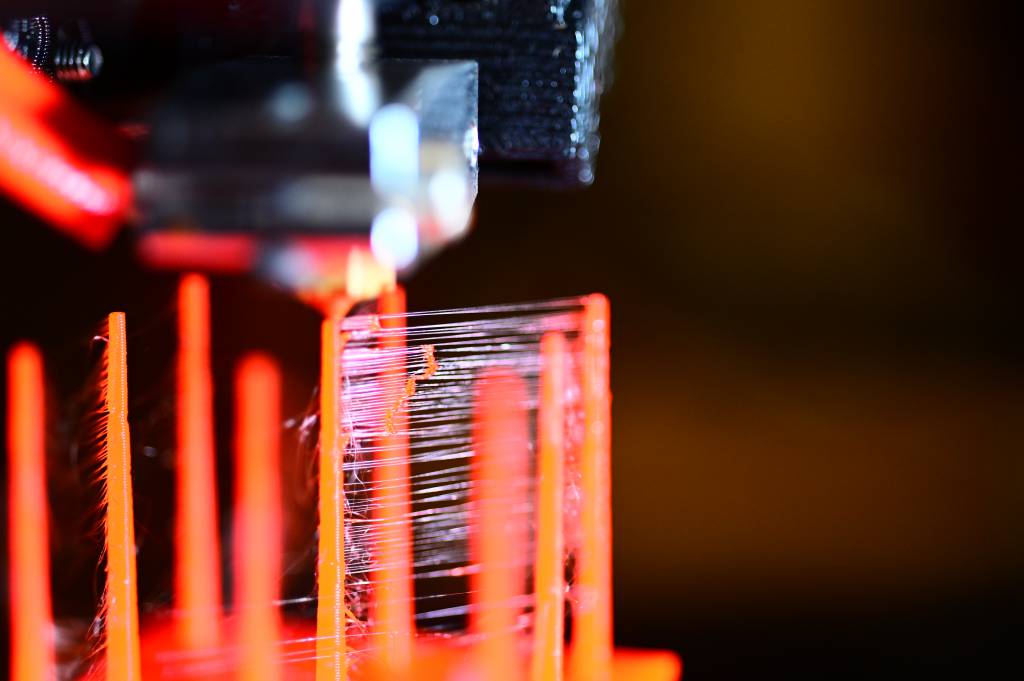
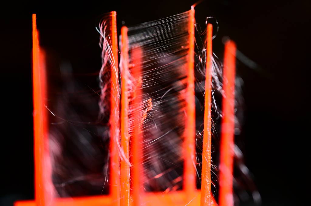
2. Fine Flow Control
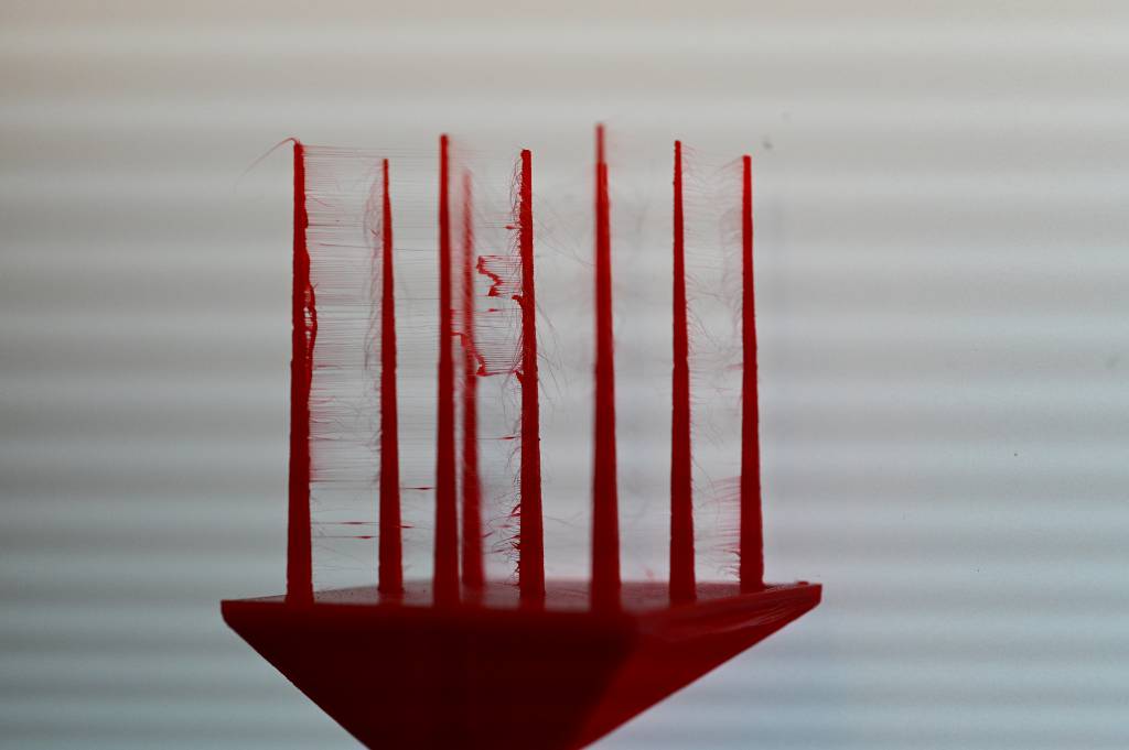
- Spines less than 30mm: 0
- Spines greated than 30mmm, but strings: 2.5
- Spines greated than 30mmm, no strings: 5
Spines 40mm long - fully printed!, but lot's of stings: 2.5
3. Fine Negative Features
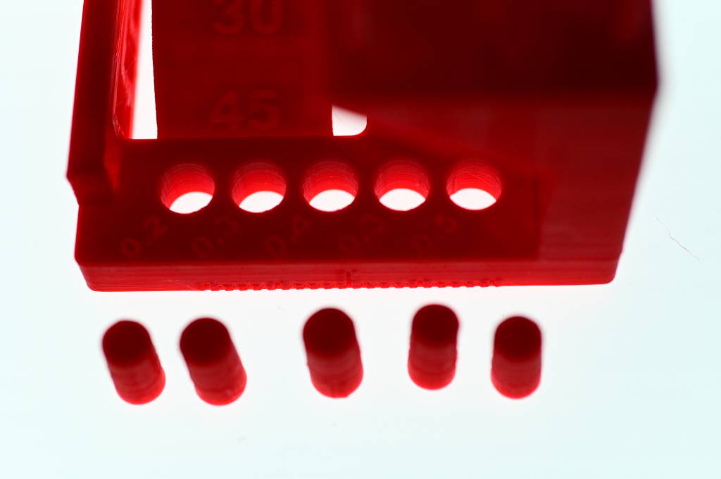
How many pins can be removed from holes, using only finger pressures, no tools? All can be removed: 5
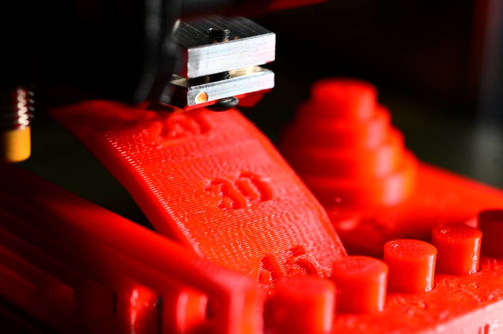
4. Overhangs
- Dropped loops everywhere: 1
- 15, 20, 30 differ from 45: 2
- 15, 20 differ from 45: 3
- 15 differ from 45: 4
5. Bridging
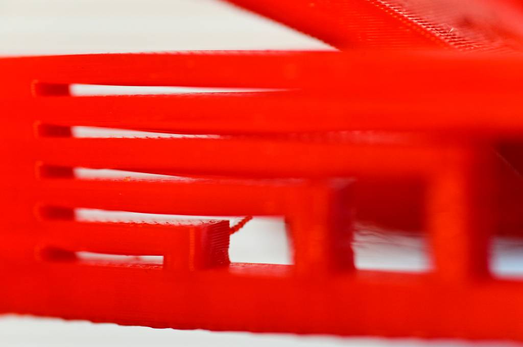
- More than 3 contacts within the bridges: 1
- 3 contacts: 2
- 2 contacts: 3
- 1 contact: 4
- No contact: 5
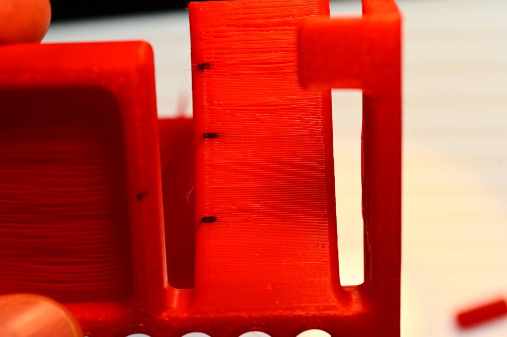
6. XY Resonance
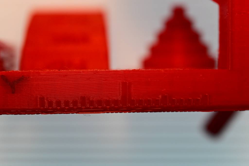
Visually inspecting the ringing feature, for both X and Y:
- If ringing more that three hash marks: 0
- No ringing: 2.5
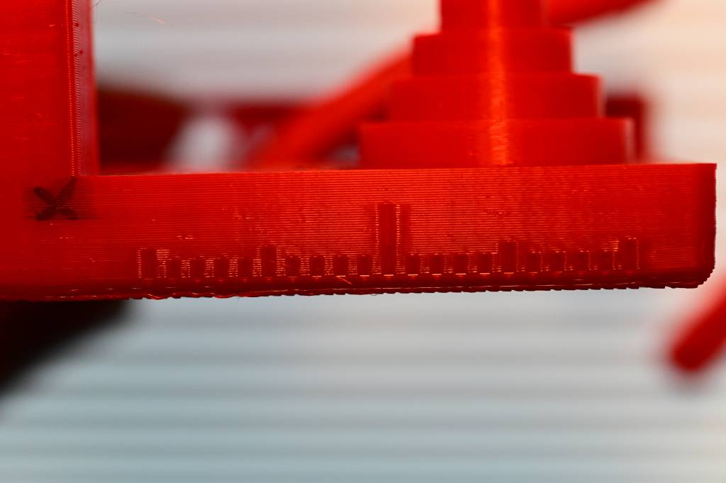
7. Z-axis alignment
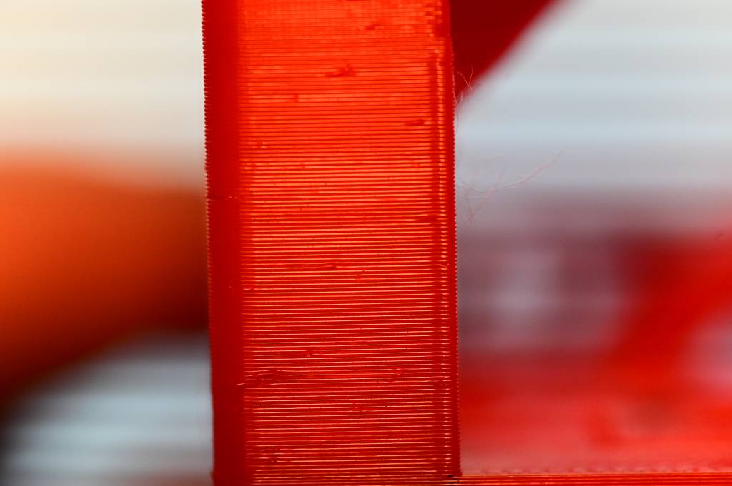
Is there a registrations effect with a period equal to the leadscrew? If so, 0, otherwise 2.5.
No, no registrations: Score 2.5
Summary of the Assessment
| Check | Points |
|---|---|
| Dimensional accuracy | 4 |
| Negative feature resolution | 2.5 |
| Positive feature resolution | 5 |
| Overhang | 3 |
| Bridging | 3 |
| XY ringing | 2.5 |
| Z-axis alignment | 2.5 |
| Total for Prusa Mini: | 22.5 |
- Highest Possible: 30
- Prusa i3 MK3: 22.5 (same as our Prusa Mini!)
- Makerbot Replicator 2: 18
(But we don't know Slicing Parameters and Printing Times for these)
Conclusion
First time doing 3D Printing, very impressed with the results - and ease of use of the Prusa Mini. Mini+ just came out, would be nice to get one.
Individual Assignments
While the test object was printing - and all the printers were occupied - I finished the modeling of my subtractive piece. I am still in the process getting fluid with Fusion 360, modeling is taking longer than I expect it to.
3D Printing
I am spiraling up from the work from Week 2, where I sketched and prototyped a modular, configurable test tube stand. The unresolved issue, is how to connect the cubes together - and allow their 180º movement.
This week, I am concentrating on the hinge mechanism.
Design Process in Fusion 360

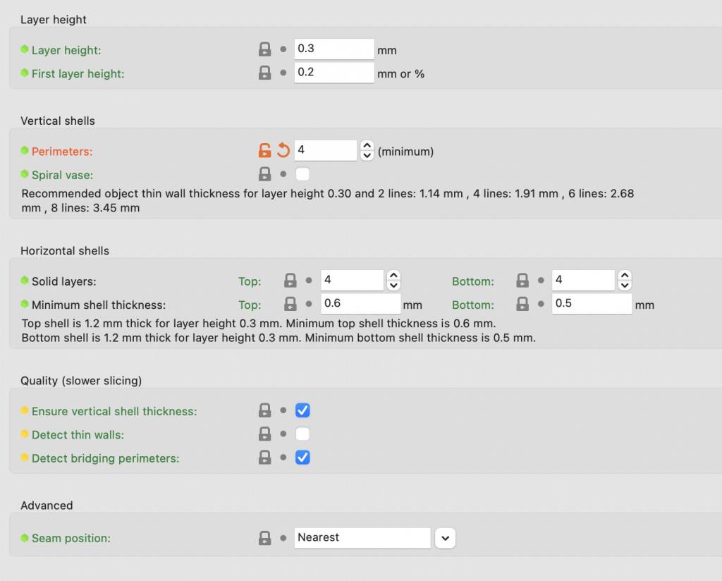
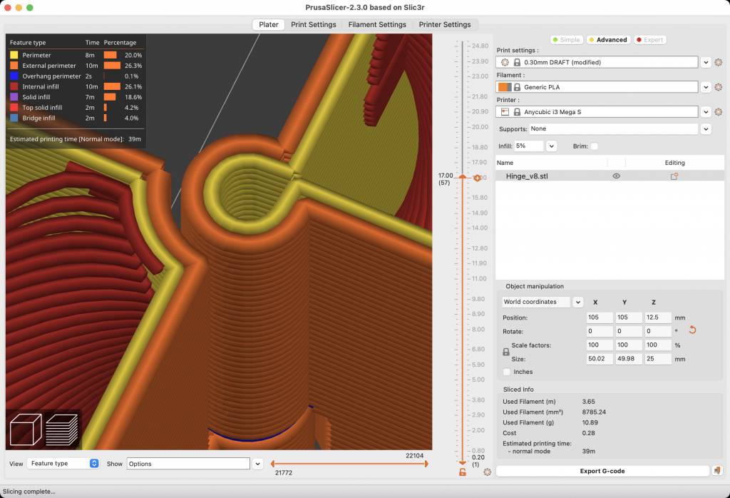
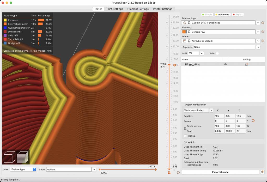
Slicing with PrusaSlicer
Slicing and Slice Settings are crucial, as they have a direct impact on the strength of the hinge.
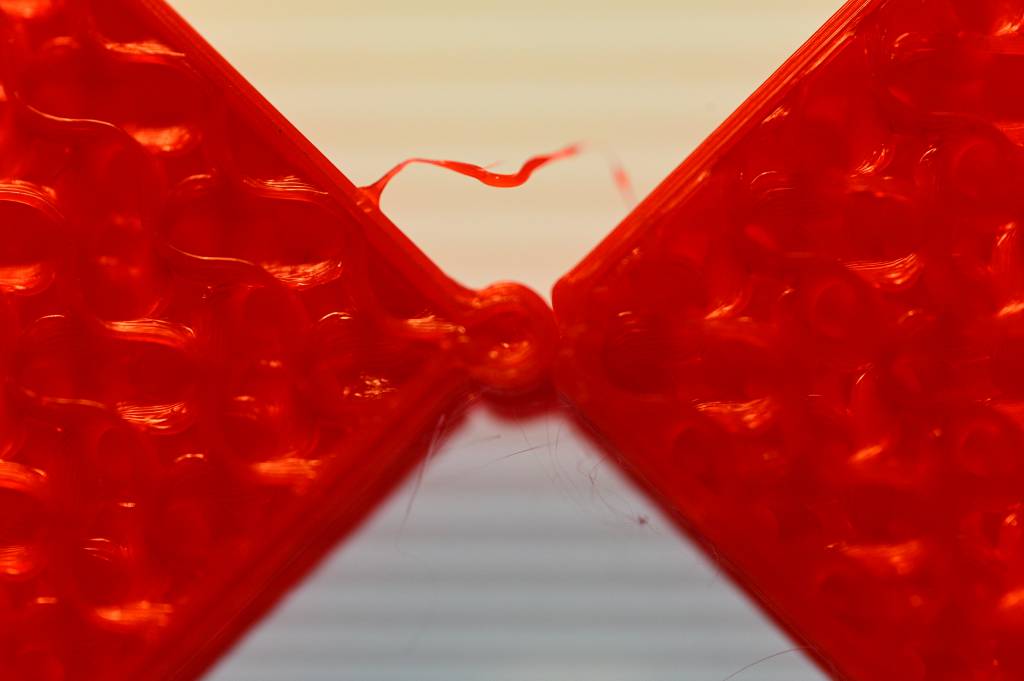
Approach 1: Living Hinge (Failure)
I was curious if a living hinge could be printed with PLA. I modeled a test living hinge...
... printed it, ...
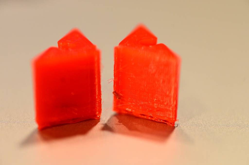
... and it immediately broke (faster than I could take a picture).
Apparently PLA is the wrong material for living hinges. My finial test tube stand will be a series of cubes connected with hinges. The hinges are the weak point, therefore I was also experimenting with being able to change the hinge only - and leave the cube intact. (I did not follow this avenue further, as the priority of the lab day was to get the assignment done. To be continued.)
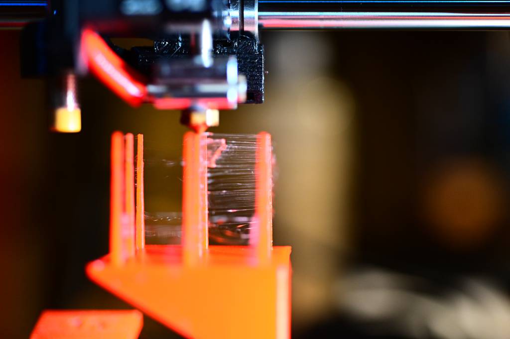
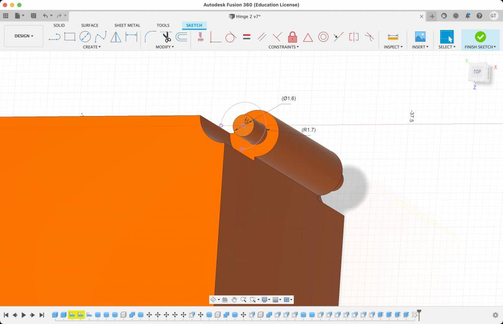
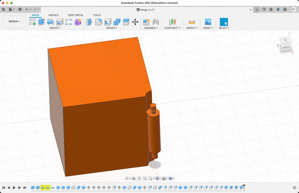
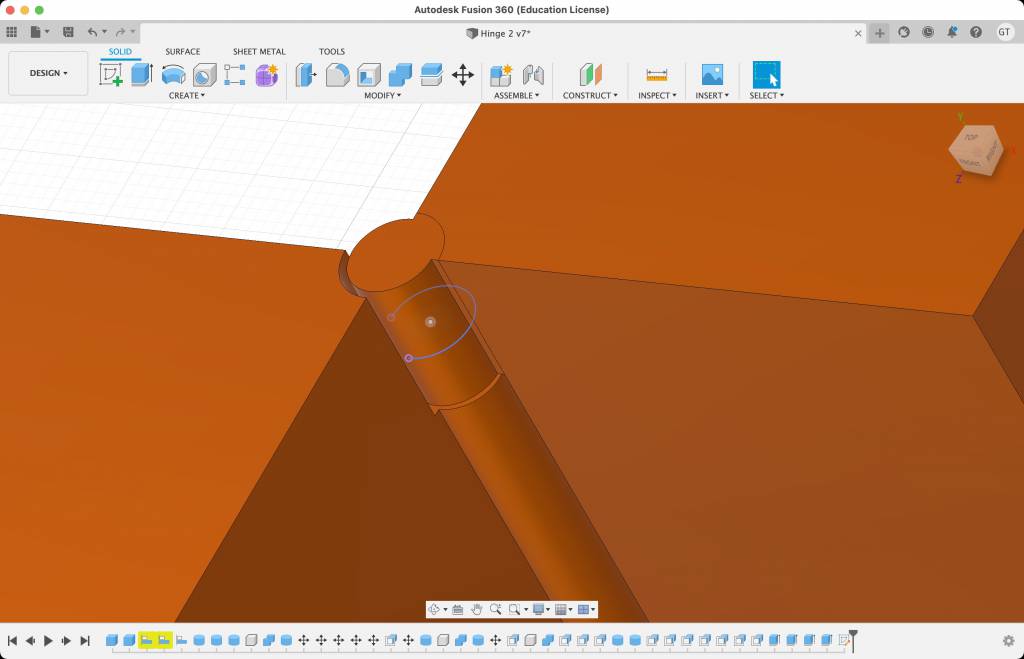
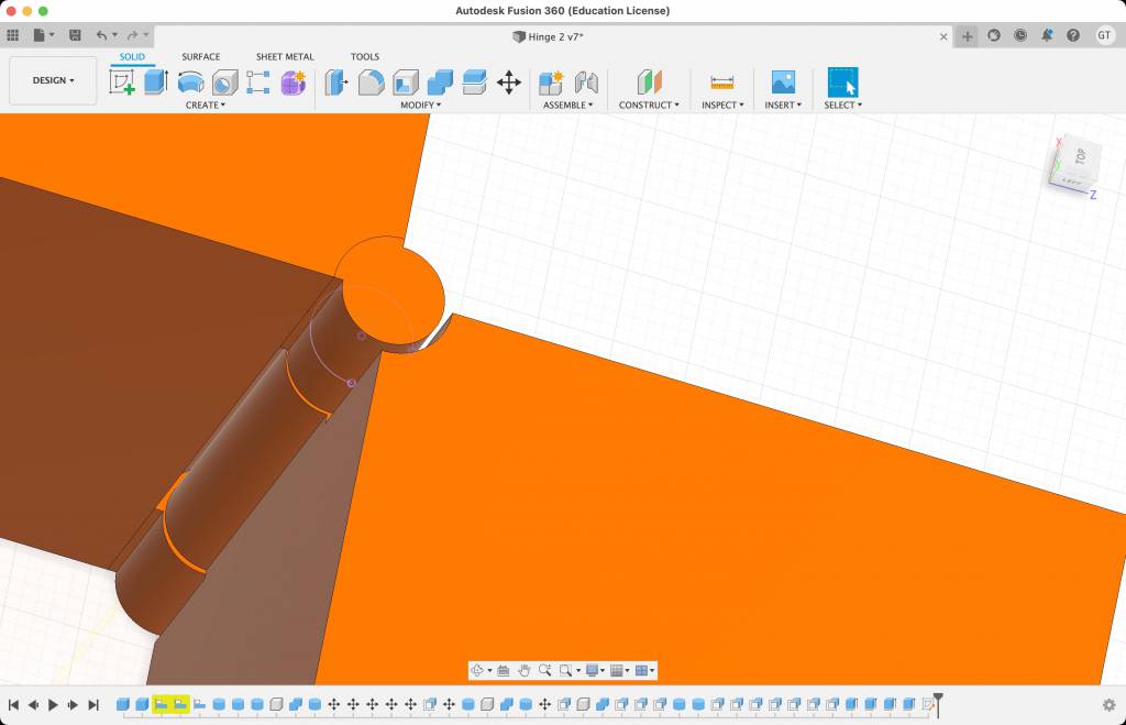
Approach 2: Pin Hinge, Printed in Place
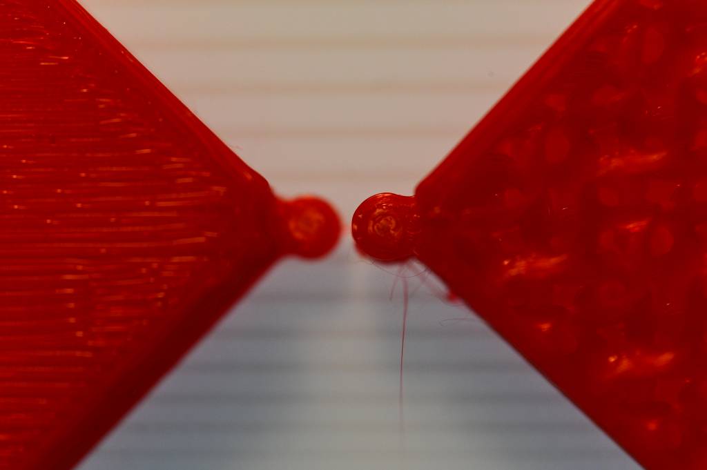
The second approach - which hopefully also qualifies a being made additively - is the Pin Hinge Approach. The challenge was to get the clearance of the hinge, cube and pin right, so it would not fuse - and also not allow to much travel.
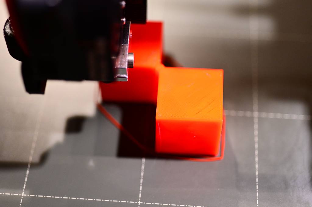
Print 1
I could see after 10 minutes of printing, that I set the clearance parameter too low (0.1mm), the two cubes are fused together.
I stopped the print and started redesigning.
Failure.
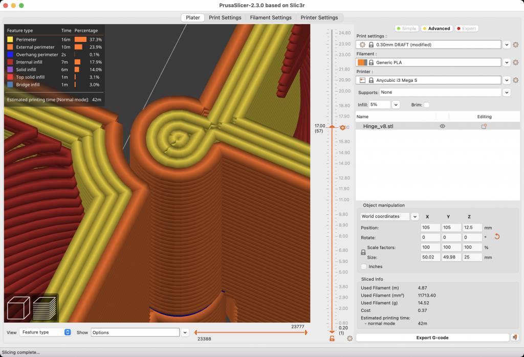
Print 2
I increased the clearance to 0.2mm and printed again. This time it passed initial visual inspection, the cubes did not fuse immediately. But when the printer came to the hinge, I could see again the the clearance was not enough, the cubes would move, but they would probably break the hinge. I stopped printing and confirmed my suspicion.
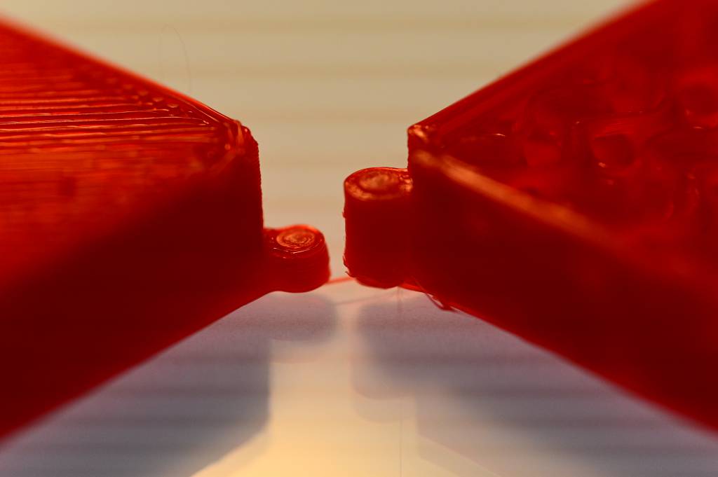
Failure. Stop. Redesign.
Print 3
Ok, this is looking good...
And here it is, hot off the printer!
Hero Image
Hero Video
Conclusion
I did my first 3D prints today, 3D printing is working better than I expected, - and the printing time is longer than I expected. The bottleneck - for me - is still the design process.
Next Steps
- Design the modular cubes
- Design replaceable hinges for the cube
- Print in different colors and/or materials
3D Scanning
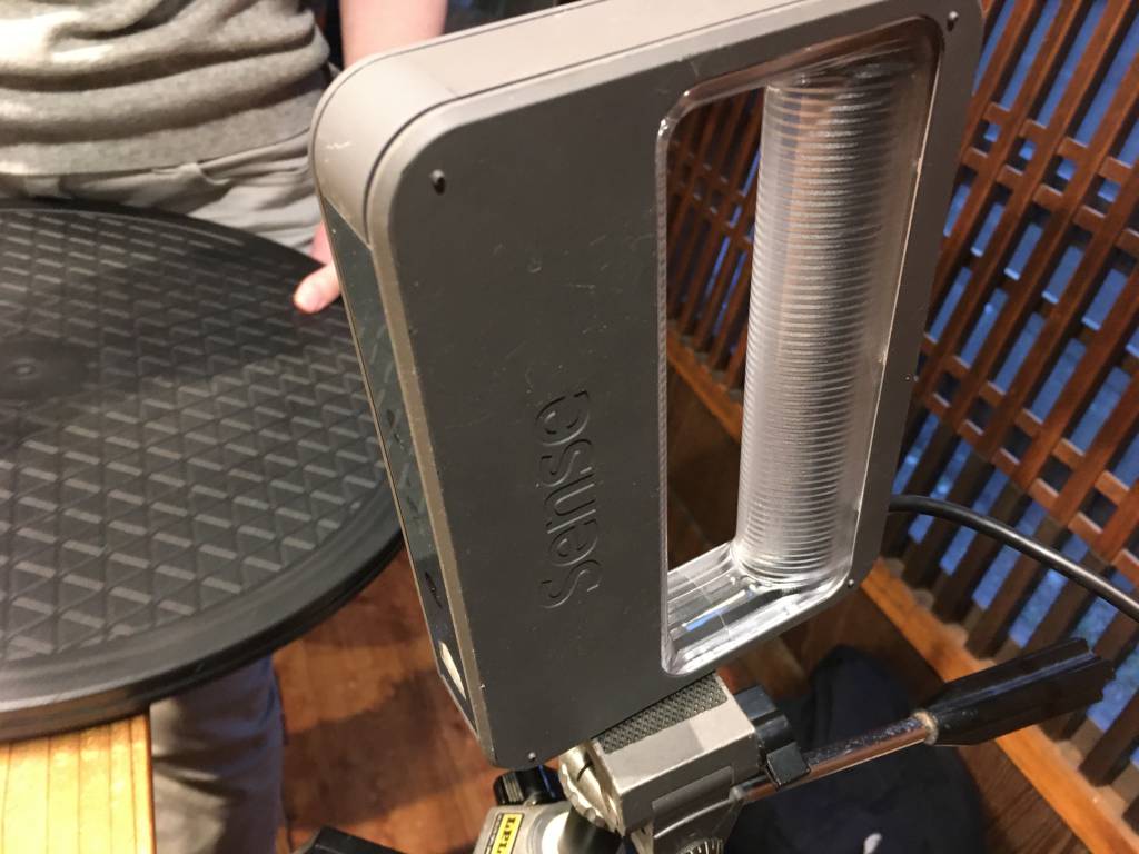
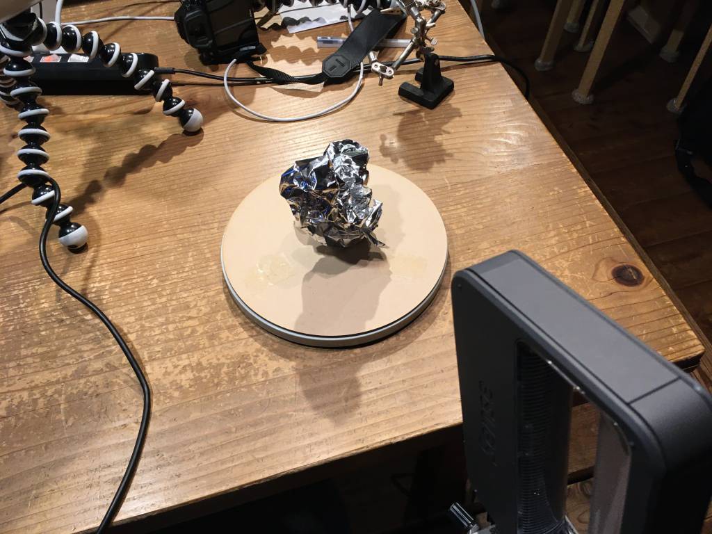
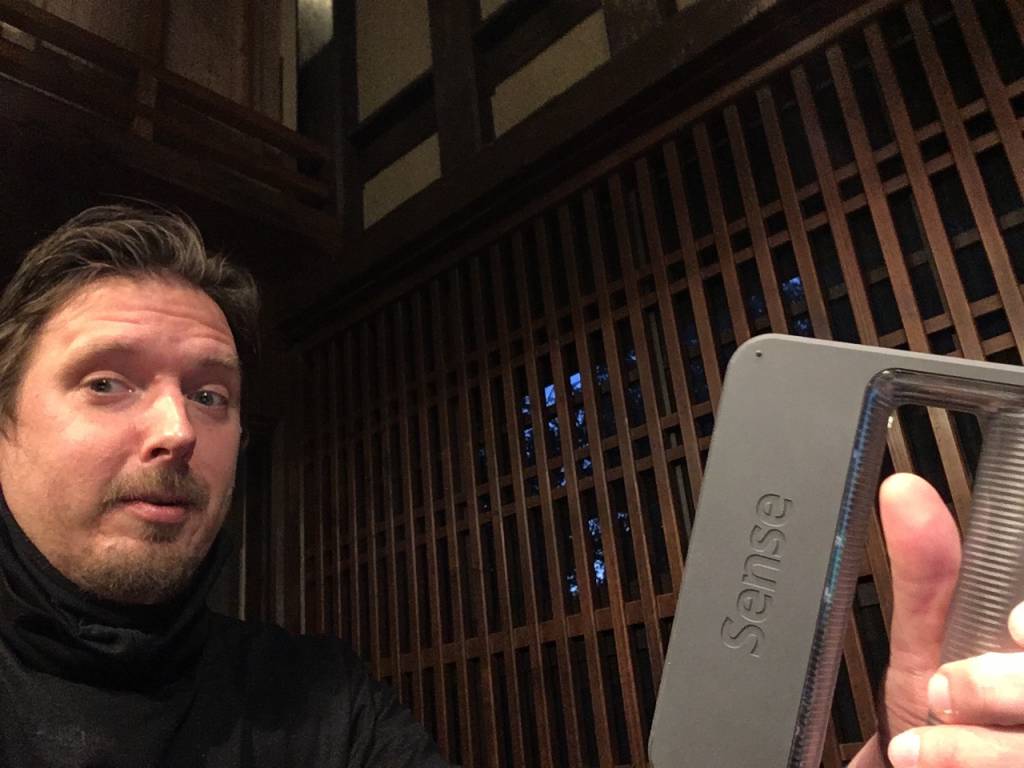
Testing the Scanner and 3D-Selfie
We used a Sense Version 1 3D Scanner from 3D Systems. We tried to scan a object on a turntable - we learned quickly, that the object can not be shiny. And that the black hair of my colleagues here in Kamakura is also too shiny!
We resorted quickly to scanning ourselves, also trying to do a 3D selfie scan:
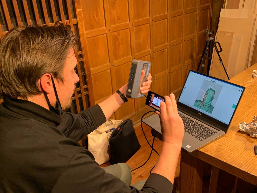
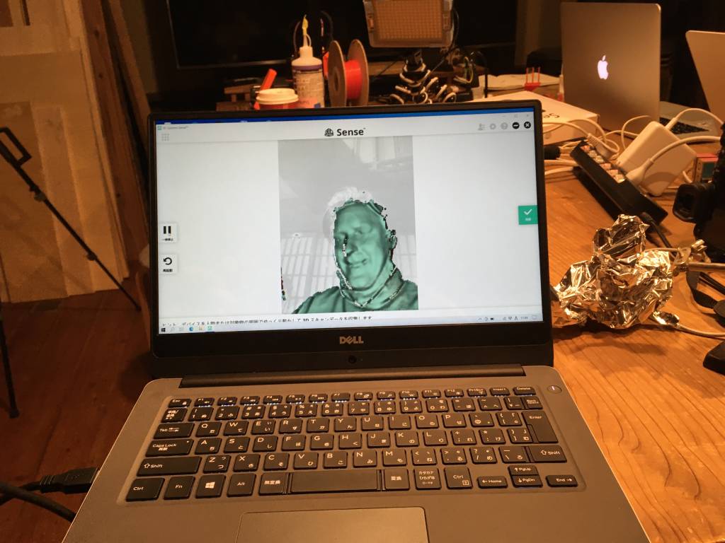
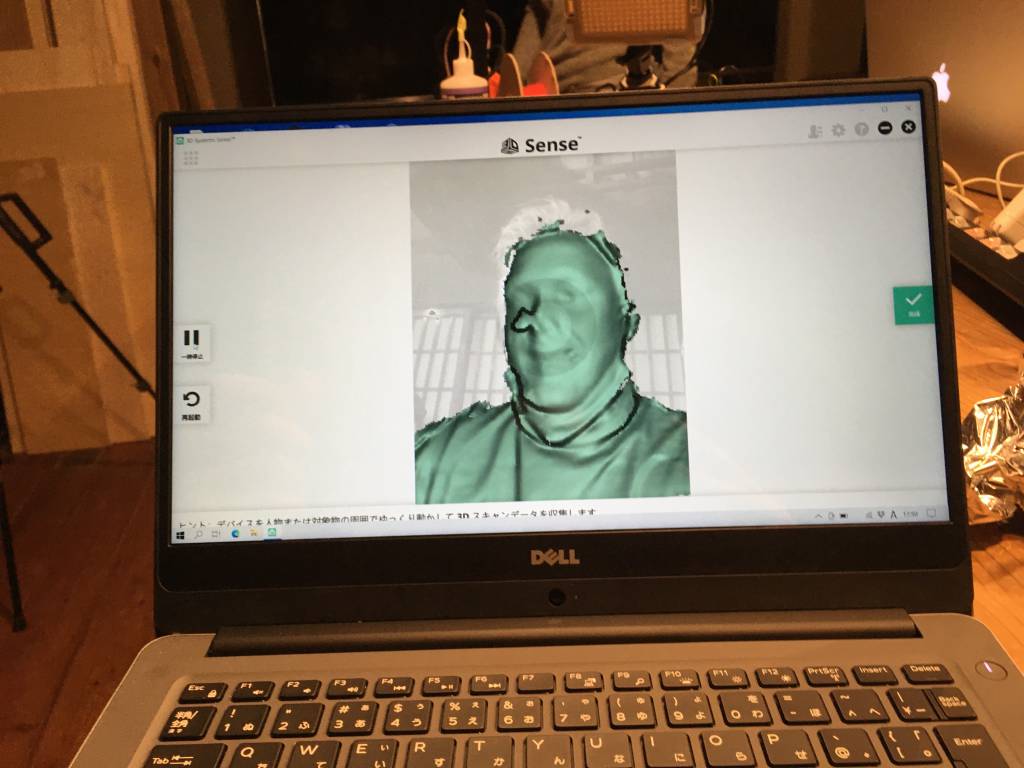

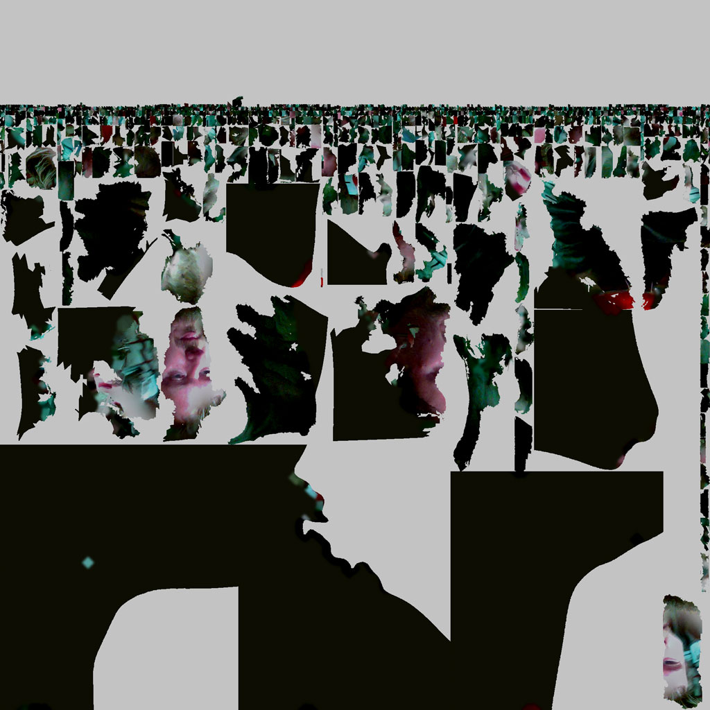
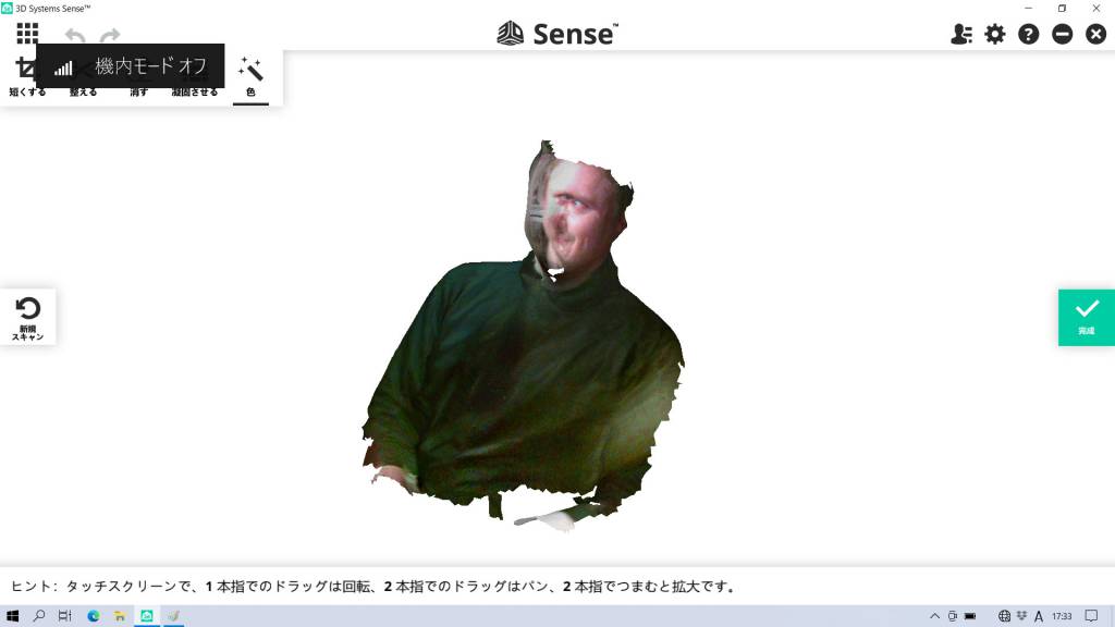
Here is the resulting scan. Great fun, still looking for a practical application.
3D Scanning and Printing a Small Buddha
I used the _Sense Version 1 3D Scanner? again to scan a _Small Buddha.
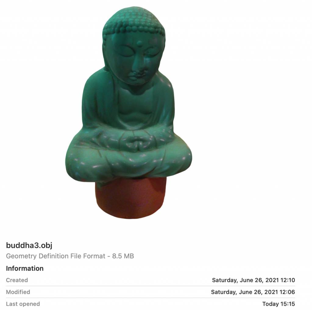
Printing the Scan
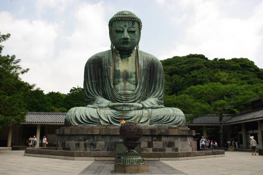
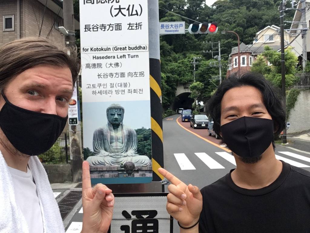
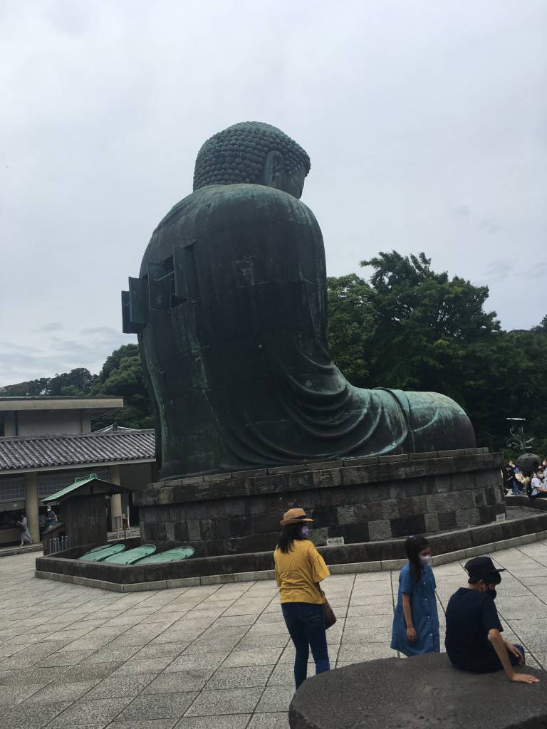
Photogrammetry-ing the Great Buddha of Kamakura
A bit of history
Kamakura is famous for being the de-facto capital of Japan from 1185 to 1333 - and for the Great Buddha of Kamakura ("Daibutsu"), a monumental outdoor statute of Amitābha the Buddha of Immeasurable Light and Life. The statue is more than 13m high, measures more than 100 tons, when I visited it the first time - some year ago - it was still possible to get inside that statue. This is currently not possible. The statue was completed in 1243 and was originally house in a hall, which was destroyed by a storm, rebuild, destroyed again. In 1498 a tsunami destroyed the hall once more, since then the Great Buddha has been been outside.
Attempt 1
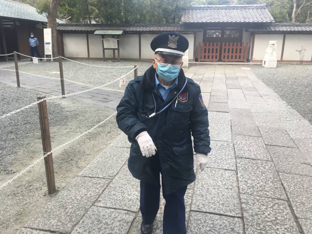
I wanted to take images and photogrammetrically reconstruct the large, and well-known Buddha stature of Kamakura. I arrived at 15:46 at the place. The ticket both closed at 15:45, and although visitor were still inside, it was not possible to get. (I tried with all my charme!)
Attempt 2
Together with Kai Naito we made another visiting attempt. This time we succeeded.

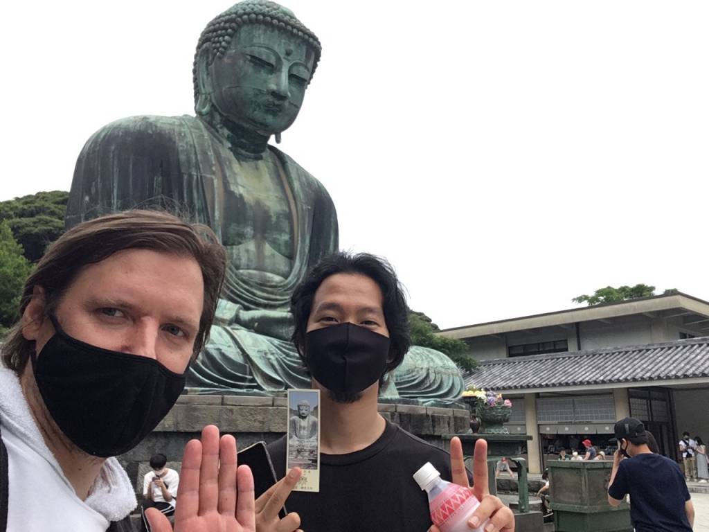
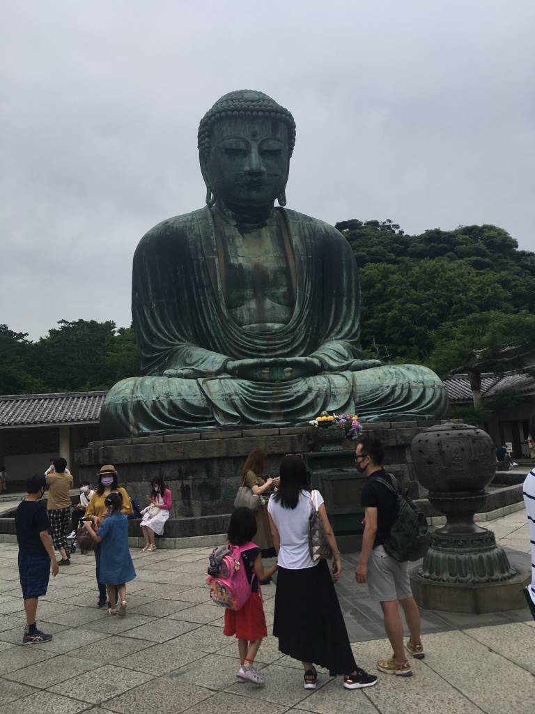
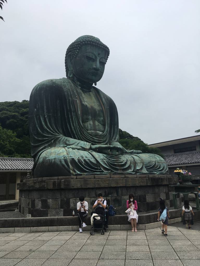
Together we made more than 250 pictures of the Daibutsu. Here are some examples:
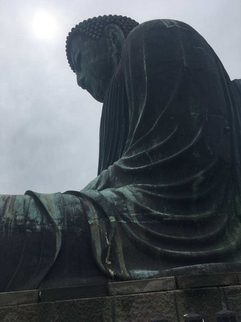
The total file-set is more than 500M, download it from here.
Photogrammetry
Photogrammetry is the reconstruction of 3D objects and scenes from a large number of overlapping photos.
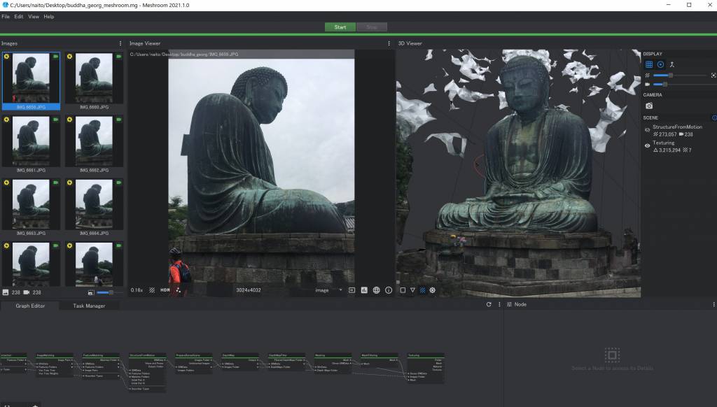
Meshroom is a free and open-source 3D Reconstruction Software, that runs on either Windows or Linux, but in any case it needs an NVIDIA GPU - which my MacBook does not have.
For Photogrammetry on the Mac there are some tutorials that workaround the GPU challenge. This tutorial, aptly named 'Photogrammetry for Mac Users' is suggesting to use the following freely available applications:
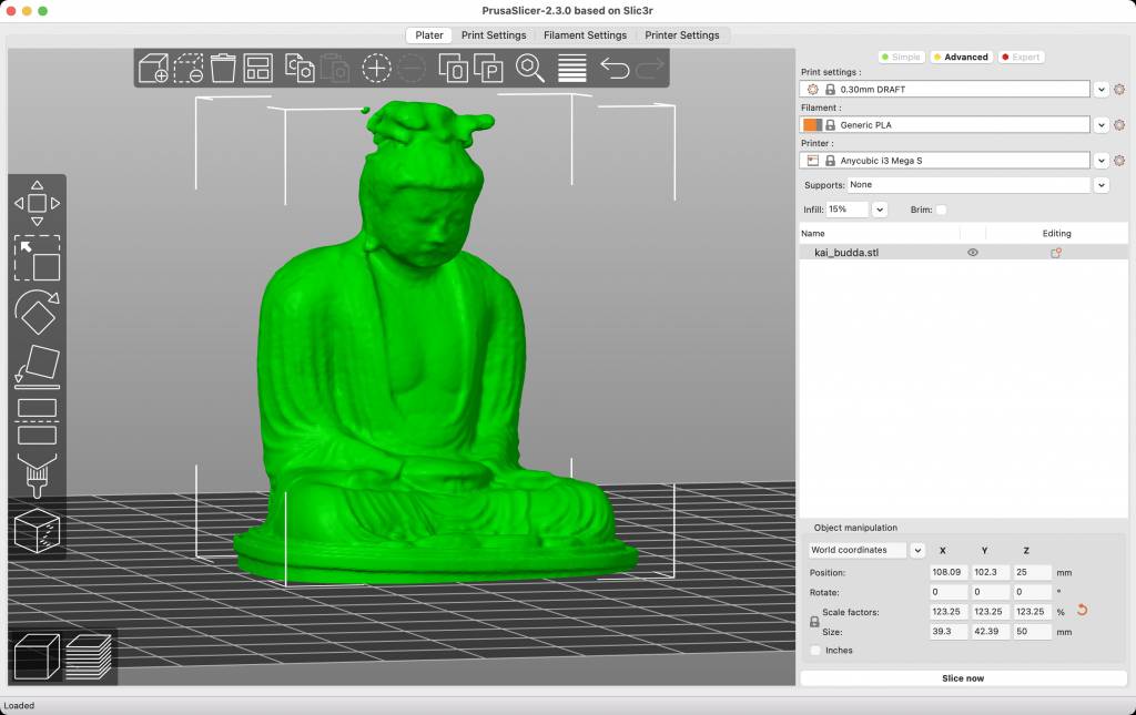
Photogrammetry with NVIDIA
Kai-san also ran the picture-set through Meshroom on his Windows Laptop.
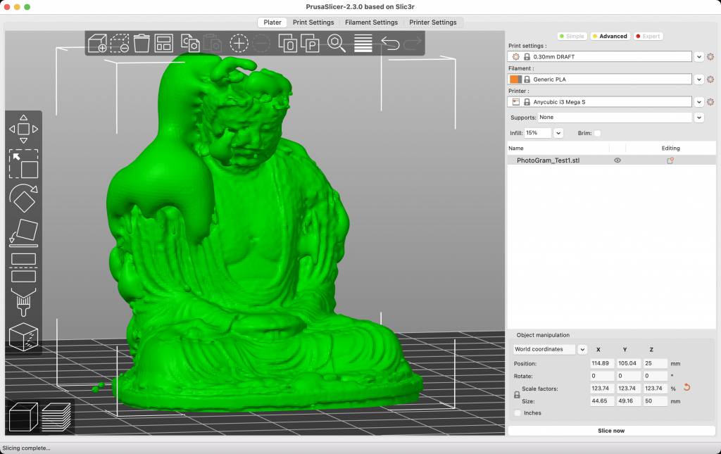
Photogrammetry on the Mac
I also wanted to run Photogrammetry on my Mac - in order to compare if the NVIDI/Meshroom or Regard3D/Mac workflow yields the better results.
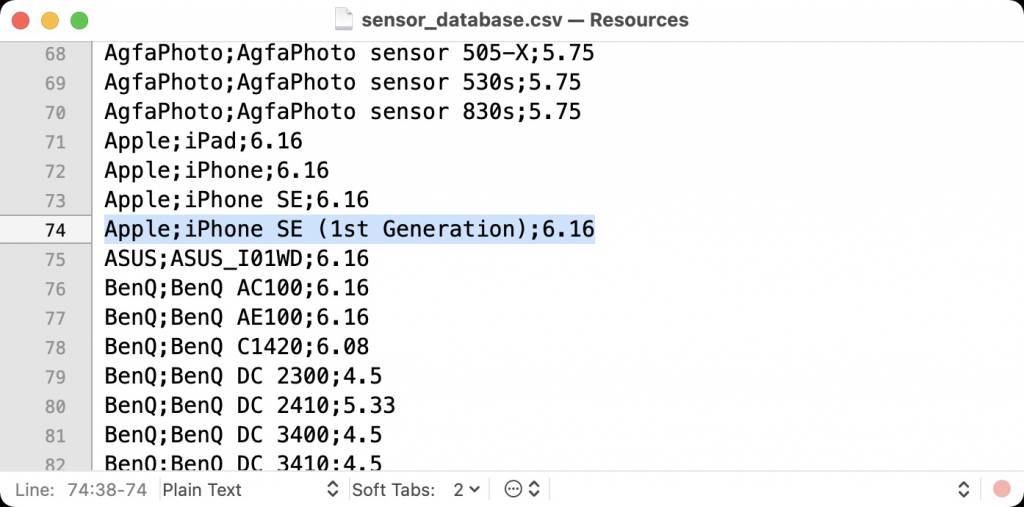
Adding Camera Info to Regard3D Database
Regard3D needs to know the sensor size and aperture of the camera with which the pictures were taken. Very likely your camera is NOT part of the build-in database. In that case open the /Applications/Regard3D.app/Contents/Resources/sensor_database.csv and add the camera info and sensor size.
Import the Pictures & Compute Matches
Following the tutorial, I created a Picture Set, imported the images and clicked Compute Matches.

figcaption>Computing Matches
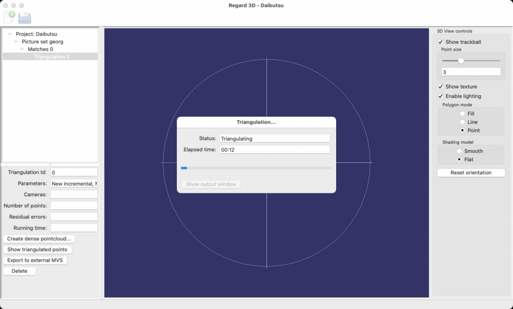
Triangulate
Once the matches are computed, the next step is to triangulate the matches.
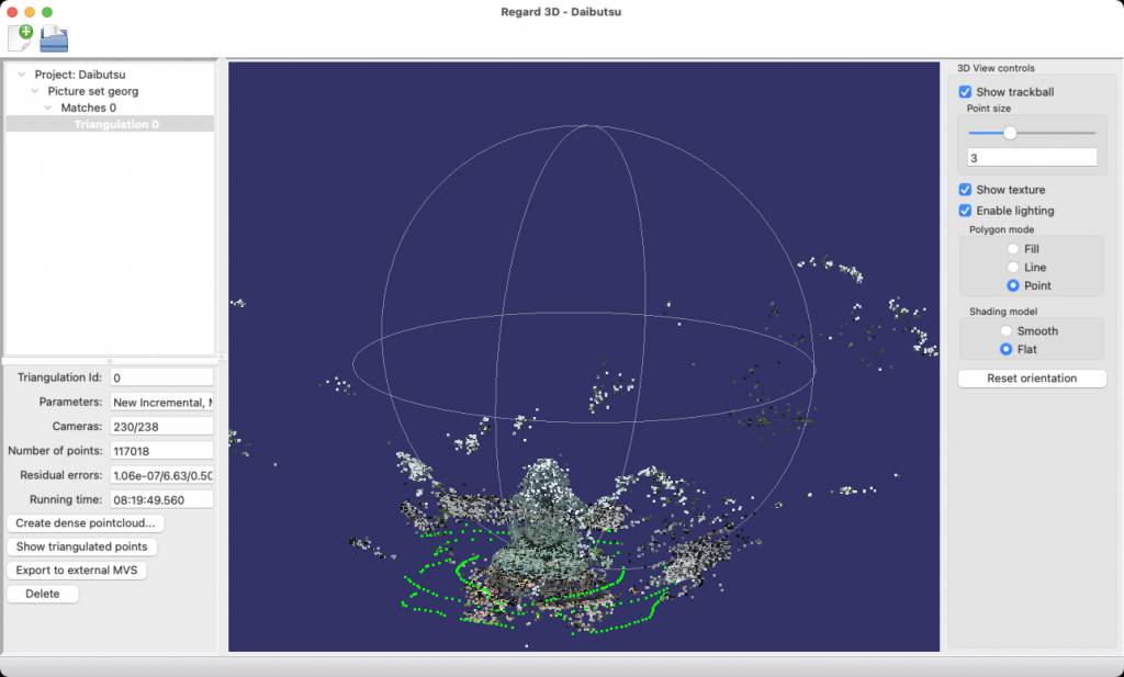
Create Dense Pointcloud
Then, click Creating dense pointcloud... which will result in something like this:
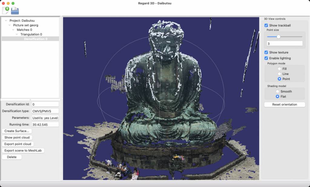
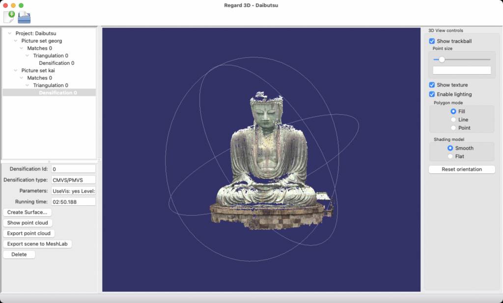
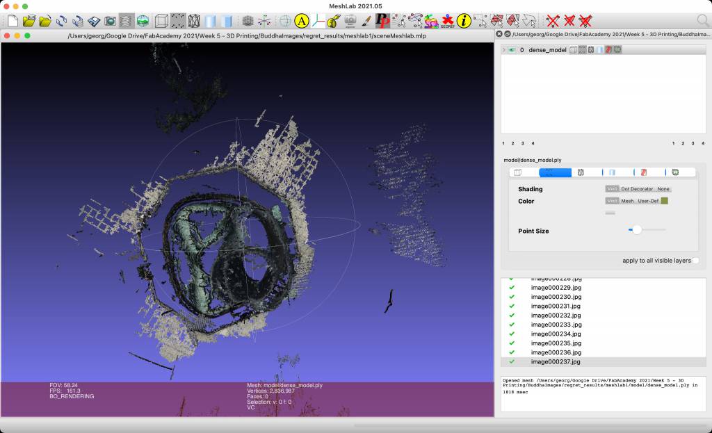
Once the Pointcloud is created, you can either export the point cloud, or export the whole scence for use in MeshLab.
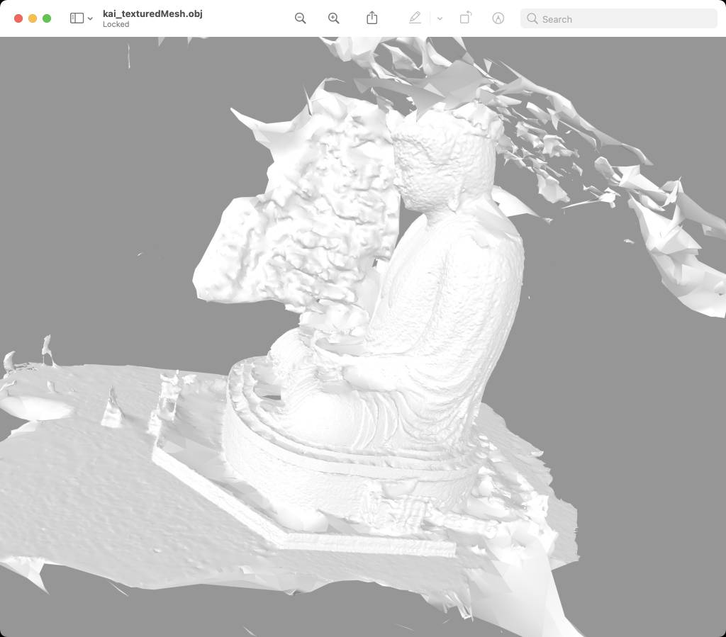
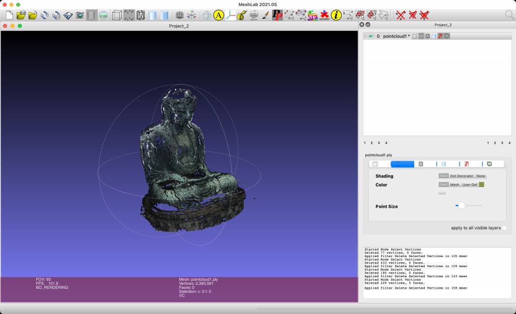
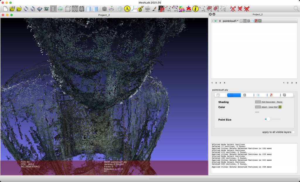
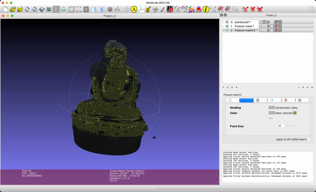
Cleaning in MeshLab
I opened the previously exported scene in MeshLab and remove stray points.
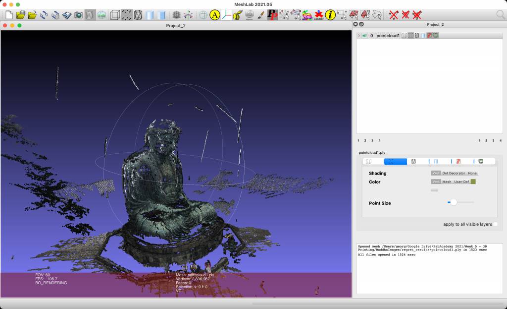
The limits of our Photogrammetry approach - and the massive size of the Great Buddha - became also clear: We simply did not have image from the top! (Challenge to future FabLab Kamakura Students: Fly a drone into the temple an take aerial photos!)
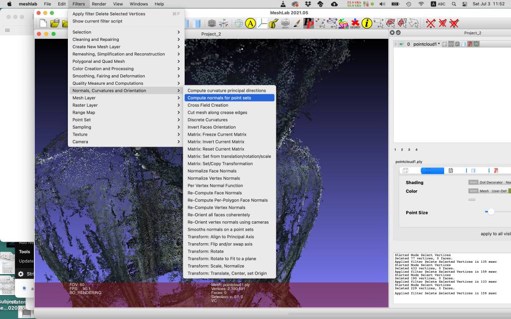
Simplification and Reconstruction
In any case, I followed the steps to turn the point cloud into a solid object.
- Filter > Normals, Curvatures and Orientation > Compute Normals for Point Set
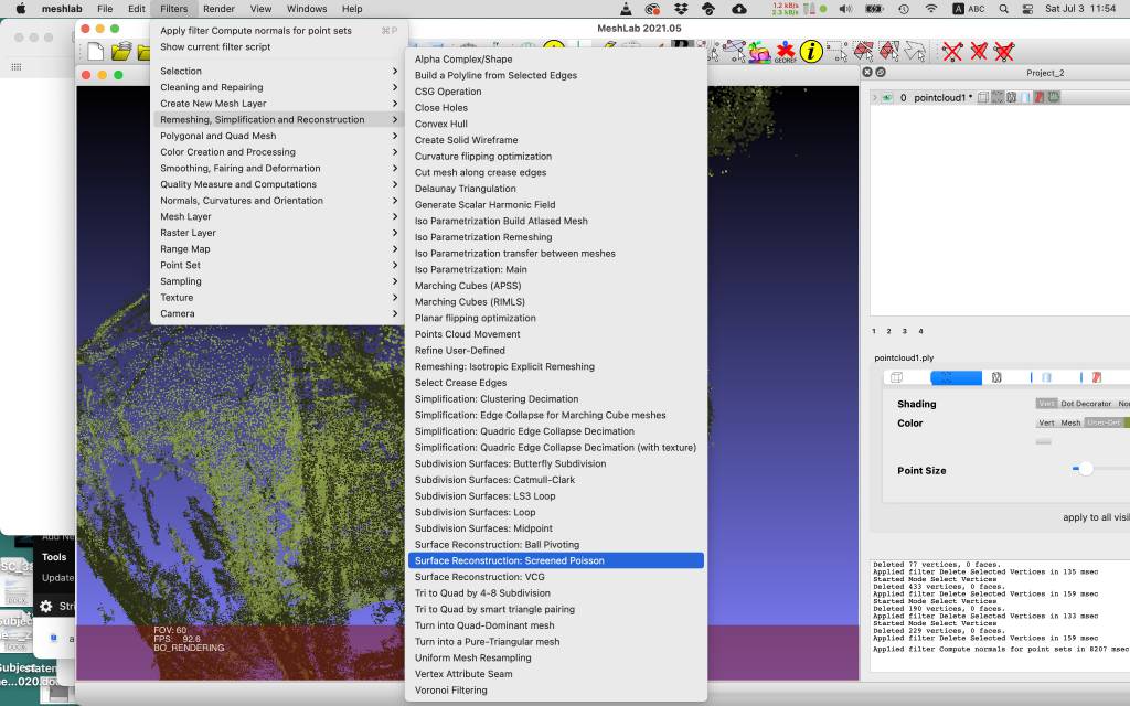
- Filter > Remeshing, Simplification and Reconstruction, Surface Reconstruction: Screened Possion
Exporting as STL
Slicing
Printing Budddhas
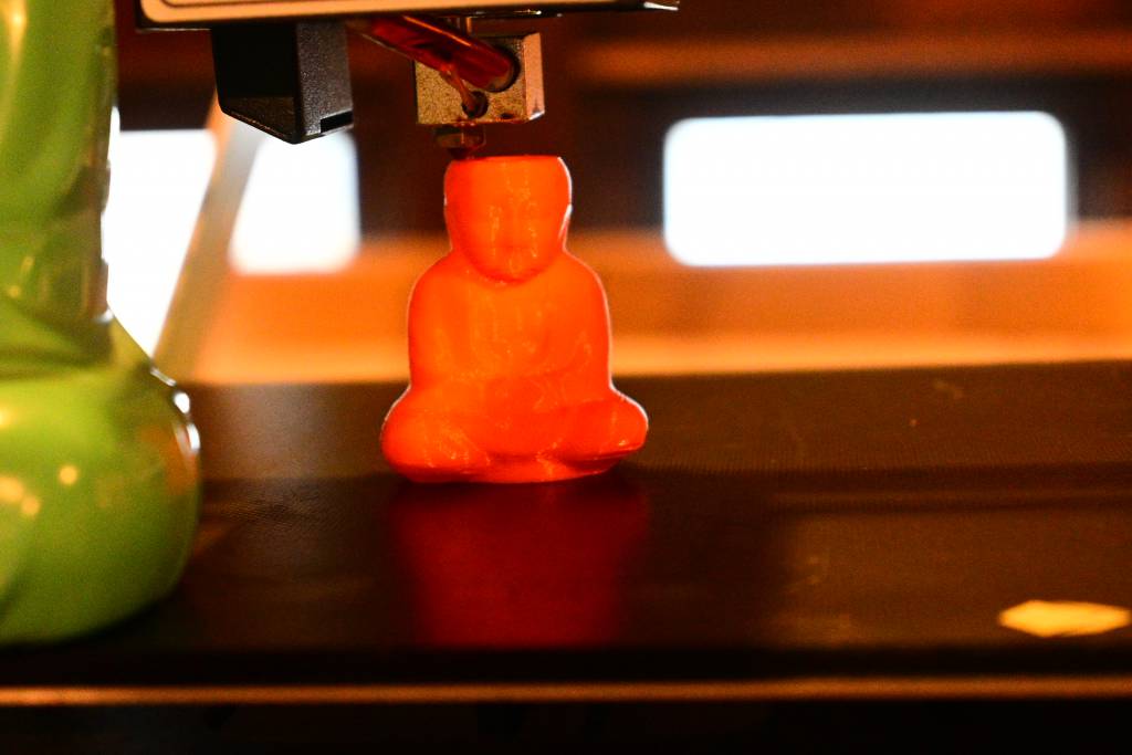
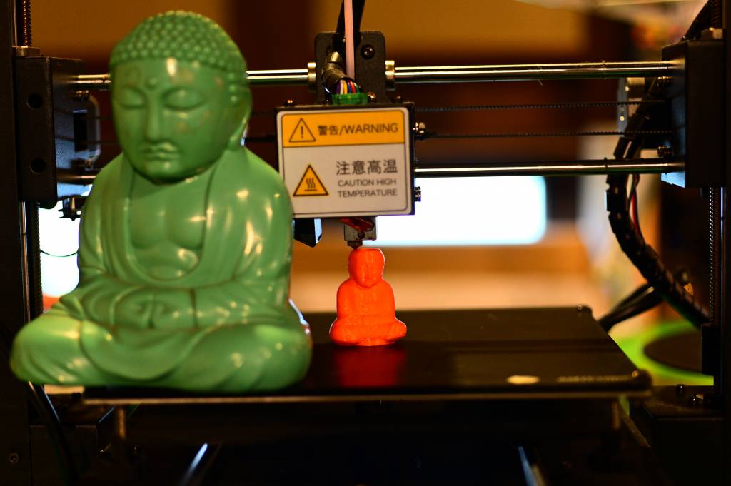
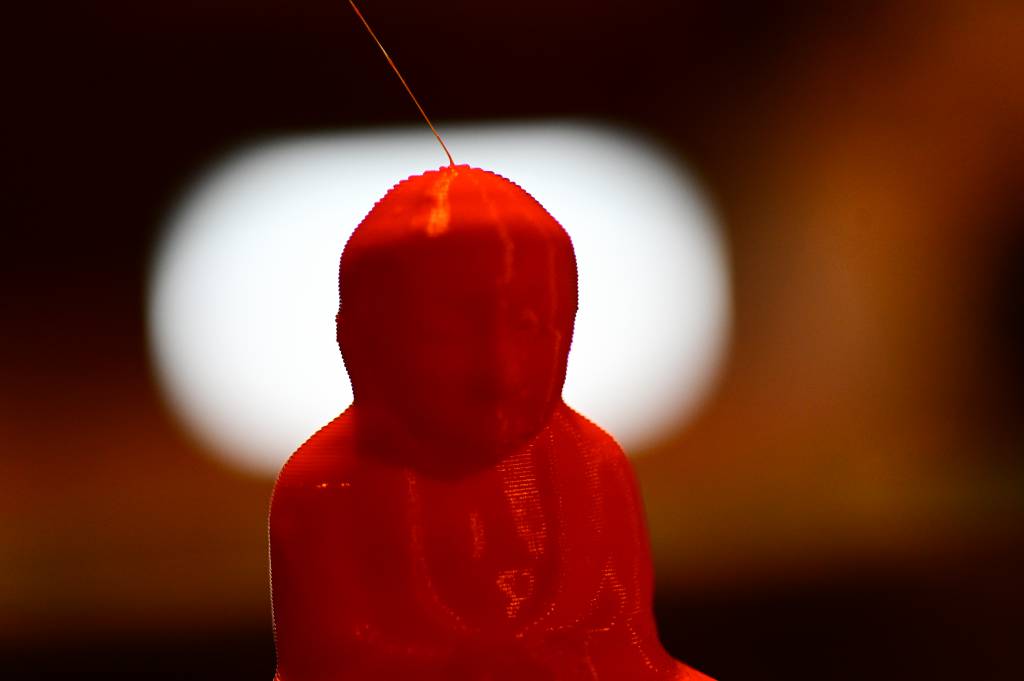
Printed Buddhas
Comparison
The clear winner is the NVIDI/Meshroom combo. Regard3D produces results, but they don't compare well with Meshroom. Also, a drone is needed to do Photogrammetry on large objects.
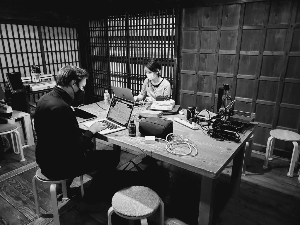
More Lab Session Images