Weekly Summary
This week was a continuation of the electronics production week. The goal was to get acquanted with the programming tool-chains for the ICs, to understand the programming process on the lowest, base level. We used the programmer we made in week 3 (FT230) to programm the circuit we made in week 6 (ATTiny3216).
Most of the time was spend to get the toolkits installed and talking to each other, the OSX security measures from Catalina and up turned out to be a big challenge, which we could eventually circumnavigate.

Blinking the ESP32
Group Assignment
The Group Assignement is to compare the performance and development workflows for other architectures. We selected to explore and investigate the BBC micro:bit and the Espressif ESP32 chip. Asano-san had a lot of fun (and made a lot of sounds and noise) with BBC micro:bit, I went through the steps to program a circuit with the Espressif ESP32, the Barduino2.0 board. Jun-san made the board and did a local documentation.

Here is the link to the Group Assignment page.
Teaser and tl;dr
ESP32 Specification
Why use the ESP32-WROOM Series? Product Page Data Sheets, User Guides, Technical Reference Manuals
- Operation Range: -40ºC to +125ºC
- Ultra-low Power Consumption (how can we test that?)
- Hybrid Wi-Fi & Bluetooth Chip
- Dual Core
- Core clock maximum freq: 240Hz
- Flash (MB) 4, 8, 16
Step 1: ESP32 Description File
- Install additional Board Manager for the ESP32 package
- Open
Ardinoo > Preferences… > Additional Board Manager - Add thttps://dl.espressif.com/dl/package_esp32_index.json to the list
- Restart the Arduino.app for the Package to appear in the Package Manager
Step 2: Install the ESP32 Software
- Search for
ESP32 - Install the package
esp32 by Espressif System. I installed version 1.0.5

Step 3: Connecting a FTDI Cable
- I am connecting with my (newly acquired) USB-to-UART FTDI cable my computer with the board.
- The shiny black side neeeds to be on top (convention)
- The red LED on top indicates that the chip is getting power.


Step 4: Echo
I downloaded the Neil's echo program and opened it in the Ardunio IDE.
A quick lsusb confirmed the serial number of the board.

Select the ESP Dev Port with your board's serial number.


After uploading the program, I got the following response:
*Uploading error:
Arduino: 1.8.13 (Mac OS X), Board: "ESP32 Dev Module, Disabled, Default 4MB with spiffs (1.2MB APP/1.5MB SPIFFS), 240MHz (WiFi/BT), QIO, 80MHz, 4MB (32Mb), 921600, None"

Sketch uses 204216 bytes (15%) of program storage space. Maximum is 1310720 bytes.
Global variables use 13476 bytes (4%) of dynamic memory, leaving 314204 bytes for local variables. Maximum is 327680 bytes.
esptool.py v3.0-dev
Serial port /dev/cu.usbserial-AQ01D57A
Connecting........_____....._____....._____....._____....._____....._____.....____An error occurred while uploading the sketch
_

A fatal error occurred: Failed to connect to ESP32: Timed out waiting for packet header
Ok, interesting.
I went into full debugging mode, searching for the error, and tried the following solution attempts to solve it:
- Holding down button while uploading: no
- Holding before connecting appears: no
- Change upload speed setting to 115200, press button after coonnecting appears: no
- Install esp32 library 1.0.4 (instead of 1.0.5): no
After a creative pause, and some re-reading of the japanese documention I realized I was making a mistake with the button/slider settings:
The board has a Reset Button (top left) and a Mode Switch (bottom right), which are involved in the choreography of uploading a program.
- Before uploading, put the switch to Programming Mode (switch to left)
- Upload the Program
- When the word 'Connecting' appears in the Arduino Console, press the Reset Button, otherwise you get the error

Uploading works! No error messages.
I open the Arduino Serial Monitor, and type a message, which should be echoed by the board...

Ok... no echos... hmmm.
Right! Run Mode. Mode Switch to right!
Pressing the Reset Button!
Echo works!


Step 5: Installing PySerial
Installing the Python-based Serial Monitor PySerial
python -m pip install pyserialGet the USB Serial Number with lsusb (TODO: make a filter script wrapping lsusb, show only external USB devices - and not all Apple internals)
lsusb
Connect the Serial Montior
python3 -m serial.tools.miniterm /dev/tty.usbserial-AQ01D57A 115200Where /dev/tty.usbserial-AQ01D57A is your device ID, and 115200 is the baud rate.
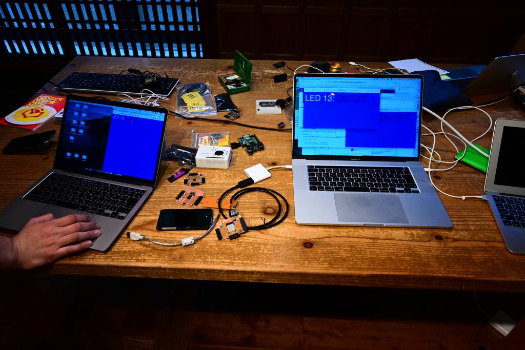
Step 5: WifiSimpleServer
The Echo was a nice, minimal start, now it's getting interesting. Turning the board into a Server, controlling the LED from a Webbrowser. The sample script comes from Espressif's GitHub Repo and can also be openend in the Arduino IDE via File > Examples > Examples for ESP32 Dev Module > Wifi > SimpleWifiServer.
I set the Kamakura Wifi-Settings in the code and defined the LED.
const char* ssid     = "yourssid";
const char* password = "yourpasswd";

#define LED_BUILTIN 13
and doing the usual Switch-Left, Upload, Reset, Switch-Right route started the program.
In the Serial Monitor the IP Address for the ESP32 is being shown:
rst:0x1 (POWERON_RESET),boot:0x13 (SPI_FAST_FLASH_BOOT)
ets Jun  8 2016 00:22:57

rst:0x10 (RTCWDT_RTC_RESET),boot:0x13 (SPI_FAST_FLASH_BOOT)
configsip: 0, SPIWP:0xee
clk_drv:0x00,q_drv:0x00,d_drv:0x00,cs0_drv:0x00,hd_drv:0x00,wp_drv:0x00
mode:DIO, clock div:1
load:0x3fff0018,len:4
load:0x3fff001c,len:1216
ho 0 tail 12 room 4
load:0x40078000,len:10944
load:0x40080400,len:6388
entry 0x400806b4

Connecting to fablabkamakura_wifi
.....
WiFi connected.
IP address:
192.168.1.45
Pointing a browser to the local IP Adress shows the basic site that has been created by the ESP32:
client.println("HTTP/1.1 200 OK");
client.println("Content-type:text/html");
client.print("Click <a href=\"/H\">here</a> to turn the LED on pin 13 on.<br>");
client.print("Click <a href=\"/L\">here</a> to turn the LED on pin 13 off.<br>");
Going to 192.168.1.45/H turns the LED on, going to 192.168.1.45/L turns it off.
I wanted to know, if applying some CSS styles would also work:
client.println("HTTP/1.1 200 OK");
client.println("Content-type:text/html");
client.print("<style>body { background: #00f; color: #fff; font: 50px Helvetica, sans-serif; } a.hover { color: #0f0; }</style>");
// the content of the HTTP response follows the header:
client.print("LED 13: ");
client.print("<a href=\"/H\">ON</a> <a href=\"/L\">OFF</a>");
Hmmm. Not quite.
How about adding <html><body>?
client.println("HTTP/1.1 200 OK");
client.println("Content-type:text/html");
client.print("<html><body>");
client.print("<style>body { background: #00f; color: #fff; font: 50px Helvetica, sans-serif; } a.hover { color: #0f0; }</style>");
// the content of the HTTP response follows the header:
client.print("LED 13: ");
client.print("<a href=\"/H\">ON</a> <a href=\"/L\">OFF</a>");
Also works when connecting more than one browser!
My modified SimpleWifiServer is also linked in the reference section below.
More details at the Group Assignment page.
Learning Outcomes
I was positively impressed by both the capapilities and possibities of both the BBC micro:bit and the ESP32. It was a very, very satisfying moment to get the webserver to run on the ESP32 and control the LED via a website.
I only caught some glimpses of the BBC micro:bit - and the Scratch programming enviroment for kids. By chance, my 11-year old also asked me this week how to do programming "with blocks, and not that strange text that you are always doing." Turns out they are starting to learn Scratch in school, and as the BBC micro:bit can also be programmed in Scratch, I am getting a BBC micro:bit for her.
And I will most likely use a ESP32 for my Final Project.
Individual Assignment
- read a microcontroller data sheet
- program your board to do something,
- with as many different programming languages
- and programming environments as possible
The goal is to program our chip - the ATTiny3216 not only with the Arduino workflow, but also directly in C.

Following the instructions from Nagano-san and the local class page we started by installing the drivers, and toolchains.
Reading the ATTiny3216 Data Sheet
I read the data sheet of the ATTiny3216, my highlighted and annotated PDF.
What is the PTC - Peripheral Touch Controller?
The ATTiny3216 has an on-board Peripheral Touch Controller, what exactly is that?

Internal Temperature Sensor
The ATTiny also has an internal temperature sensor. The ADC can be configured to read the TEMPREF. I am curious how the internal temperature compares to a dedicated temperature sensor.
Nomenclature
Nice of Microchip to explain their nomenclature. Next Chips will be probably be called: (my suggestions)
- ATTiny 3226 (32K Memory, Series 2, 6 = 20pins)
- ATTiny 6416 (64K Memory, Series 1, 6 = 20pins)
- ATTiny 12816 (128K Memory, Series 1, 6 = 20pins)
- ATTiny 25626 (256K Memory, Series 2, 6 = 20pins)
- ATTiny 3236 (32K Memory, Series 3, 6 = 20pins)
Unique ID
Each ATTiny has a unique serial number. Good to know. Curious if this can be used to make ad-hoc connections, where the main/secondary structure is not defined beforehand.
Installation of the Toolchain
Before we can start programming the ATTiny3216, we need to install driver and utilities:
-
FDTI Drivers https://ftdichip.com/drivers/vcp-drivers/, for the macOS, download the FTDIUSBSerialDriver_v2_4_4.dmg file
-
MicroChip Toolchain: https://www.microchip.com/en-us/development-tools-tools-and-software/gcc-compilers-avr-and-arm
I downloaded the AVR 8-bit Toolchain 3.6.2 - Mac OS X 64-bit, expanded it and put in into a new folder I called avr in my Documents folder. Not sure that's the best place for it.
- ATtiny_DFP atpack (what does atpack actually mean?): http://packs.download.atmel.com
I downloaded the file for the ATTiny series: Atmel.ATtiny_DFP.1.9.337, for some reason the file has an .atpack ending, I changed it to .zip, unzipped it, and also put it into my air folder.
- We also need the pyupdi interface, install it with:
pip3 install https://github.com/mraardvark/pyupdi/archive/master.zip
Adding avr to the $PATH
On macOS the default shell is now zsh, we need to add the avr toolchain to the $PATH. Make a new file, call it .zshenv and add the following line. (reflecting the location for your avr toolchain.)
export PATH=/Users/georg/Documents/avr/avr8-gnu-toolchain-darwin_x86_64/bin:$PATHBlink
One of simplest Hello World programs is to blink a LED.
button and led are the pins, pinMode sets the Pins to either OUTPUT or INPUT. In the infinity loop, the led is on for 500ms, then off for 500ms, and so on...∞
const int button = 0;
const int led = 16;

void setup() {
  pinMode(button, INPUT);
  pinMode(led, OUTPUT);
}

void loop() {
  digitalWrite(led, HIGH);
  delay(500);
  digitalWrite(led, LOW);
  delay(500);
}
That's nice. But we can do better.
Button-Timed Blink
Let's make use of the button and correlate the time intervals of the blinks with the time from buttonDown to buttonUp.

const int button = 0;
const int led = 16;
int buttonState = false;
int ledState = HIGH;
int buttonDownTime = 0;
bool buttonDownBit = false;
unsigned long currentTime = 0;
unsigned long previousTime = 0;
unsigned long delayTime = 100;

void setup() {
  pinMode(button, INPUT);
  pinMode(led, OUTPUT);
}

void loop() {
  getDelay();
  blink();
  delay(1);
}

void getDelay() {
  // get buttonDownTim
  buttonState = digitalRead(button);
  // buttonState LOW means button is pressed
  if ((buttonState == LOW) && (buttonDownBit == false)) {
    buttonDownTime = millis();
    buttonDownBit = true;
  }
  if ((buttonState == HIGH) && (buttonDownBit == true)) {
    delayTime = millis() - buttonDownTime;
    buttonDownBit = false;
  }
}

void blink() {
  currentTime = millis();
  if ((currentTime - previousTime) >= delayTime) {
    ledState = (ledState == LOW) ? HIGH : LOW;
    digitalWrite(led, ledState);
    previousTime = currentTime;
  }
}
int buttonDownTime cause the timer to run over after 216 (65536) ms, as ints are stored as 2 bytes, 1 byte is 8bit, 2 bytes = 16bit, 216, 65536. Which meant the program stopped working after 65 seconds.
int buttonDownTime = 0;
unsigned long currentTime = 0;
unsigned long previousTime = 0;
unsigned long delayTime = 100;
buttonDownTime also need to be of unsigned long type. unsigned long is 4 bytes, 232, 4294967296ms or about 49.71 days. (or ~1193 hours, ~71582 minutes or 4294967 seconds). The millis() reference confirms this.
unsigned long buttonDownTime = 0;
unsigned long currentTime = 0;
unsigned long previousTime = 0;
unsigned long delayTime = 100;To be absolutely sure - in case we want to run the blink program for more than 50 days, I added a check for the run over.
...
    if (millis() < buttonDownTime) {
      buttonDownTime = buttonDownTime - 2**32;
    }
...


AVR-GCC Tool-chain
I started with the traditional blink program, kindly made available by Neil. Unlike an .ino file, your need a .c file and a make file.
- http://academy.cba.mit.edu/classes/embedded_programming/t412/hello.t412.3.blink.c
- http://academy.cba.mit.edu/classes/embedded_programming/t412/hello.t412.3.blink.make
The avr tools are in the $PATH, but we need to make some changes to the make file:
DEVICE = tiny3216
PACK = ~/Documents/avr/Atmel.ATtiny_DFP.1.9.337
PORT = /dev/tty.usbserial-D307OEPA
The DEVICE is out tiny3216, PACK is the path to the Atmel pack, and PORT is the address of the device. This is on macOS, your paths will be different.

Nagano-san made a nice overview slide:

Once the paths are set, the next steps are to make the make files:
make -f hello.t412.3.blink.make
make -f hello.t412.3.blink.make pyupdi
And that's where things started to get interesting

After some searches, I came across this article, which described a way to take the program out of quarantine.
Doing a which avr-gcc gave me the path of the program.
$ xattr -d -r com.apple.quarantine /path/to/avr-gcc
$ spctl --add --label "Approved" /path/to/avr-gcc
Ok, running make again.
Ok, another security problem.

This time a which cc1 did not turn up results, I found it later in the avr folder.
Doing the same routine...
$ xattr -d -r com.apple.quarantine /path/to/cc1
$ spctl --add --label "Approved" /path/to/cc1
... did not have any effect.
Really stuck.
I considered switching to a pre-Catalina OS.
One final move, one final thought. Maybe it's possible to approve the whole bin directory, and not only a single program?
$ xattr -d -r com.apple.quarantine /path/to/avr8-gnu-toolchain-darwin_x86_64/bin
$ spctl --add --label "Approved" /path/to/avr8-gnu-toolchain-darwin_x86_64/bin
And that worked!


Blinc (Blink with a C)
I also rewrote Neil's Blink C program, to look a bit more Arduino-y.
#include <avr/io.h>
#include <util/delay.h>

#define set(port,pin) (port |= pin) // set port pin
#define clear(port,pin) (port &= (~pin)) // clear port pin

#define LED_DIR VPORTA.DIR
#define LED_OUT VPORTA.OUT
#define LED_PIN PIN3_bm     // bm -> bitmask

int main(void) {
  CPU_CCP = CCP_IOREG_gc; // unprotect clock
  CLKCTRL.MCLKCTRLB = 0; // turn off prescalar (20 MHz)
  set(LED_DIR,LED_PIN);
  // start loop
  loop();
}

void loop(void) {
  while (1) {
    blink(25, 50);
  }
}

void blink(int a, int b) {
  set(LED_OUT,LED_PIN);
  _delay_ms(a);
  clear(LED_OUT,LED_PIN);
  _delay_ms(b);
}
/Users/georg/Documents/avr/avr8-gnu-toolchain-darwin_x86_64/avr/include/avr/io.h:623:6: warning: #warning "device type not defined" [-Wcpp]
 #    warning "device type not defined"
      ^
blinc_3216.c: In function 'main':
blinc_3216.c:27:3: error: 'CPU_CCP' undeclared (first use in this function)
   CPU_CCP = CCP_IOREG_gc; // unprotect clock
   ^
blinc_3216.c:27:3: note: each undeclared identifier is reported only once for each function it appears in
blinc_3216.c:27:13: error: 'CCP_IOREG_gc' undeclared (first use in this function)
   CPU_CCP = CCP_IOREG_gc; // unprotect clock
...
make: *** [blinc_3216.out] Error 1
Thats strange. It was working before... Hmm..
Let's look at the make file again:
PROJECT=blinc_3216
SOURCES=$(PROJECT).c
DEVICE = tiny3216
MMCU=at$(DEVICE)
F_CPU = 20000000
PACK = ~/Documents/avr/Atmel.ATtiny_DFP.1.9.337
PORT = /dev/tty.usbserial-D307OEPA
BAUD = 57600

CFLAGS=-mmcu=$(MMCU) -Wall -Os -DF_CPU=$(F_CPU)

$(PROJECT).hex: $(PROJECT).out
    avr-objcopy -O ihex $(PROJECT).out $(PROJECT).hex;\
    avr-size --mcu=$(MMCU) --format=avr $(PROJECT).out

$(PROJECT).out: $(SOURCES)
    avr-gcc $(CFLAGS) -I./ -I$(PACK)/include -B$(PACK)/gcc/dev/$(MMCU) -o $(PROJECT).out $(SOURCES)

pyupdi: $(PROJECT).hex
    pyupdi -d $(DEVICE) -c $(PORT) -b $(BAUD) -v -f $(PROJECT).hex
-
PROJECT and DEVICE names are ok.
-
PORT is also ok.
-
Hmmm.
-
Maybe the PACK path?
-
What if I change the relative path to an absolute path?
...
PACK = /Users/georg/Documents/avr/Atmel.ATtiny_DFP.1.9.337
...Ok, that's better, but not quite.
__builtin_avr_delay_cycles(__ticks_dc);It looks like _delay_ms() expects a constant integer, and therefore it fails. Removing the passed ints solved this.
avr-gcc also like to have it's functions declared in advance:
...
void loop(void);
void blink(void);
...
Then it does not complain.
#include <avr/io.h>
#include <util/delay.h>

#define set(port,pin) (port |= pin) // set port pin
#define clear(port,pin) (port &= (~pin)) // clear port pin

#define LED_DIR VPORTA.DIR
#define LED_OUT VPORTA.OUT
#define LED_PIN PIN3_bm

void loop(void);
void blink(void);

int main(void) {
  CPU_CCP = CCP_IOREG_gc;
  CLKCTRL.MCLKCTRLB = 0;
  set(LED_DIR,LED_PIN);
  // start loop
  loop();
}

void loop(void) {
  while (1) {
    blink();
  }
}

void blink() {
  set(LED_OUT,LED_PIN);
  _delay_ms(25);
  clear(LED_OUT,LED_PIN);
  _delay_ms(50);
}
make -f blinc_3216.make
avr-gcc -mmcu=attiny3216 -Wall -Os -DF_CPU=20000000 -I./ -I/Users/georg/Documents/avr/Atmel.ATtiny_DFP.1.9.337/include -B/Users/georg/Documents/avr/Atmel.ATtiny_DFP.1.9.337/gcc/dev/attiny3216 -o blinc_3216.out blinc_3216.c
avr-objcopy -O ihex blinc_3216.out blinc_3216.hex;\
avr-size --mcu=attiny3216 --format=avr blinc_3216.out
AVR Memory Usage
----------------
Device: Unknown
Program: 216 bytes
(.text + .data + .bootloader)
Data: 0 bytes
(.data + .bss + .noinit)For make, hex, and out files, see the Files Section below.
Conclusion
Programming directly in C has the benefit of faster uploads - as only the needed libraries have to be transferred. Using the Arduino IDE and environment has the benefit of nicer and more comprehensible error messages.
If you absolutely know what you want your chip to do, and execution speed is critically important for you and your project, and you don't mind wading through arcane error messages, then please use C/C++.
If you want to explore and play with the code, use the Arduino IDE.
Hero Image & Video
Hero Image
