Weekly Summary
This week's assignments is to get acquainted with the lab's vinylcutter and lasercutter, and create a parametric construction kit. On Saturday we did the group work, and the vinyl cutting, on Sunday I used some of the free working time to do additional lasercutting.
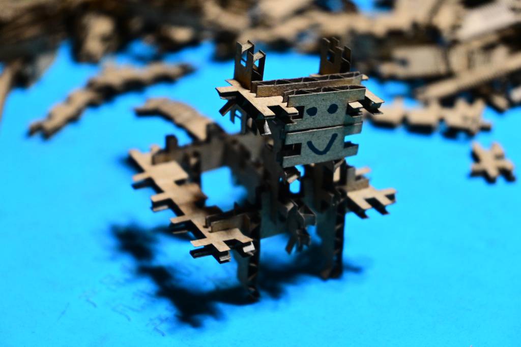
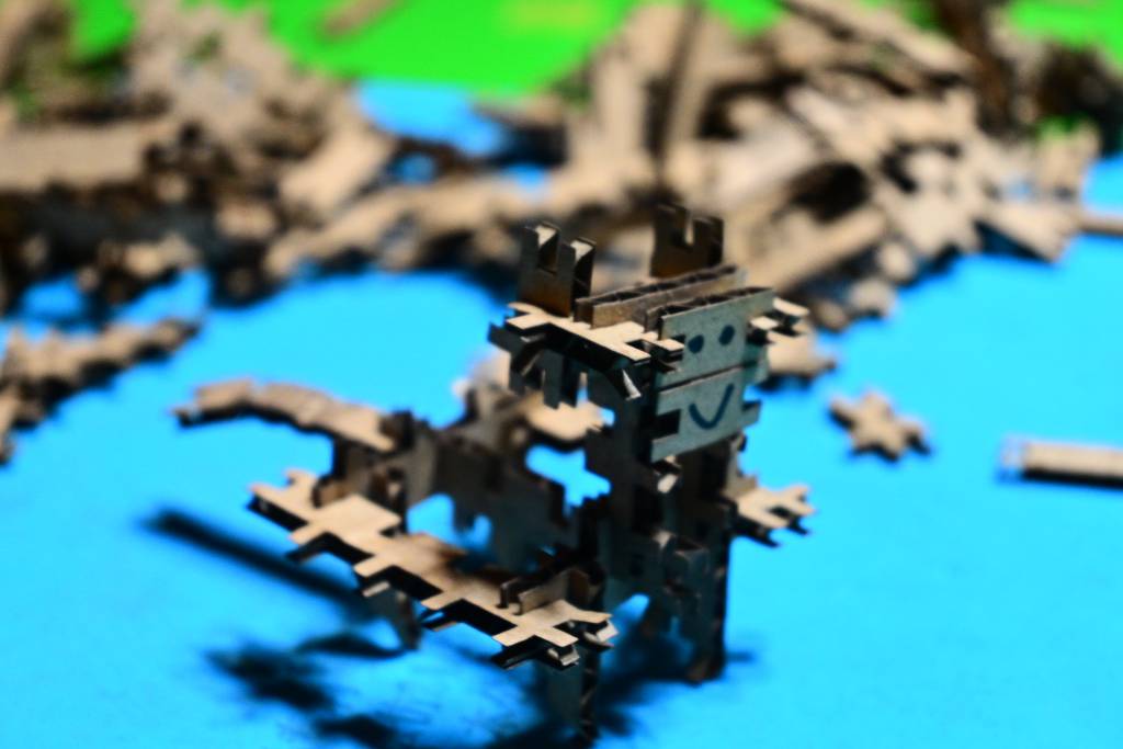
- I designed and cut a Wasteless Parametric Construction Kit, the challenge was to make a variety of pieces that did not produce any left-overs from a cardboard sheet.
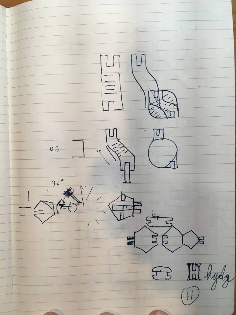
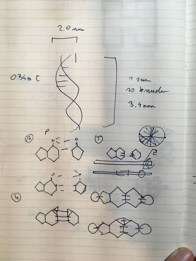
I was also curious to make a Cardboard DNA Model and experiment with DIY Microfluids, but ran out of lab time. I will leave the sketches and ideas in the Appendix. I revisited the DIY Microfluids in the Wildcard Week.
- I designed (but not yet cut) a Cardboard DNA Model, that could model the A, B and Z confirmations of DNA - and clearly show the Hydrogen Bonds between the bases.
- I used to Vinyl Cutter to cut patterns for DIY Microfluids Device (also used the Lasercutter to cut the Acrylic for the top and and bottom parts)
Assignment Work Plan
The Parametric Design Kit (let's call it PDK from now) is the Hello World of lasercutting. It has probably been made thousands (tens-of-thousands?) times alone at the HTMAA & FabAcademy sessions, but the goal is not to create some novel, but to learn how to use the lasercutter. Having said that, it is - like all the assignments - a chance to show creativity, do something exciting, and not follow the path of least resistance.
Timetable
I am planning to do the following this week, starting to internalise SSTM:
- Thursday: 3 hours, Sketches & Designs for PCKs
- Friday: 4 hours: Continuous with Learning Fusion, Parametric Modeling, More Sketches
- Saturday: 10:00 - 18:00 Lab Session in Kamakura, Cutting, Re-designing
- Sunday: 14:00 - 16:00 Free Work Sesson in Kamakura, More Cutting
- Monday: 2 hours, Documenting, Writing
- Tuesday: 2 hours, Documenting
- Wednesday: 5 hours, Documenting, Website Design & Code Updates Total: 26 hours
Group Assignment
The group assignment is to characterize your lasercutter's focus, power, speed, rate, kerf, joint clearance and types.
The group assignment is to look and experiment with the different options of the lasercutter - and the material-of-choice, which in case for the parametric construction kit was 3mm corrugated cardboard. Full documentation of our successes - and failures - at our FabLab Kamakura Group Page.
Individual Assignments
- cut something on the vinylcutter
- design, lasercut, and document a parametric construction kit,
- accounting for the lasercutter kerf,
- which can be assembled in multiple ways,
- and for extra credit include elements that aren't flat
Since I started my recent journey in 3D modeling - and now that the cloud-save problems are resolved, thanks to the personal support from Autodesk - I am continuing to use and learn Fusion 360 for making the parametric construction kit.
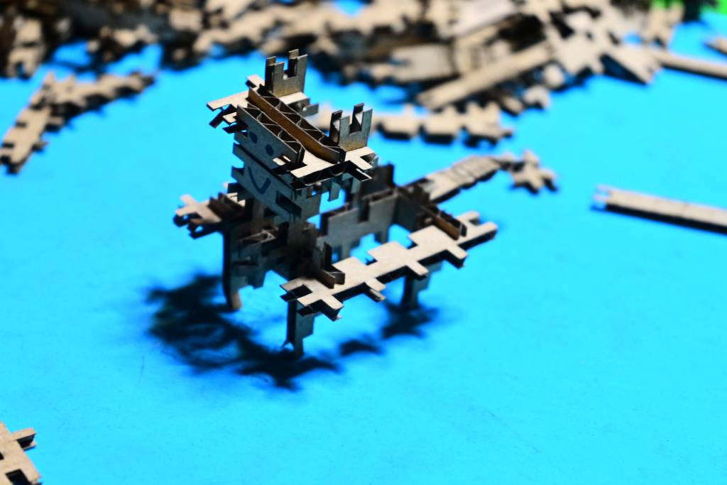
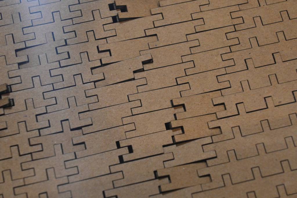
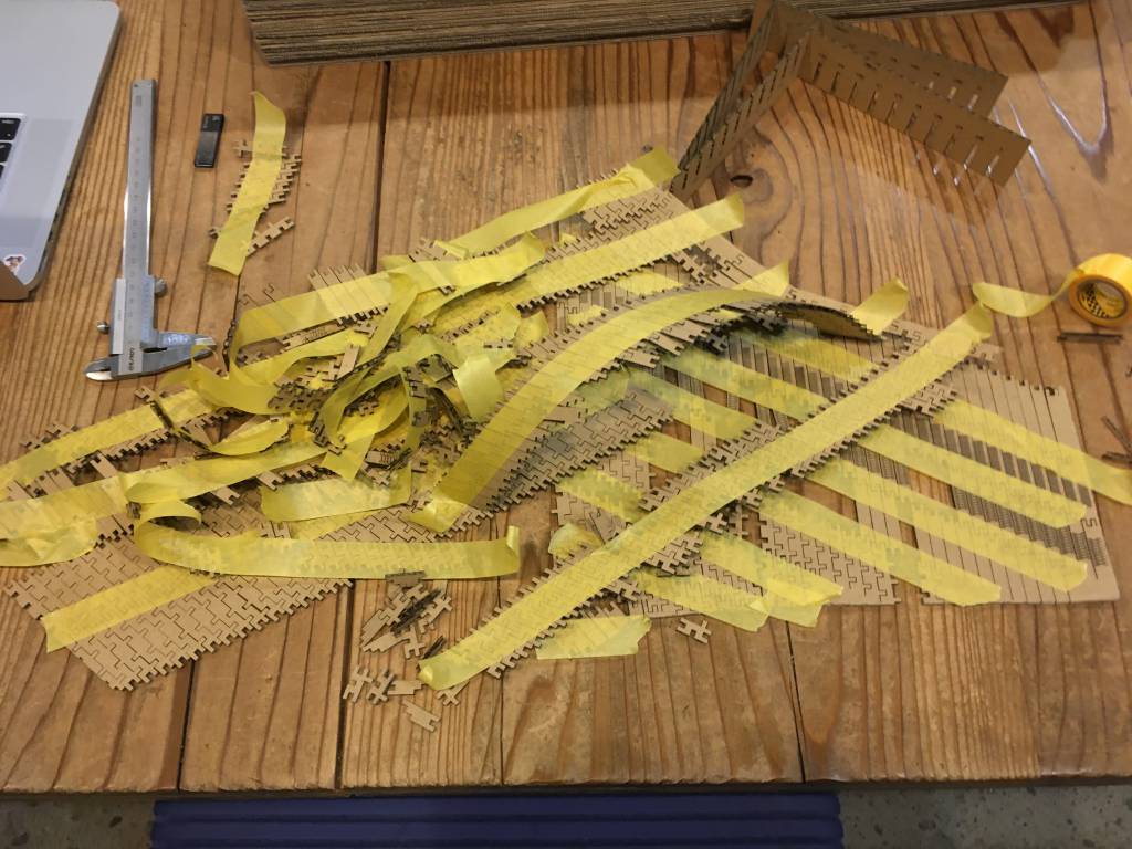
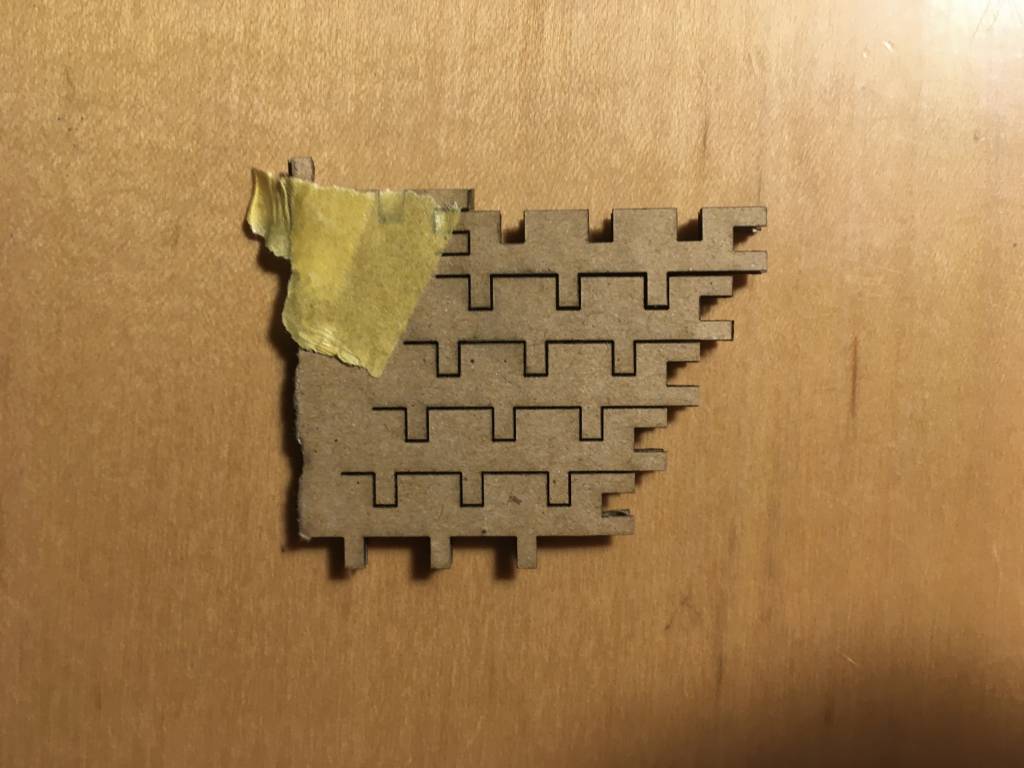
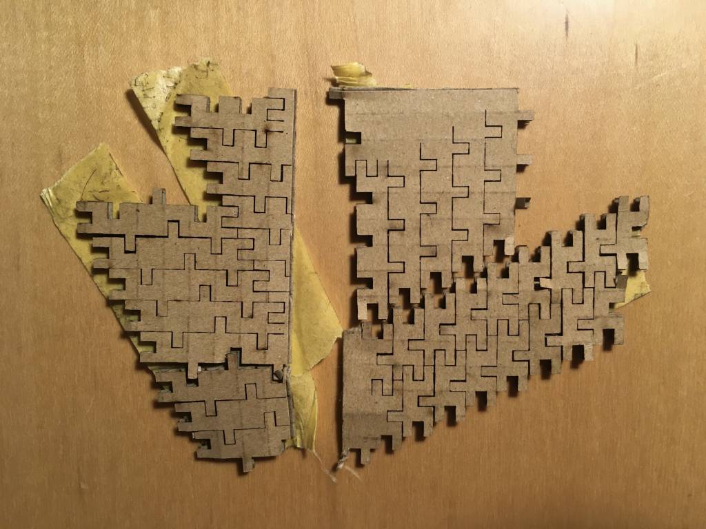
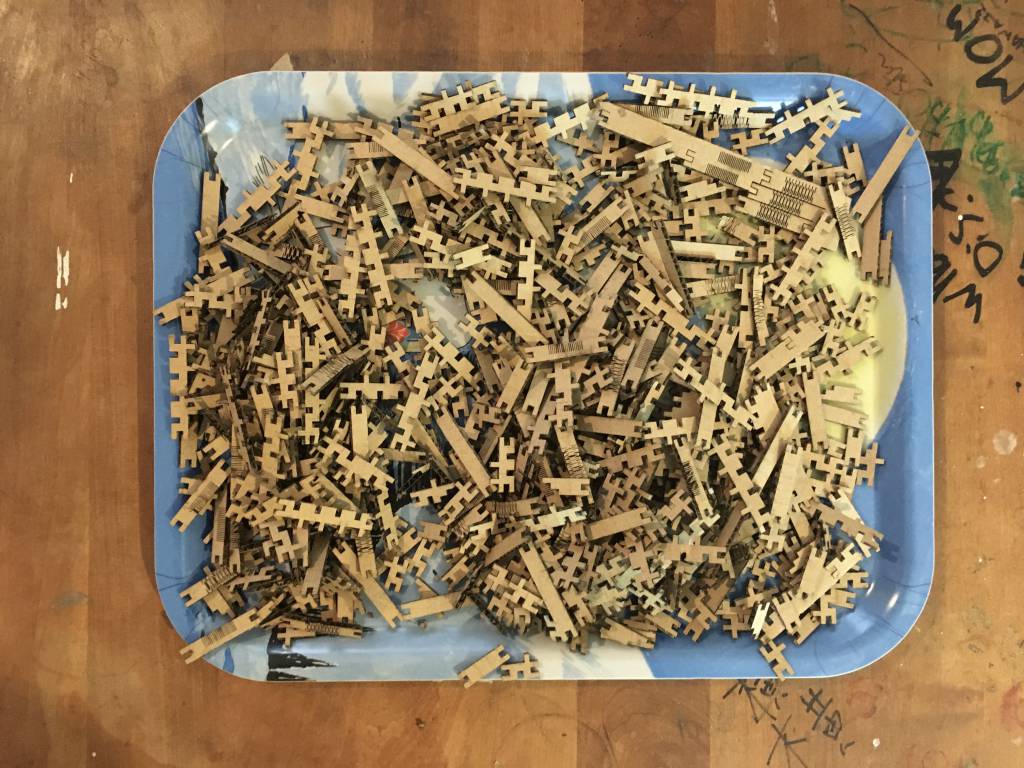
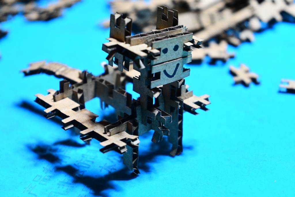
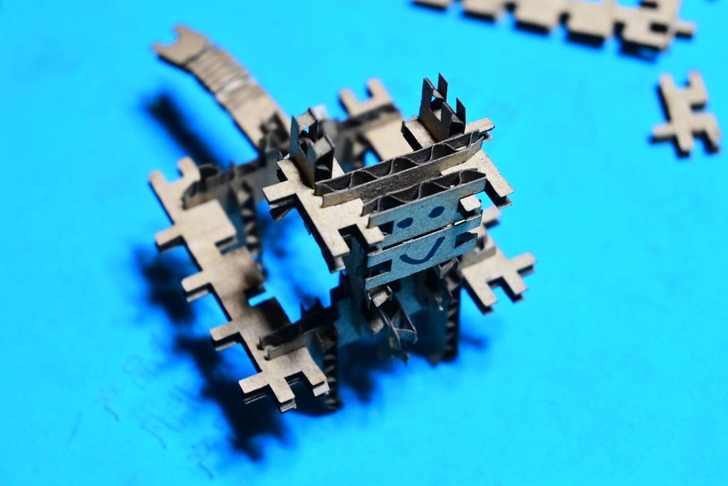
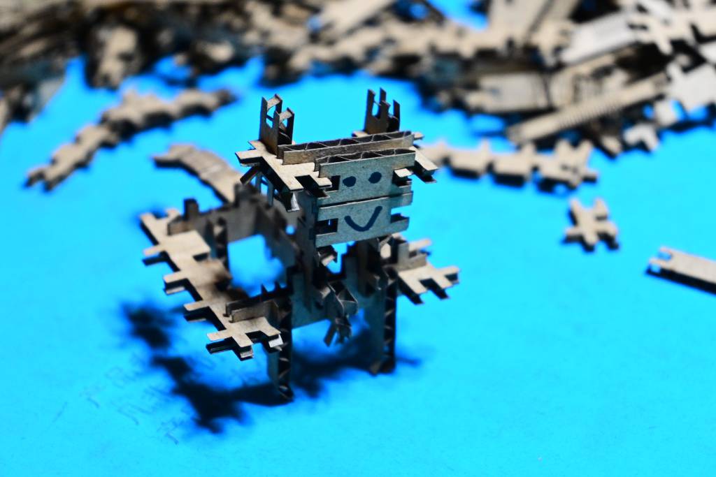
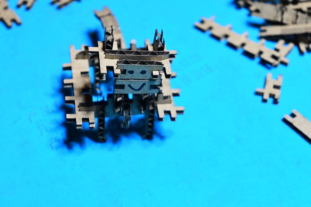
Wasteless Parametric Construction Kit
Background, Idea & Motivation
Lasercutters are great tools to cut sheet materials into exact pieces - once you accounted for the kerf. While it creates useful, desired, postive forms are created, also a lot waste, or negative forms are created - and usually thrown away, or added to the local material library, if they are still large enough.
For this exercise, I want to make a kit, that does not distinguish between negative and positive forms, a kit where all the cut pieces could be used for construction, a no waste, or wasteless Parametric Construction Kit
Plane Tiling Euclidean plane tilings by convex regular polygons have a long history, the challenge is to account for the connector and the kerf.
Sketch
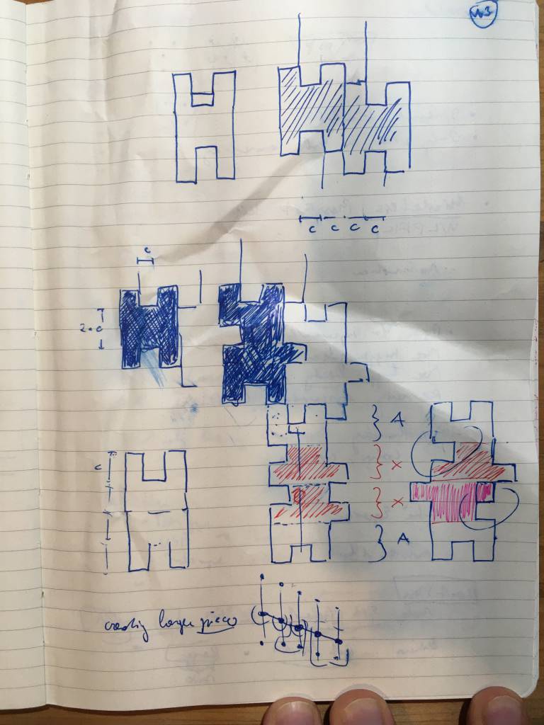
Here is a sketch that show the early developments and variations.
Design Visualization in Illustrator
Before moving to parametric design, I pre-visualized the sketches in Illustrator to get a better understanding of the tiling behaviour and the design limitations.
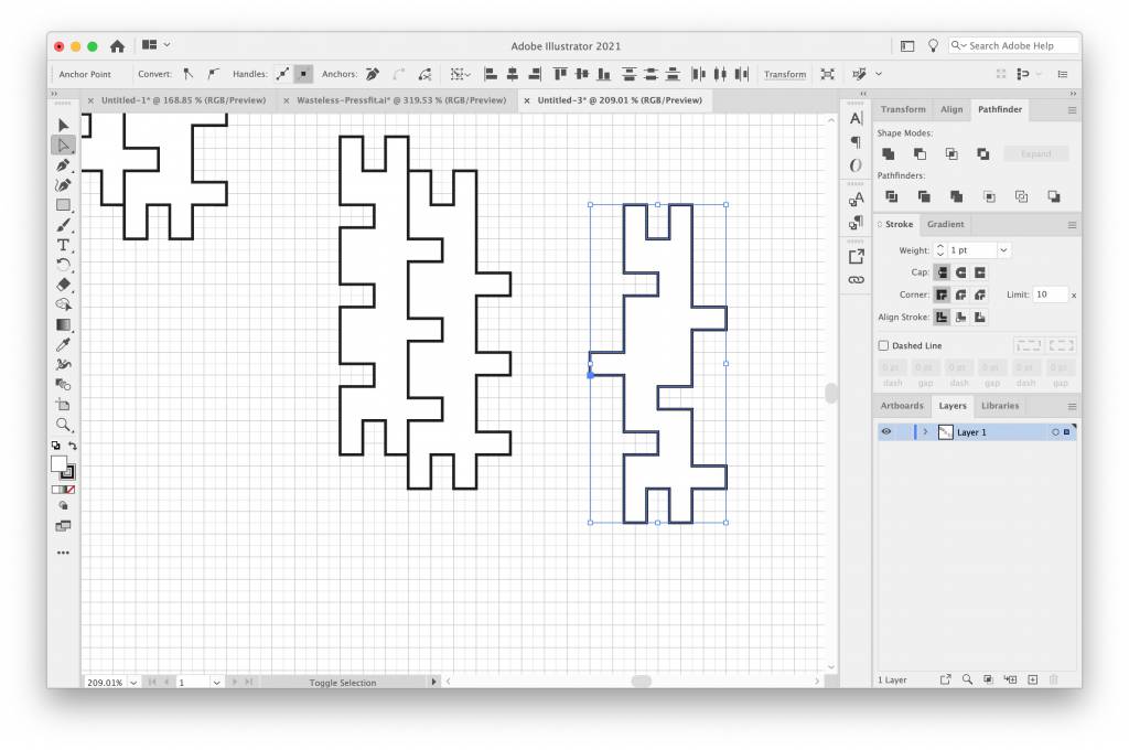
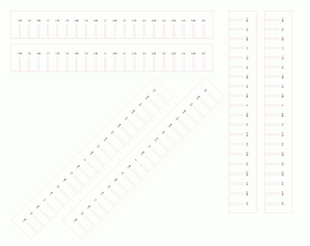
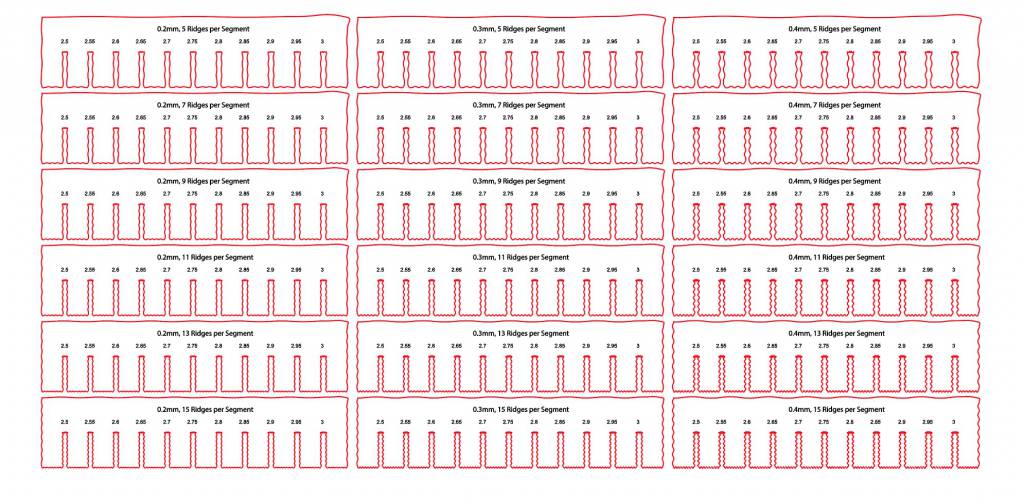
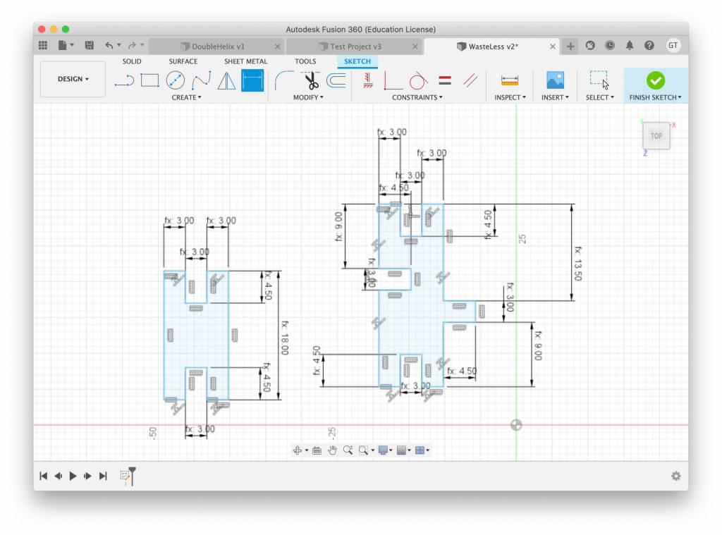
Parametric Design in Fusion 360
In Fusion 360 I defined 2 user parameter, which are driving our designs:
- thickness: Thickness of the Board
- slotlength: Length of the Slot
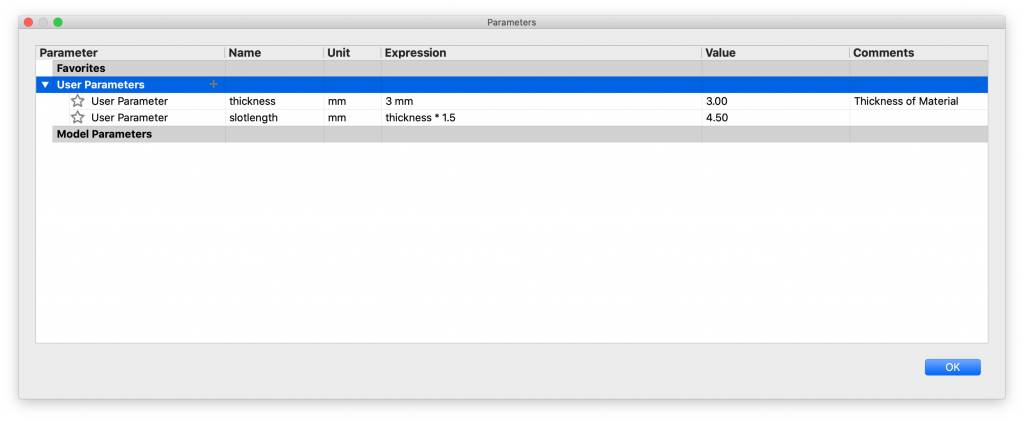
No Chamfers? I know, I know: Slots need chamfers. Giving the we are working with both the negative and positive forms, and are constraining ourselves not to produce waste, I was curious if we could actually create chamfers for both negative and positive forms.
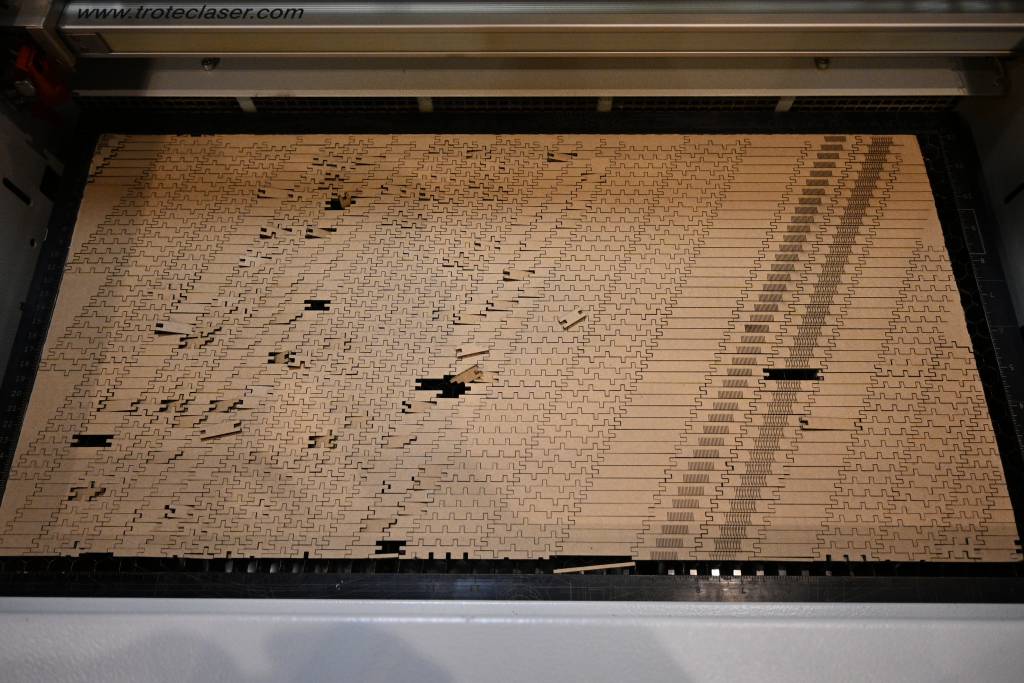
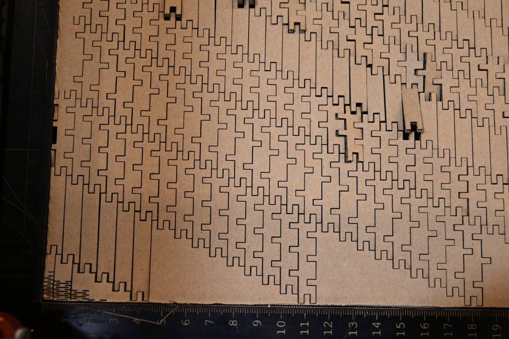
Preparing Output Lasercutting
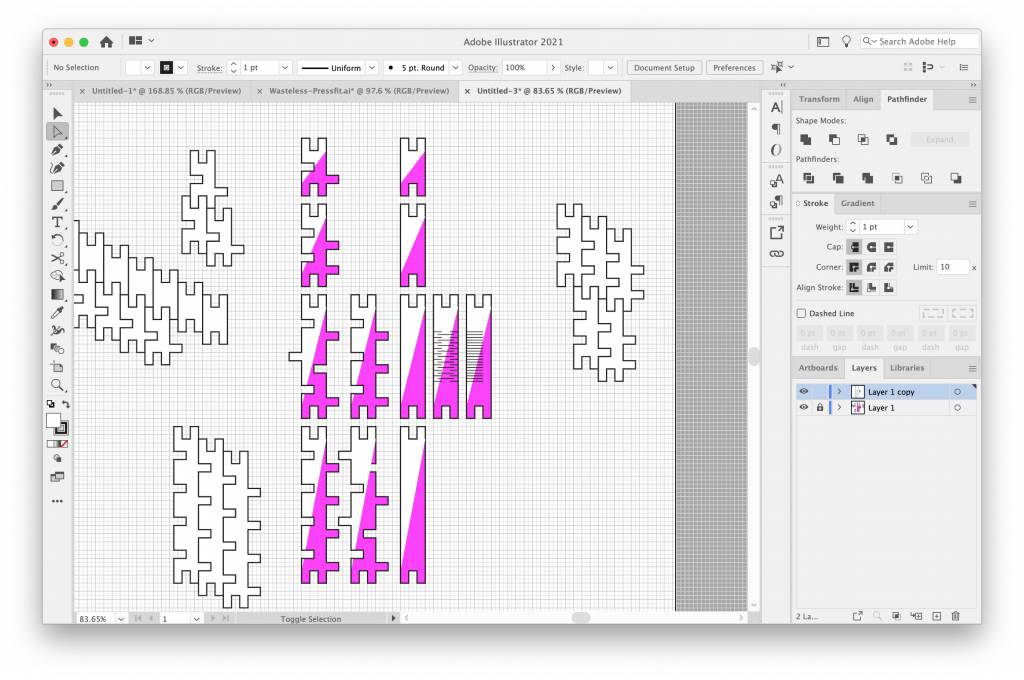
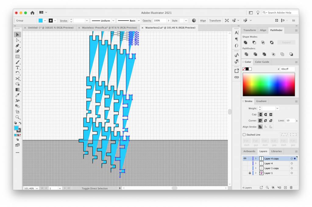
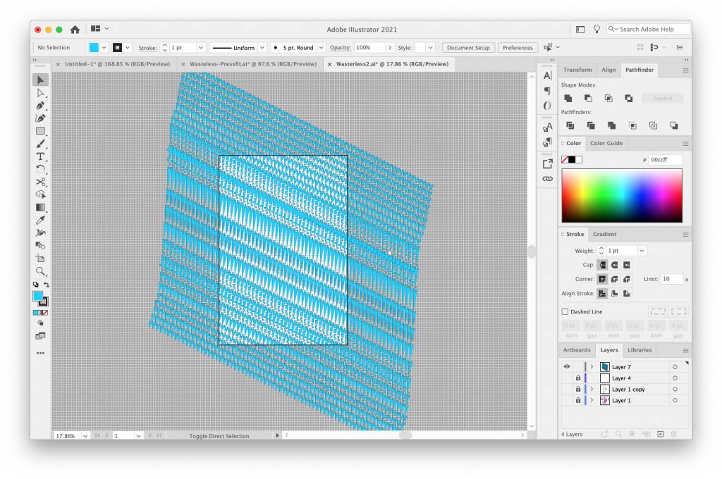
Challenge: Tiling
The challenge I spend probably most time, was how to tile the patterns effectively - and programmatically. I
Challenge: No Double Cuts
When aligning two cut pieces so that the share a common line, you get two lines in the same space, which the lasercutter would then cut twice. I manually remove edges from the parts before tiling, making sure, each line is only cut once. If there is a more elegant solution to removing double passes, please do let me!
Challenge: Bendy Bits
I also designed some bendy bits that could either bend sideways or vertical. The problem was that I used too small pieces for the bending experiment, the corrugated structure of the cardboard was interferring with the bending cuts. Next time use bigger pieces for bending.
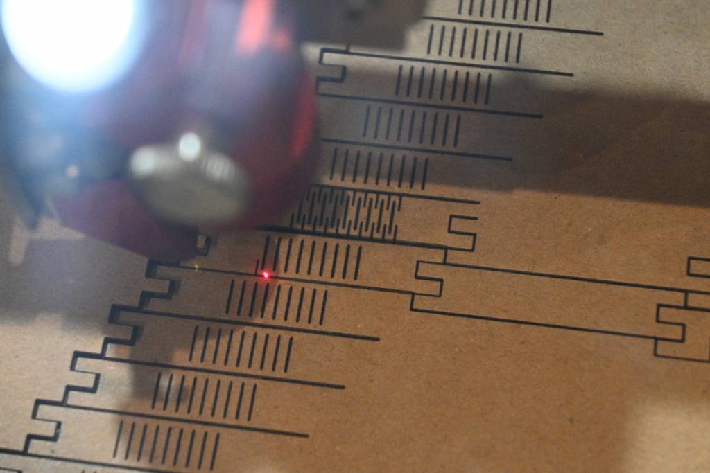
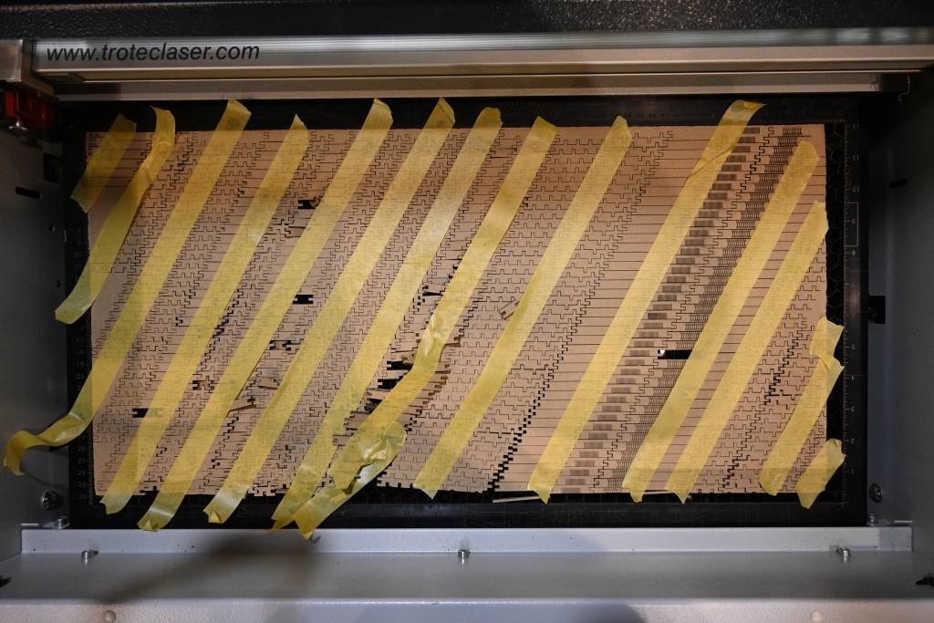
Lasercutting
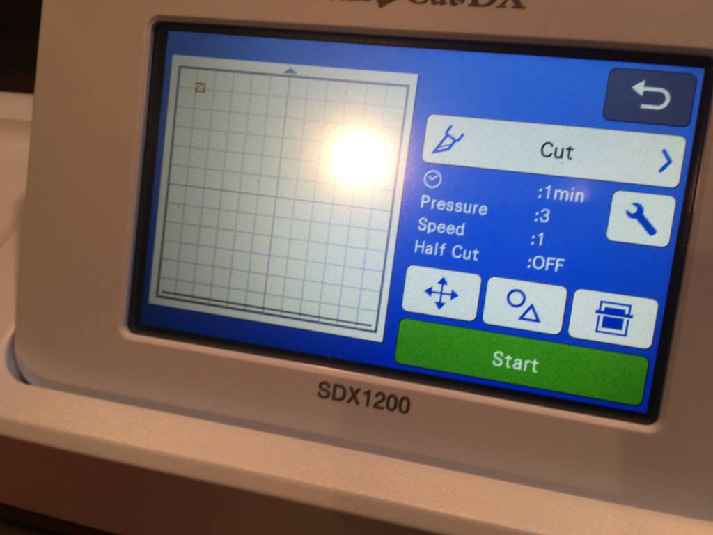
Lasercutting was done with the parameter we established during the group work:
Power: 85%
Speed: 2.0
Frequency: 1000
Why not 100%? 2
Results
Hero
Hero Videos
Hero Images
Learning Outcomes and Observations
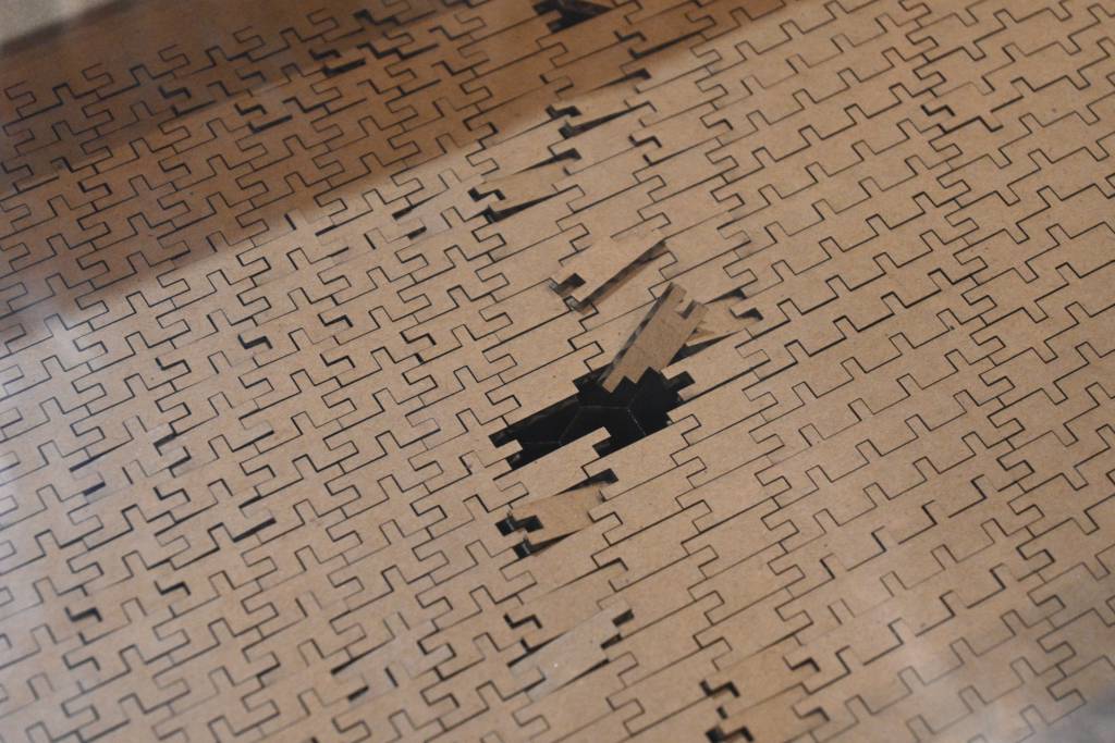
- I was happy to create kit pieces from a whole cardboard with no waste
- Getting the lasercutter to cut past the board need smaller material sheets
- I could use discarded cut boards from other, and re-use them to make my pieces
Outlook
- Better mix of sizes. At my first attempt I did cut too many small pieces. Group them to make it bigger, for better play and assembly. (When user-testing the kit with 11 year-olds, this was the Nr 1 complaint)
- Create a online tool that creates the patterns and outputs SVG.
- Other materials. While cardboard is cheap and fast, it does not survive longer play sessions. Plywood is a obvious
- Add chamfer parameter to design. The no chamfer approach works with cardboard, but plywood or acrylic would need chamfers.
Appendix: Extra Work
ABZ DNA Parametric Construction Kit
Background and Idea
Sketches
Parametric Design in Fusion 360
Learning Outcomes & Observations
Not enough lab time to finish it properly.
Cutting Vinyl Test Patterns for Microfluidic Devices
Characterisation
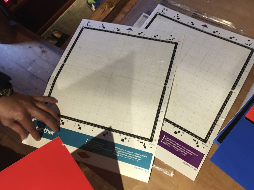
At the FabLab Kamakura, we have a Brother CM550 Vinyl Cutter, as this was my first time using a Vinyl Cutter, I wanted to know it's limitations and possibilities.
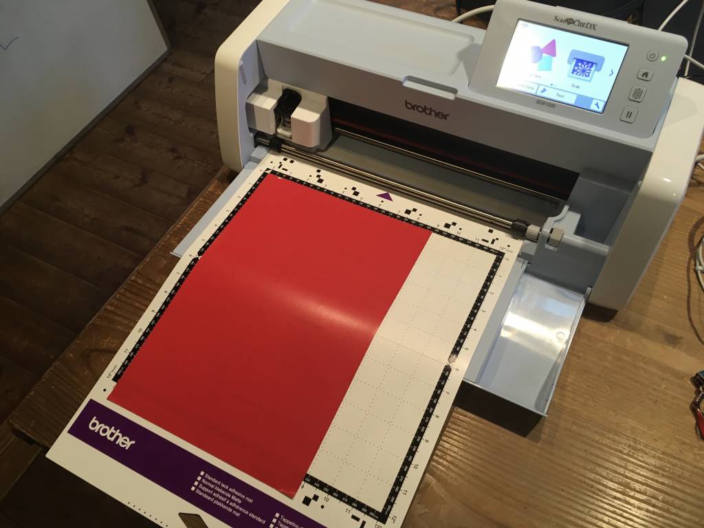
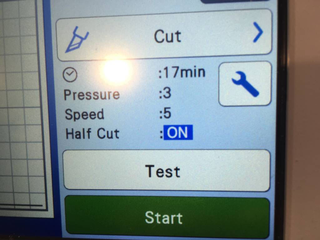
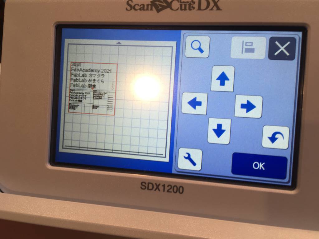
For getting data into the Vinyl Cutter you have two option: Either install the driver software on your computer or transfer the data via a USB Stick to the cutter. I choose the second method. After inserting the stick in the cutter, you can open it using the touchscreen UI and start the print process.
Test Design
I designed a simple graphic with fonts of different sizes and some geometric pattern.
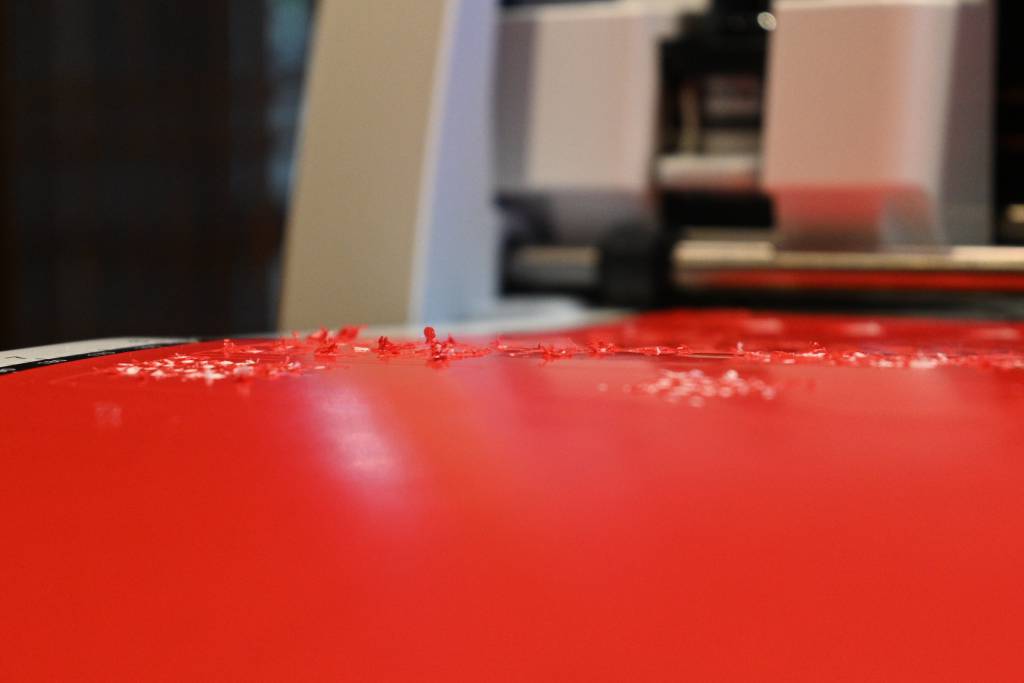
The sheet you want to cut is put on a sticky - or semi-sticky mat - which should counteract the force the blade and cutting movement is applying to the vinyl sheet.
Also, before using a new material, make test cuts with the build-in test pattern, to make sure, the cut goes through the vinyl, but NOT through the mat. (which can tell it's long and eventful history of too deep cuts.)
Being satisfied with the test cuts, we proceed to cut my test sheet.
Test Result
Hmmm.
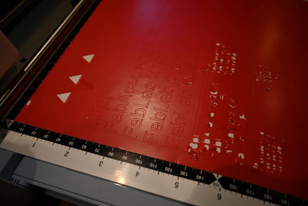
Small font sizes with tight turns (like Kanji characters) are beyond the limit of Vinyl cutters. Straighter lines can be thin.
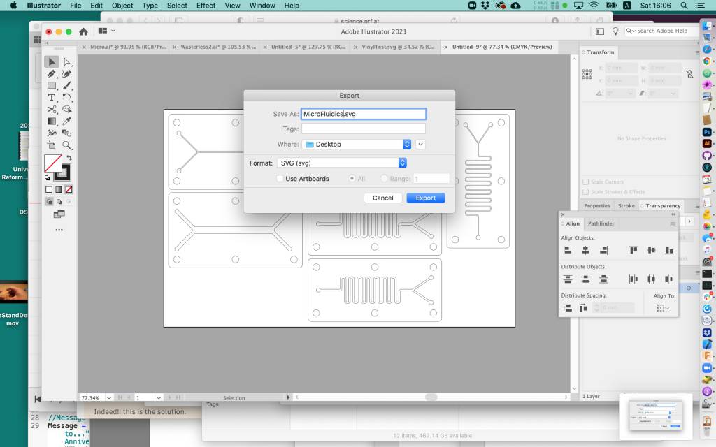
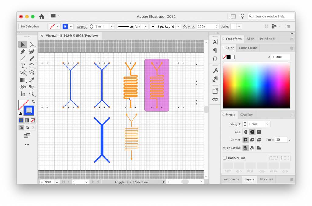
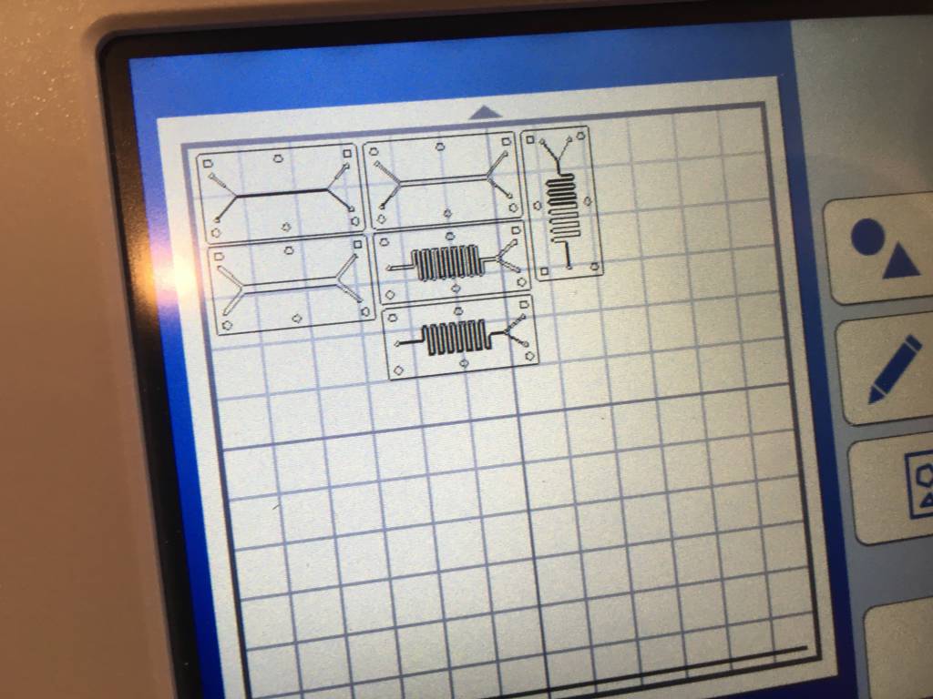
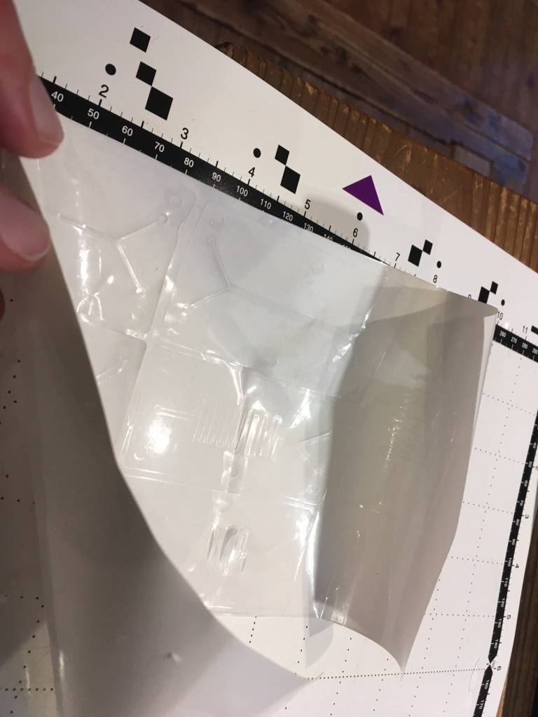
DIY Microfluids Test Pattern
I wanted to try out DIY Microfluids since some time, some simple designs.
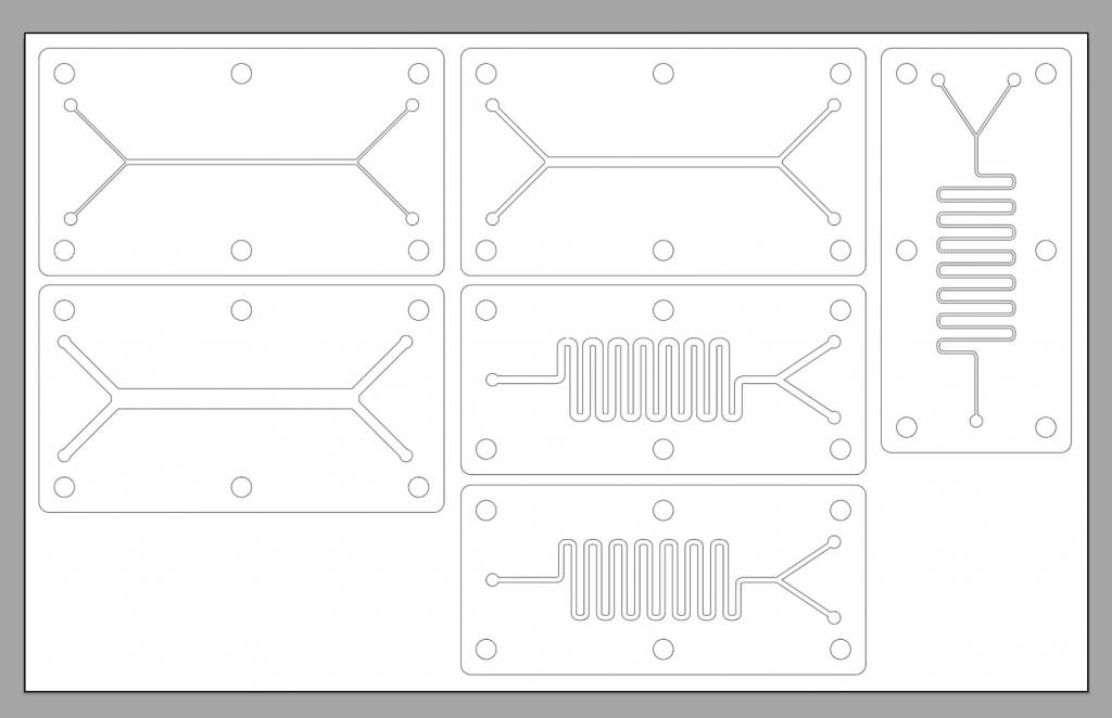
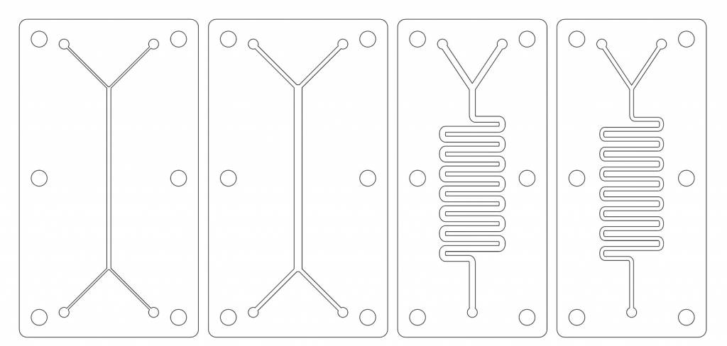
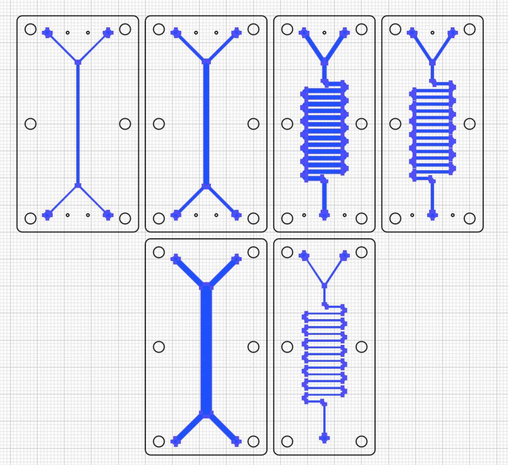
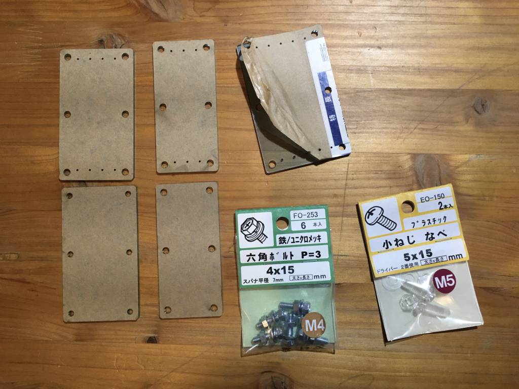
The Vinyl will be sandwiched between 2 transparent acrylic plates, which I cut the the lasercutter, according to the cutting suggestions of the lab. In the plates we have holes for screws, that hold the plates together - and hopefully apply enough pressure to keep the fluids in place. I also cut access ports for the inlets and the outlets into the top plate.
Cutting
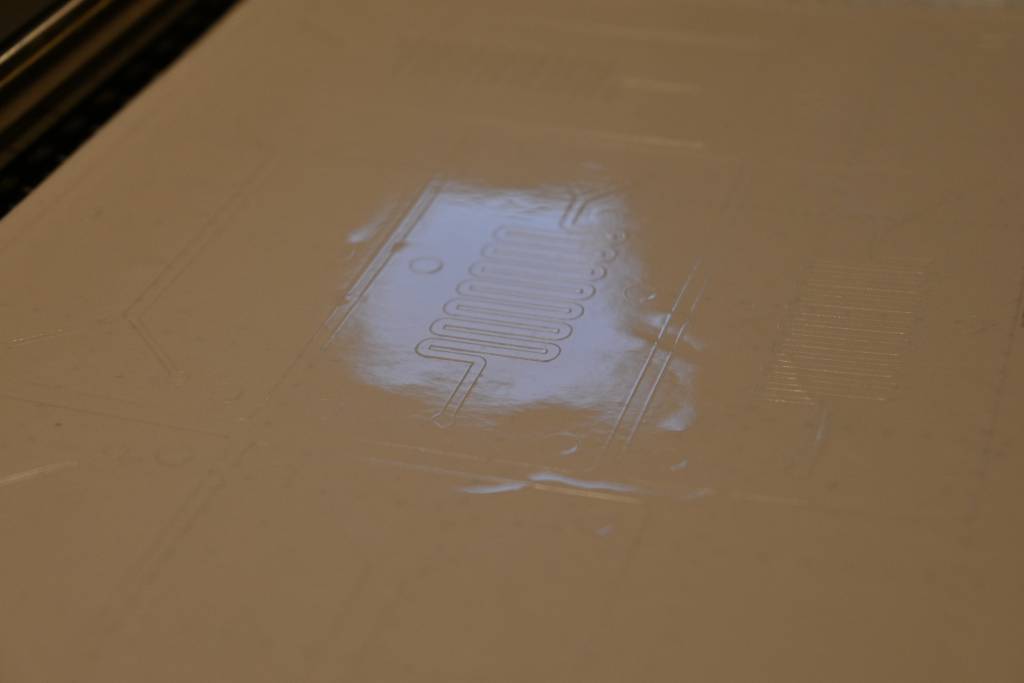
Mistakes
Looking for a transparent sheet to cut in out shared material box, I found one, applied it to the sticky mat, and proceeded with the cutting. Cutting worked well, when I wanted to peel the sheet from the mat, things went wrong. I unintentionally used a transfer sheet for cutting (no markings on the back!), which decided to stick to the cutting mat. Trying to peel it off, I ripped the paper backside.
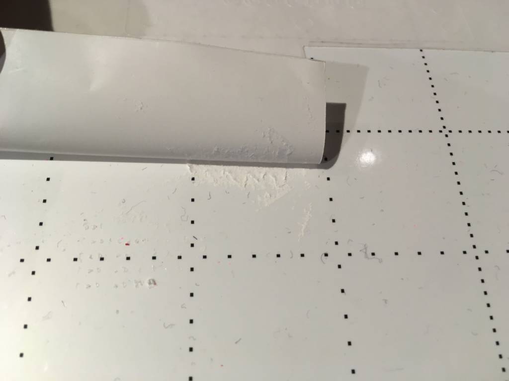
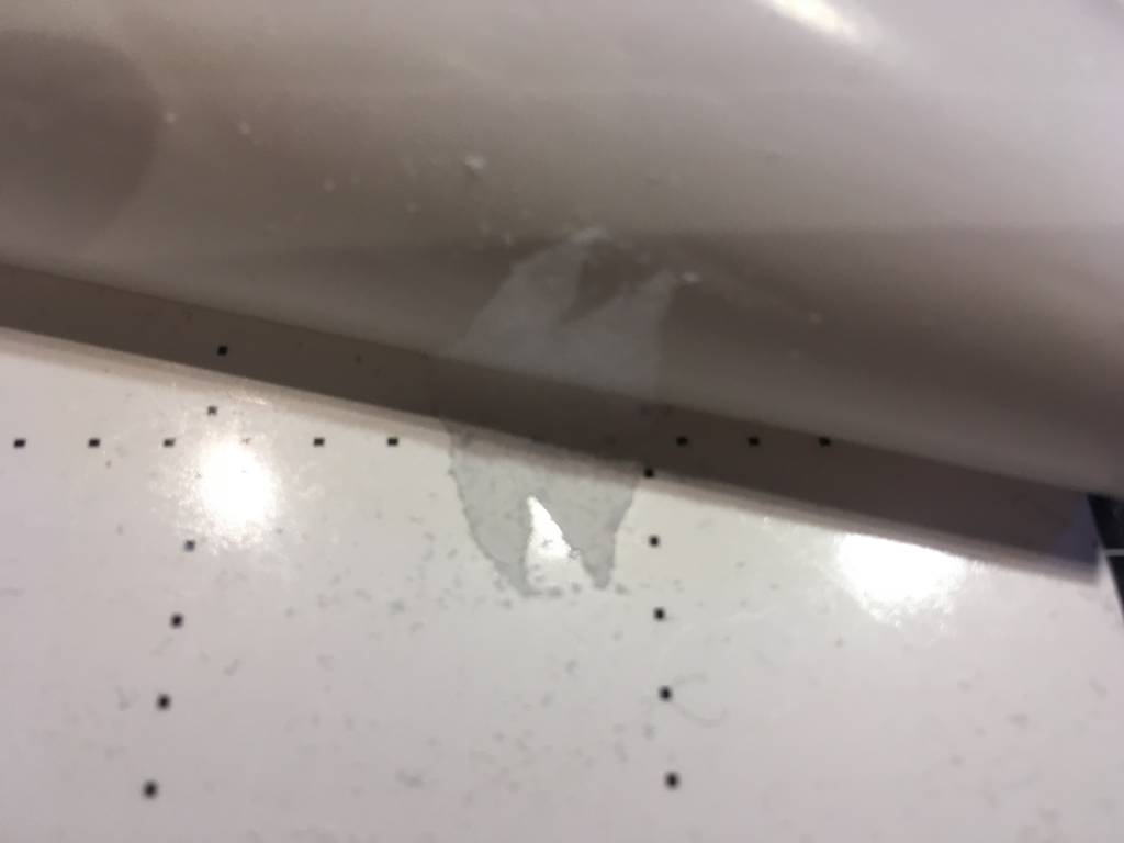
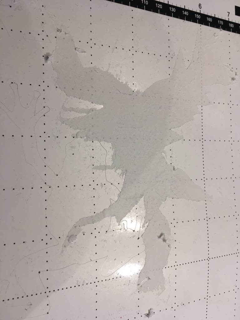
Learning Outcomes & Observations
- The tubing necessary for the in- and outlets did not arrive in time, I still need to test it leakiness.
Notes & References
1 Idea: Collect all PDK from FabAcademy, Classify and Synthesize new PDKs.
2 Why 85% Power and not 100%? Because using 100% Power of the laser-cutter stresses the laser and the machine and would decrease the lifespan of the machine.