8. Electronics Production
Individual assignment:
Make and test the development board that you designed to interact and communicate with an embedded microcontroller
Individual Assignment
-
This assignment is to take the board that I designed in for Electronics Design and manufacture and test it with the knowledge we gained in the Embedded Programming week.
-
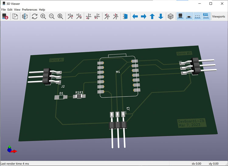
The board I designed was allowed to two servos motors to be connected along with an input. My thought for this week is to use a potentiometer for the input and use that to move the servos at different rates with only one input.
Programming the Board.
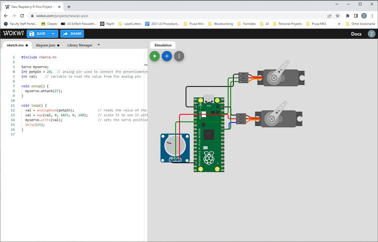
Before I manufacture the board I want to test out the design virtually in Wokwi.com. This site is one that Mr Dubick made us aware of during Embedded Programming, so I decided to put it to good use and test the RP2040 virtually and see if I could get it to run two servos off one potentiometer. In the end I was successful without too much sunk time.
-
I used an example of a servo and potentiometer on an Arduino as my example and reconfigured it for use on a Pico first.
-
After that I put an additional servo in the system to be controlled with the potentiometer. The servos are connected to the same output pin and move in sync. 1.
-
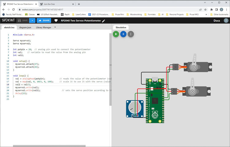
The next iteration is to have the servos controlled with different output pins and move independently. Instead of having a common signal pin for both servos, I used two different pins and scaled the outputs so one output was half the other one. It worked 1.
-
One item to note was that when I was wiring up the potentiometer, it did require an analog pin, so the map function could convert the signal to something the microcontroller could use. It appears that the pin 28 on the Pico has an analog to digital converter function.
Milling the Board
Now that I am comfortable with the coding for my development board, it’s time to mill it. That was fairly straightforward.
-
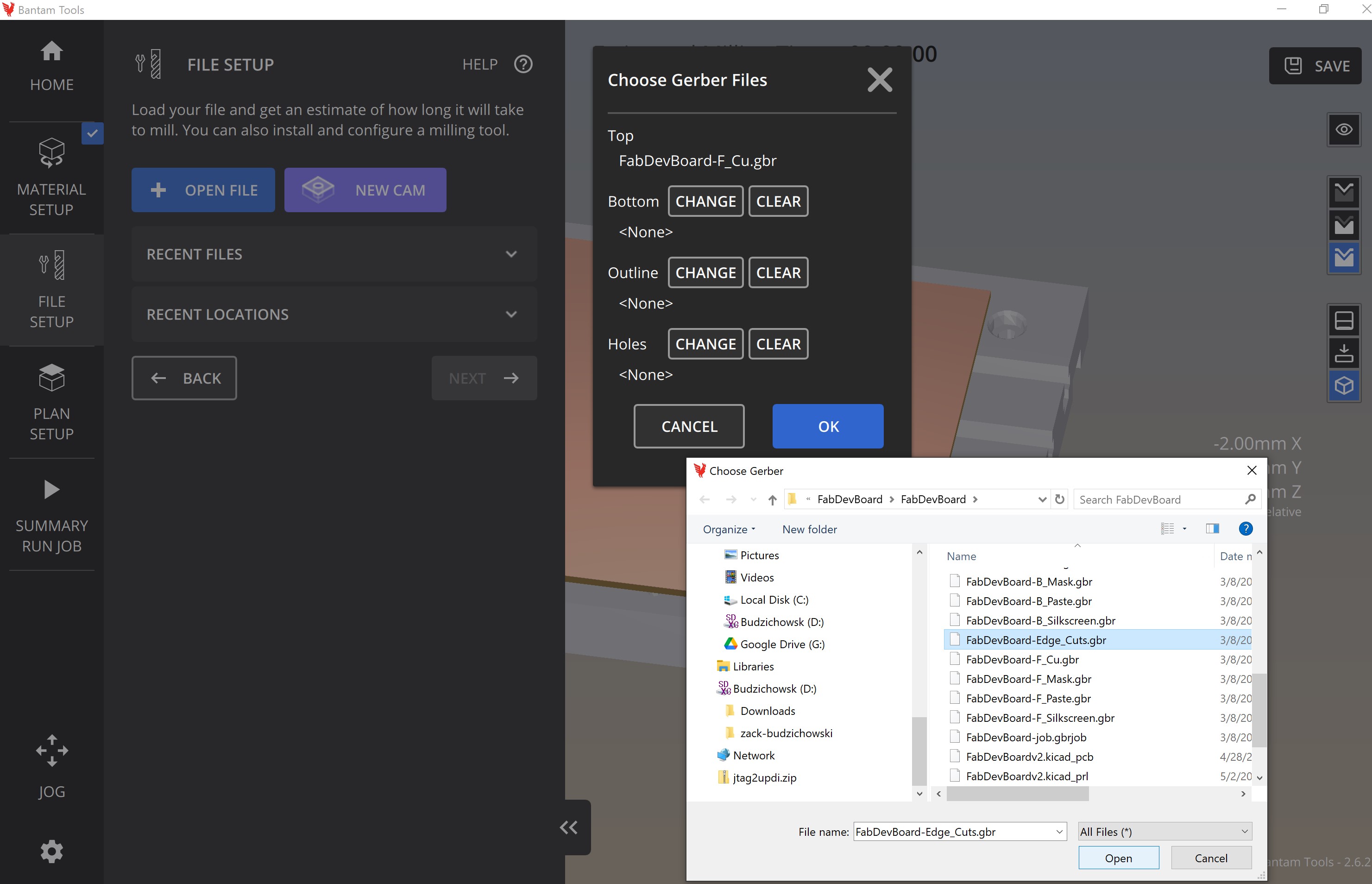
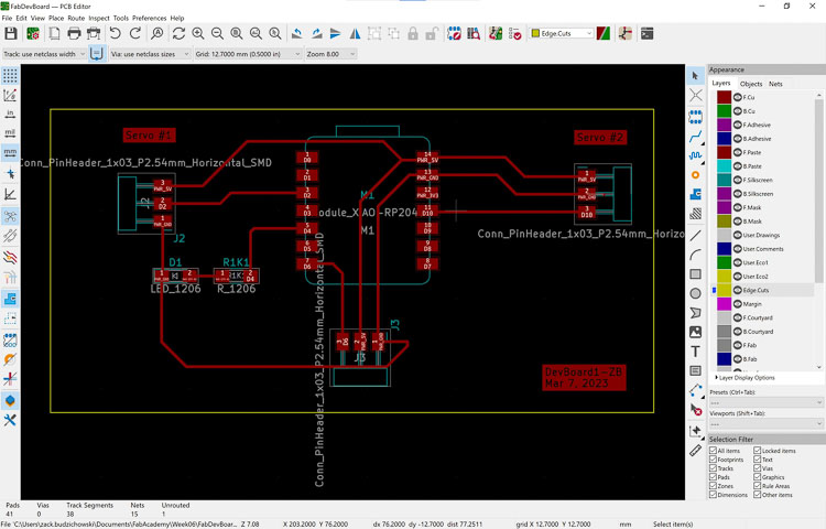
I opened the gerber files from week 6 in the Bantam Tools Milling Machine Software.
- Select Open File and navigate to the location of the Gerber files
- Select the file with “-F Cu.gbr” as its the front copper file
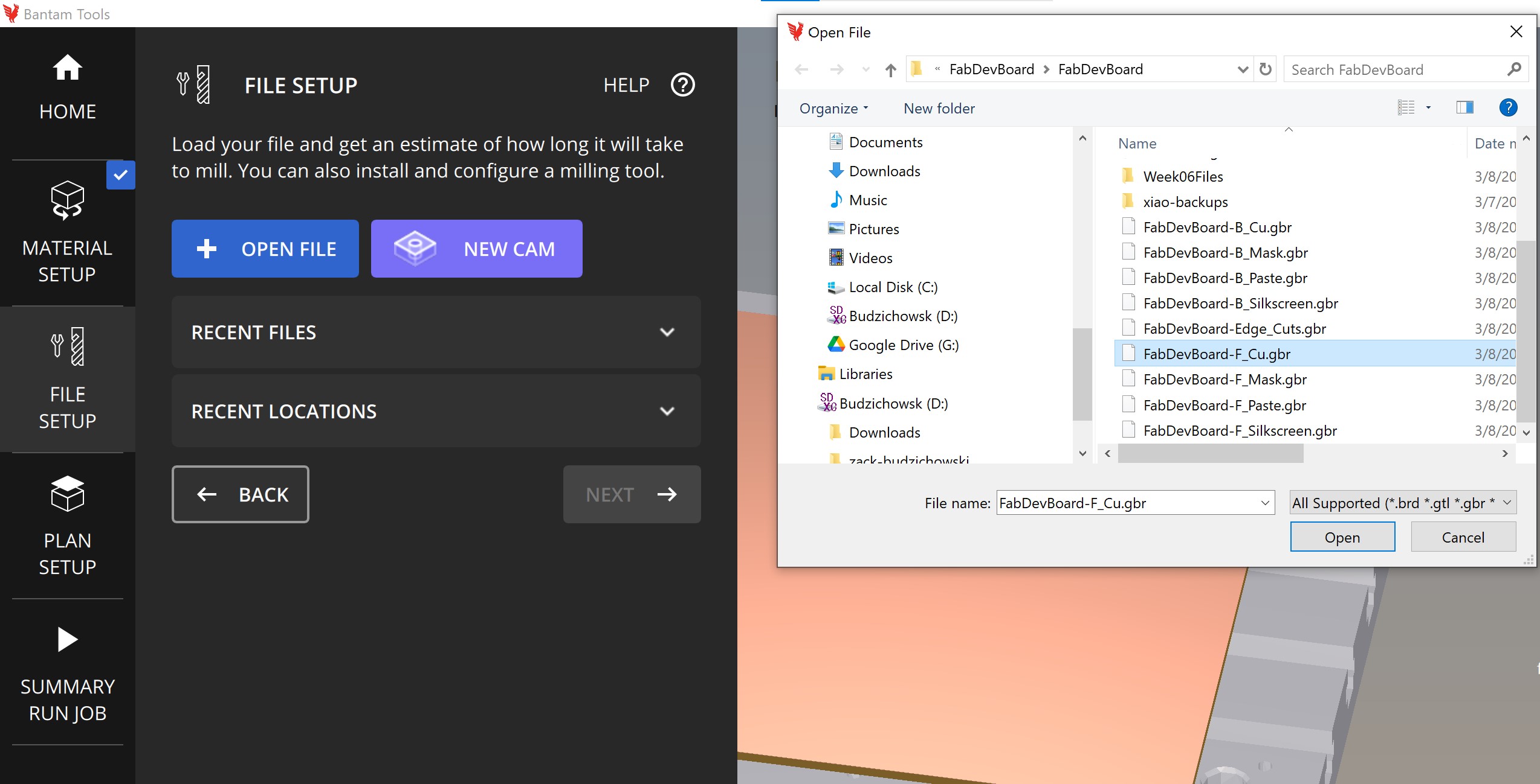
- This dialog box opens where you will add the “Edge Cuts” Gerber file after selecting “Change”
-
And here’s the result

-
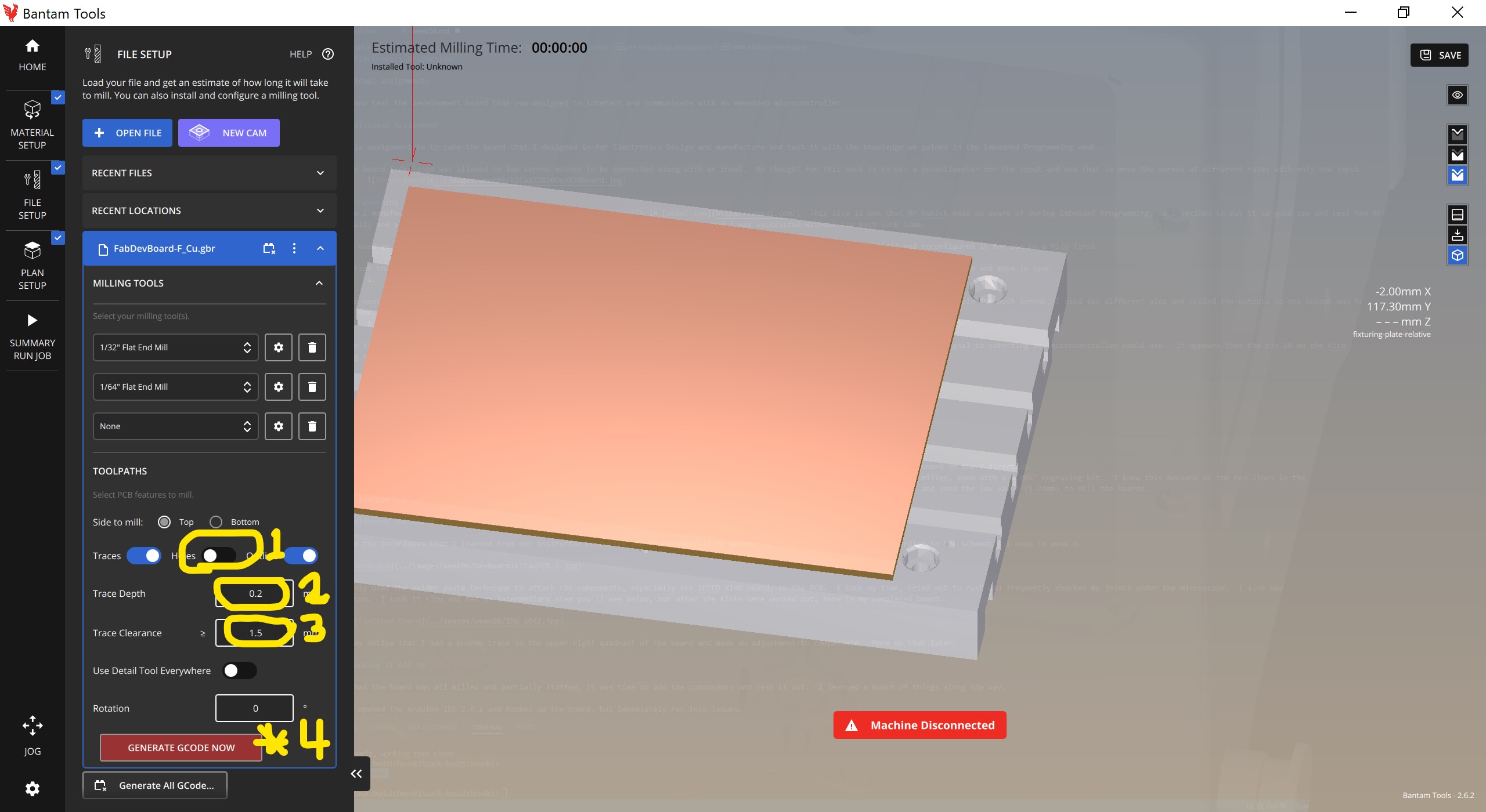
After selecting the 1/32” End Mill along with a 1/64” End Mill, I turned holes off, set the traces to 0.2 mm depth and the trace clearance to 1.5 mm. After that is all done, press the “Generate G-Code Now” button and see the result.
-
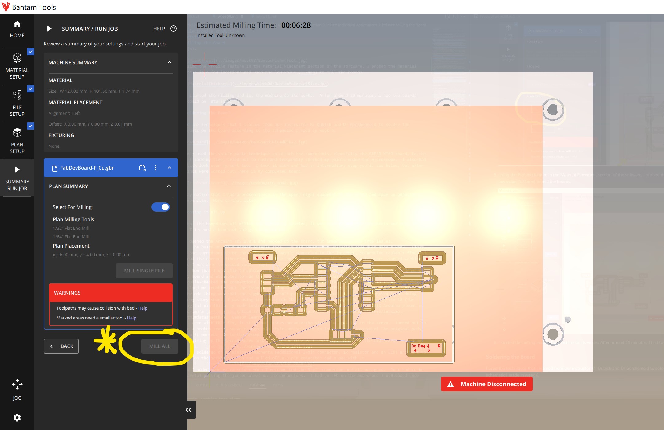
One issue that came up was in my board design I had added some text to name the ports and the board, but it was too small to be milled, even with a 0.005” engraving bit. I knew this because of the red lines in the software output below.
-
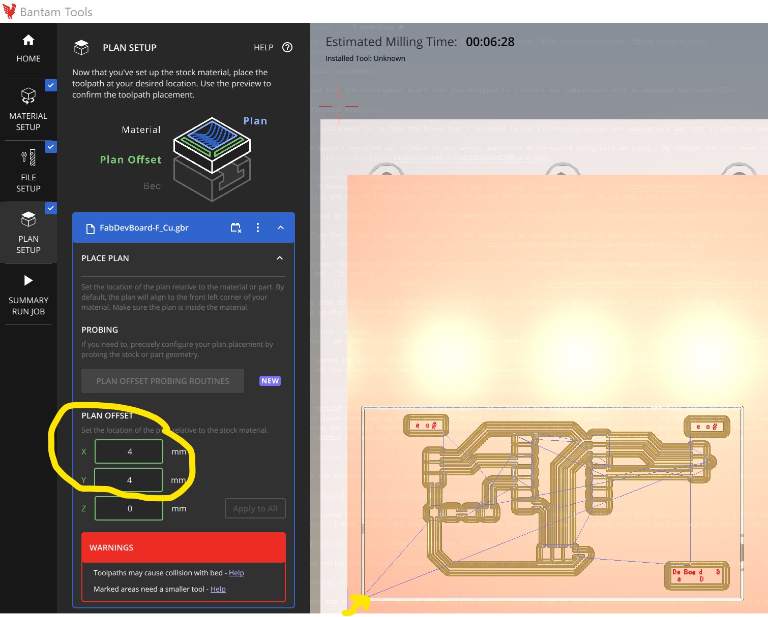
It’s also important to place the plan in the correct place on the PCB board. I generally offset the initial gerber file on a new board to (4,4). The output will update automatically once you’ve entered the value(s).
 5. Using the Probing feature in the Material Placement section of the software, I probed the material thickness in a few locations and used the low value (1.74mm) to mill the boards.
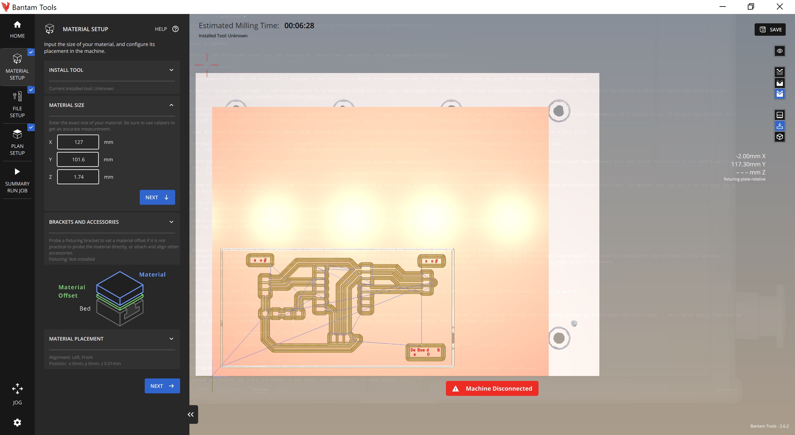
-
After you have set all the above up select “Summary Run Job” on the left side of the screen and the option below will pop up. When connected to the machine, you will be able to start the job.
I started the milling and let the machine do its works. After around 20 minutes, I had two boards that could be ‘stuffed’.
Soldering the Board
I used the techniques that I learned from our instructor Mr Dubick and Dr Gershenfeld to solder the components on the board according to the schematic I made in week 6.
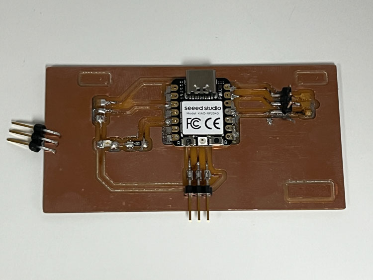
I mainly used the solder paste technique to attach the components, especially the SEEED XIAO board, to the PCB. I took my time, tried not to rush and frequently checked my joints under the microscope. I also had Mr Dubick look over my work too. I took it slow and had an intermediary step you’ll see below, but after the kinks were worked out, here is my completed board.
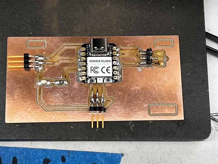
You may notice that I had a broken trace in the upper right quadrant of the board and made an adjustment to compensate. More on that later.
Hooking it All Up
Now that the board was all milled and partially stuffed, it was time to add the components and test it out. I learned a bunch of things along the way.
- I opened the Arduino IDE 2.0.1 and hooked up the board, but immediately ran into issues.
- The board wouldn’t accept example code. It had power, but uploading code just didn’t work. First issue turned out to be that my computer wasn’t connected to the Internet, so Arduino couldn’t find and load the correct libraries. I solved that by reconnecting my Wi-Fi and the Internet started working, so I was able to upload code. Yay!
- Now that I was able to upload code, I connected a servo to the pins on the upper right quadrant of my board and attempted to run the example ‘Sweep’ code from Arduino. It didn’t work. I double-checked the connections (power, ground and digital pin 10) and it all seemed fine. Mr Dubick helped me troubleshoot the issue and using a multimeter we verified the power, ground and signal pin. The odd thing was that the signal pin wasn’t putting out a signal like it was supposed to be doing. Long story short, I was using the wrong pin ID. I thought I was supposed to be using pin 10 (for digital pin 10) in my code instead of the pin 3 that it was mapped to based on GPIO Arduino pinout on Adrian’s infomration. Lesson learned.
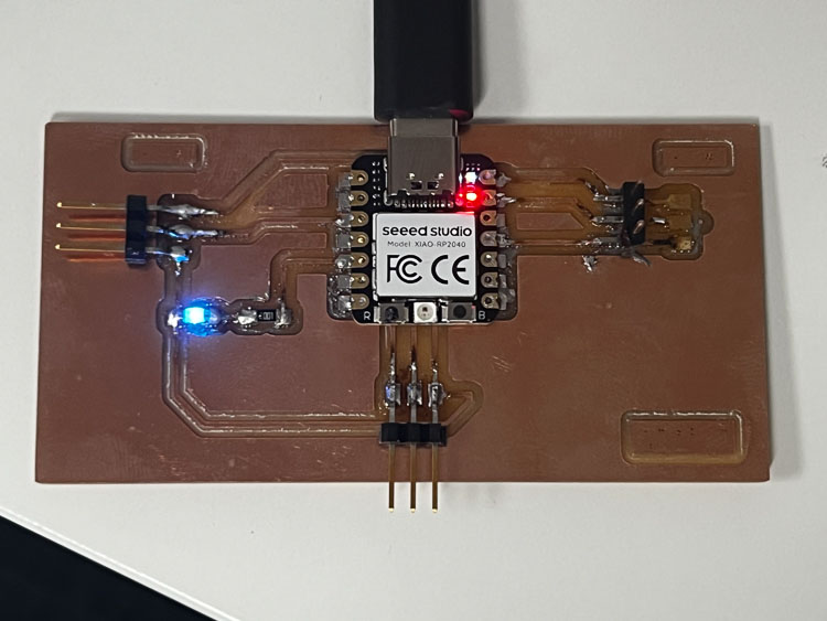
- Even with that fix, it still had issues because the signal was getting to the servo. Turned out to be a broken trace, so we changed pin style and soldered on to the trace instead of the original pads. Now it worked. On to the second servo.
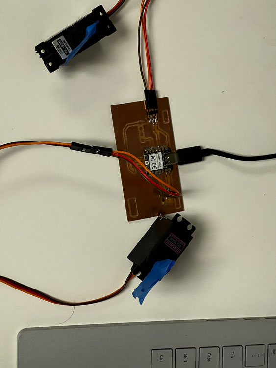
- Wiring up the second servo and loading the code went smoothly. Here are the two servos hooked up.
- I soldered on remaining components (additional 3-pin connector, 1k resistor and an LED) and went to put on the servos back on and pulled off a 3 pin connector and a pad with it.
- I added some extra solder when I reconnected the 3 pin connector and all was good. Just had to be careful putting the jumper wires on the connectors. I had an LED on the board and I up0loaded code for it only to realize that was in backwards, so I fixed that along with the connector. Then it worked.
- The next I learned was that pin 0 was a digital pin and not an analog one. My code didn’t work. The servos would go to the initial position, but wouldn’t move with the potentiometer. After some thinking, I realized I had to rearrange a servo and the potentiometer, so it was connected to an analog pin(28). I rearranged the items and adjusted the code, and it all worked!!!
- I still need to figure out how to embed video, so that is my next task.
Link to my files for the week.
Group Assignment
Link to our group assignment.