9. Output Devices
This week’s assignment is to add an output device to a microcontroller board you’ve designed and program it to do something.
I’m going to take the board I designed and milled last week and add a stepper motor to it using a h-bridge motor driver. I’ll have to have some dual use pins from the three pin connectors I had on the board, but I think I can make it work. If it does, then I will redesign the board for future use during machine week.
Motor Control
-
I spent time researching the various ways to control a motor using a microcontroller and an H-bridge.
- I reviewed the H-bridge website that Rico mentioned in the Saturday open time to get a better understanding of the theory.
- I also reviewed Neil’s lecture from March 22nd around the 44:45 mark to see if I could garner a better understanding on how to take the theory and put it into practice. That helped to understand the basics of how to drive the motor. One item that Neil noted was Adrian Torres’s motor driver for his FabXIAO board and showed a brief video of it. I searched for the design and couldn’t locate it. My best guess from the screenshot was that it was based off of the design of Neil’s A4953 board. I did find Adrian’s Adrianino board site and the DC motor section that used
- I did note the A4953 chip that Neil used in his design and located an A4950 in our lab and spent time researching the differences between the chips by comparing the datasheet for each and deciding the A4950E will operate similar to the A4953. They share the same pinout for the 8 pin versions, so the code should be interchangeable between the two.
-
I have questions about the correct way to design a board using the A4950 and it’s BOM, so I will take a break and turn my attention to using a premade motor driver.
- The L298N is a DC motor driver that we have in our lab, so I decided to see if I could get it to work with my development board from last week.
- I found a good tutorial on the L298N driver on Last Minute Enginees here
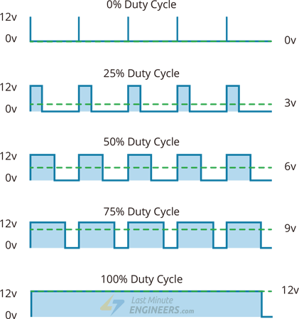
- The tutorial helped me better understand the concept and theory behind Pulse Width Modulation (PWM) for motor control. Essentially, duty cycle is the average voltage applied to a DC motor based on the width of the on/off pulse applied to the motor. See image below from LastMinuteEngineers.com
- First attempt to hook up and run code to control a DC motor on my development board. I’m using the code from LastMinuteEngineers.com to test my setup.
// L298N DC Motor Driver Code
// Base code is from
// https://lastminuteengineers.com/l298n-dc-stepper-driver-arduino-tutorial/?utm_content=vc-true
// Adapted for FabAcademy 2023 Output Devices by Zack Budzichowski March 28, 2023
// Pins are set for a seed studio XIAO RP-2040 and electronics production development board from March 21, 2023
// Motor A connections
int enA = 28;
int in1 = 3;
int in2 = 0;

void setup() {
    // Set all the motor control pins to outputs
    pinMode(enA, OUTPUT);
    pinMode(in1, OUTPUT);
    pinMode(in2, OUTPUT);

    // Turn off motors - Initial state
    digitalWrite(in1, LOW);
    digitalWrite(in2, LOW);

}

void loop() {
    directionControl();
    delay(1000);
  speedControl();
    delay(1000);
}

// This function lets you control spinning direction of motors
void directionControl() {
    // Set motors to maximum speed
    // For PWM maximum possible values are 0 to 255
    analogWrite(enA, 255);

    // Turn on motor A & B
    digitalWrite(in1, HIGH);
    digitalWrite(in2, LOW);
    delay(2000);

    // Now change motor directions
    digitalWrite(in1, LOW);
    digitalWrite(in2, HIGH);
    delay(2000);

    // Turn off motors
    digitalWrite(in1, LOW);
    digitalWrite(in2, LOW);

}

// This function lets you control speed of the motors
void speedControl() {
    // Turn on motors
    digitalWrite(in1, LOW);
    digitalWrite(in2, HIGH);

    // Accelerate from zero to maximum speed
    for (int i = 0; i < 256; i++) {
        analogWrite(enA, i);
            delay(20);
    }

    // Decelerate from maximum speed to zero
    for (int i = 255; i >= 0; --i) {
        analogWrite(enA, i);
            delay(20);
    }

    // Now turn off motors
    digitalWrite(in1, LOW);
    digitalWrite(in2, LOW);

}
-
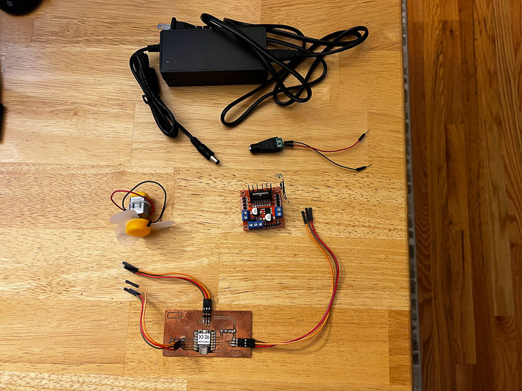
Here are the parts for my setup
-
Here is everything put together
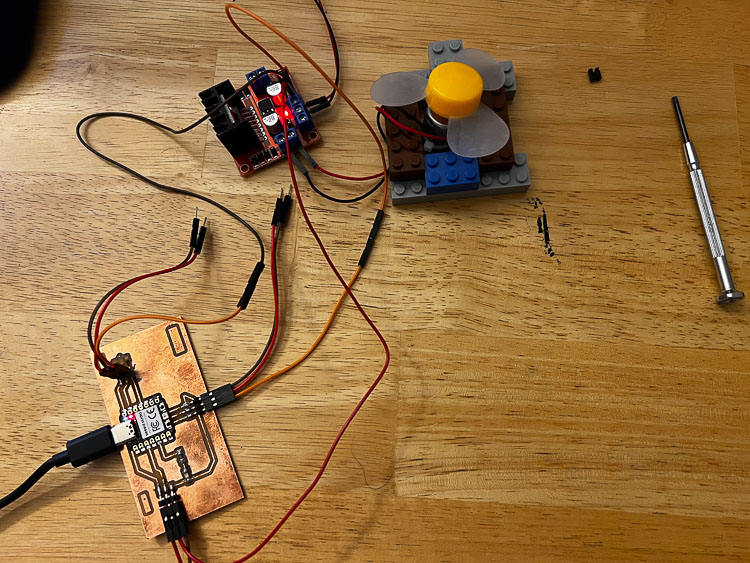
- The tricky part was that I had to use the three data pins from my development board to rum the motor control unit. The two input pins were pin 0 and pin 3 on the XIAO along with the analog pin 28 for the enA for the pulse width modulation.
-
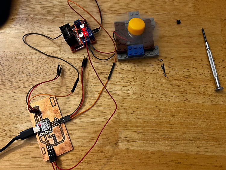
Here is a picture with the motor spinning.
-
Here’s a video of the motor spinning
Link to my design files for the week(same files from Electronics Design Week). Source code is shown above.
Group Assignment
Link to our group assignment.
GitLab Issue-Pipeline Failure
-
When I uploaded my site for the week at the end of the day, I received a “Pipeline Failure” message that needed to be dealt with immediately.
-
My first attempt at repair was to rerun my update and see what happened. In VS Studio Code it seemed to go through and there were no issues, but I quickly received a “Pipeline Failure” email for Academy IT, so I had to try a new strategy.
-
I hadn’t had this issue yet, so I did some quick research on the issue and most the results dealt with merge request problems, so those weren’t helpful as it was for my individual site and I didn’t have any merge requests.
-
At this point I started a methodical analysis of what was happening.
- Closed out my VS Studio Code Workspace
- Signed in to Gitlab to view the status of my files in the repository and they looked fine.
- I rebooted my computer and reopened VS Studio Code and reran the update, it worked. Not sure why, but it did.
- The solution followed one of the first rules of computer troubleshooting: restarting and rebooting solve a high percentage of issues for unknown reasons.