7. Computer Controlled Machining
This week’s task is to make (design+mill+assemble) something big (~meter-scale) extra credit: don’t use fasteners or glue extra credit: include curved surfaces
Individual Assignment
-
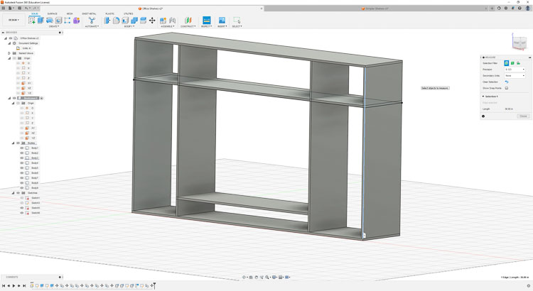
When I started this assignment I thought that I would design and produce some shelving for my desk. It’s in need of some organization. I had visions of a grand hutch to go on my standing desk that would have space for my 34” external monitor and some books. I started designing in Fusion 360.
-
The basics of the design are below.
-
I had planned to tweak it a bit to make it more useful, but thought I would make sure I could turn it into a useable CNC file before I got too far. With the copying and pasting that I did to create the design, I had a difficult time figuring out how to make the tabs and pockets on a sketch layer so that I could export the files as DXF that I could load in to Aspire for the ShopBot CNC.
-
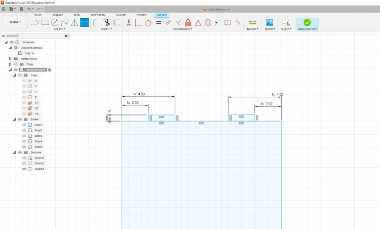
To better understand the process of making a parametric model with press fit joints I designed the sides of a simple bookshelf that was fully parametric.
- I started off with a simple rectangle and added parametric tabs.
- I kept designing and came up with the complete side with lots of parametric options.
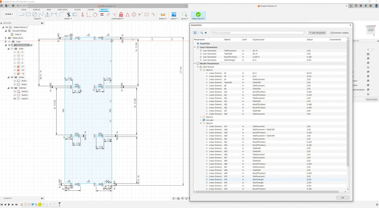
- Here are the parameters that I was able to control (Tab Placement, Tab Width, Wood Thickness and Shelf Height).
- I started off with a simple rectangle and added parametric tabs.
-
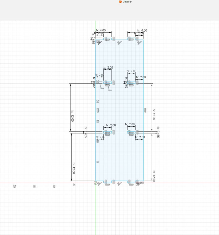
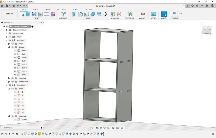
Here is the final design of the simplified bookshelves
-
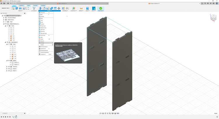
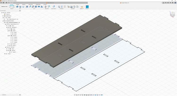
With the sides designed I turned my attention to how to convert the two sides into a DXF file that I could load into Aspire and ultimately the ShopBot CNC. First I tried a simple “Export DXF” option and that didn’t work as intended, so I kept trying. I Googled “Fusion 360 3D Model to Lay Flat for CNC” and found a useful tutorial.
Lay Parts Flat in Fusion 360 with Arrange Feature
-
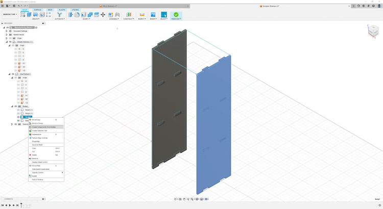
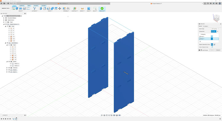
In order to lay parts flat in Fusion 360 the parts must be components, so I needed to convert the shelves that were ‘bodies’ into components. That was an easy step since I just needed to right-click on the body and select ‘Create Component from Bodies’ option and it will create the correct file that can be utilized with ‘Arrange’ feature.
-
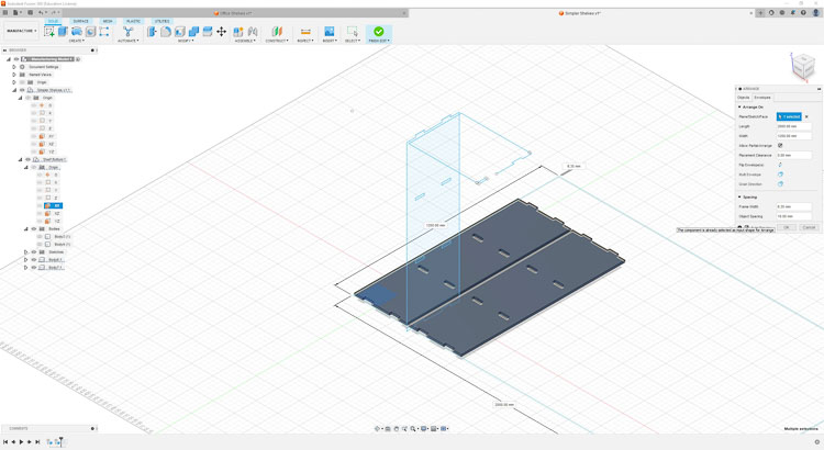
Now that I had the parts flat, I tried to export a DXF and import it into Aspire, and it wasn’t quite right.
-
Consequently, I did some additional research and found a tutorial on how to make a projected sketch on the XY plane from a solid body that could be used to create the CNC file. Prepare a Fusion 360 file for Laser Cutting
-
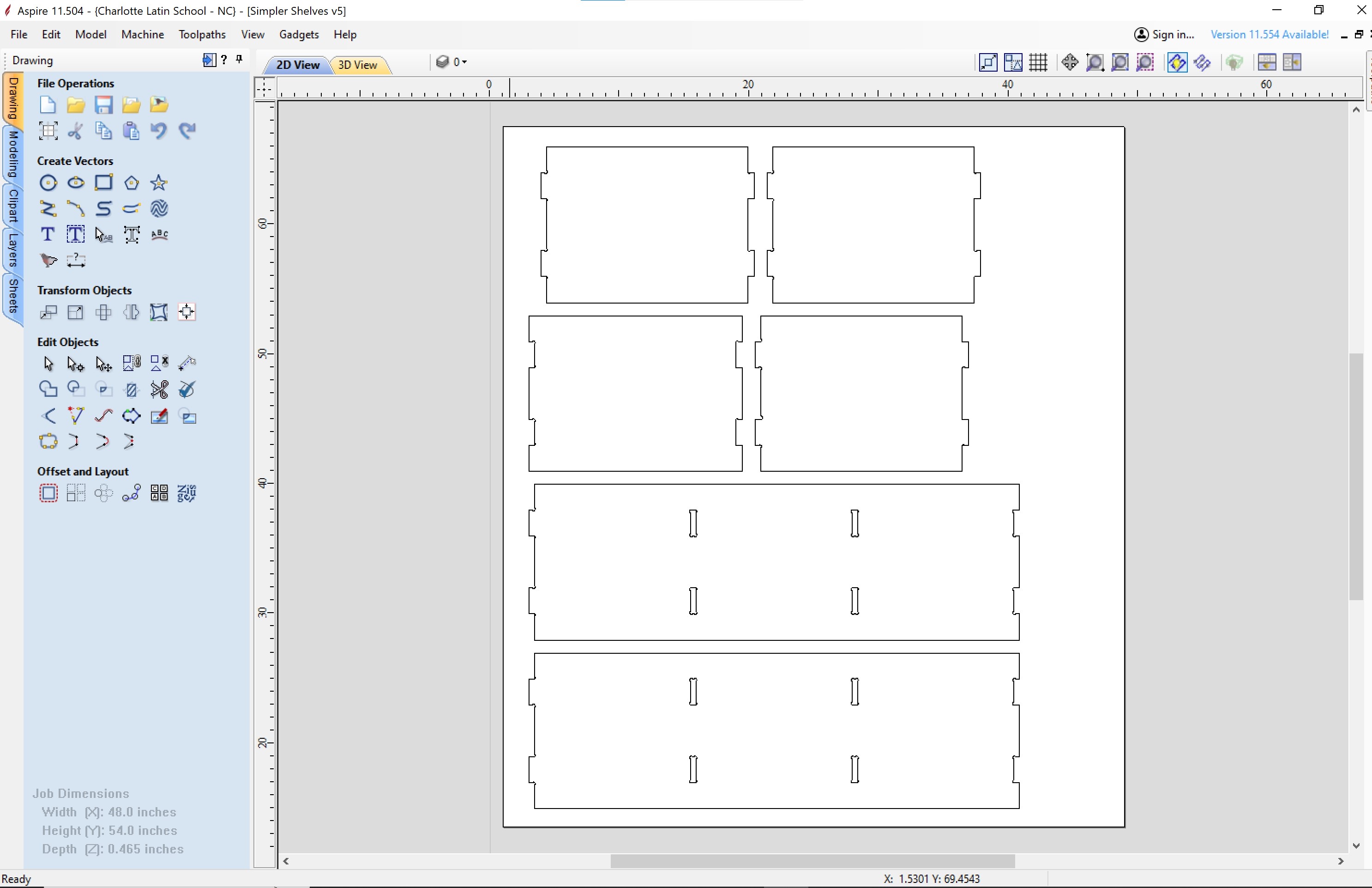
Now that I knew how to create the correct DXF, here is what it looked like.
-
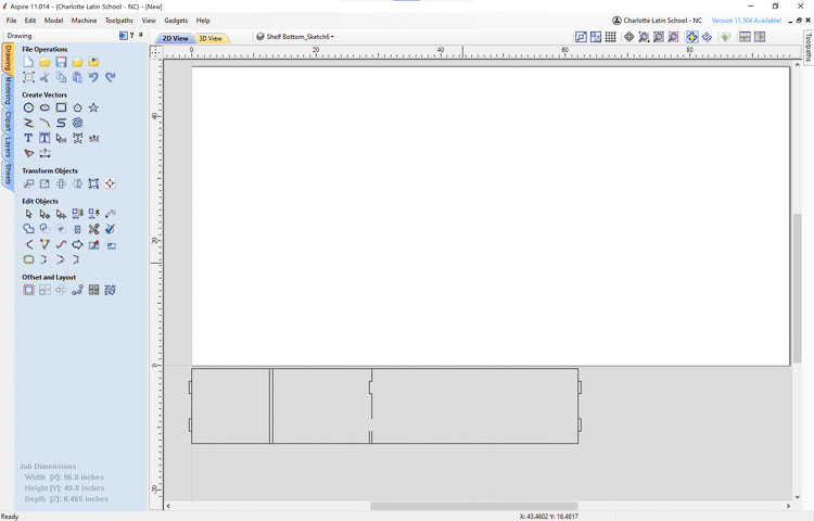
I loaded the projected DXF file in to Aspire and was pleased with the results.
-
Now I need to add shelves to my design along with the dogbones for the press fit shelves using the Lay Flat feature in Fusion 360.
- Now importing the DXF to Aspire results in-
-
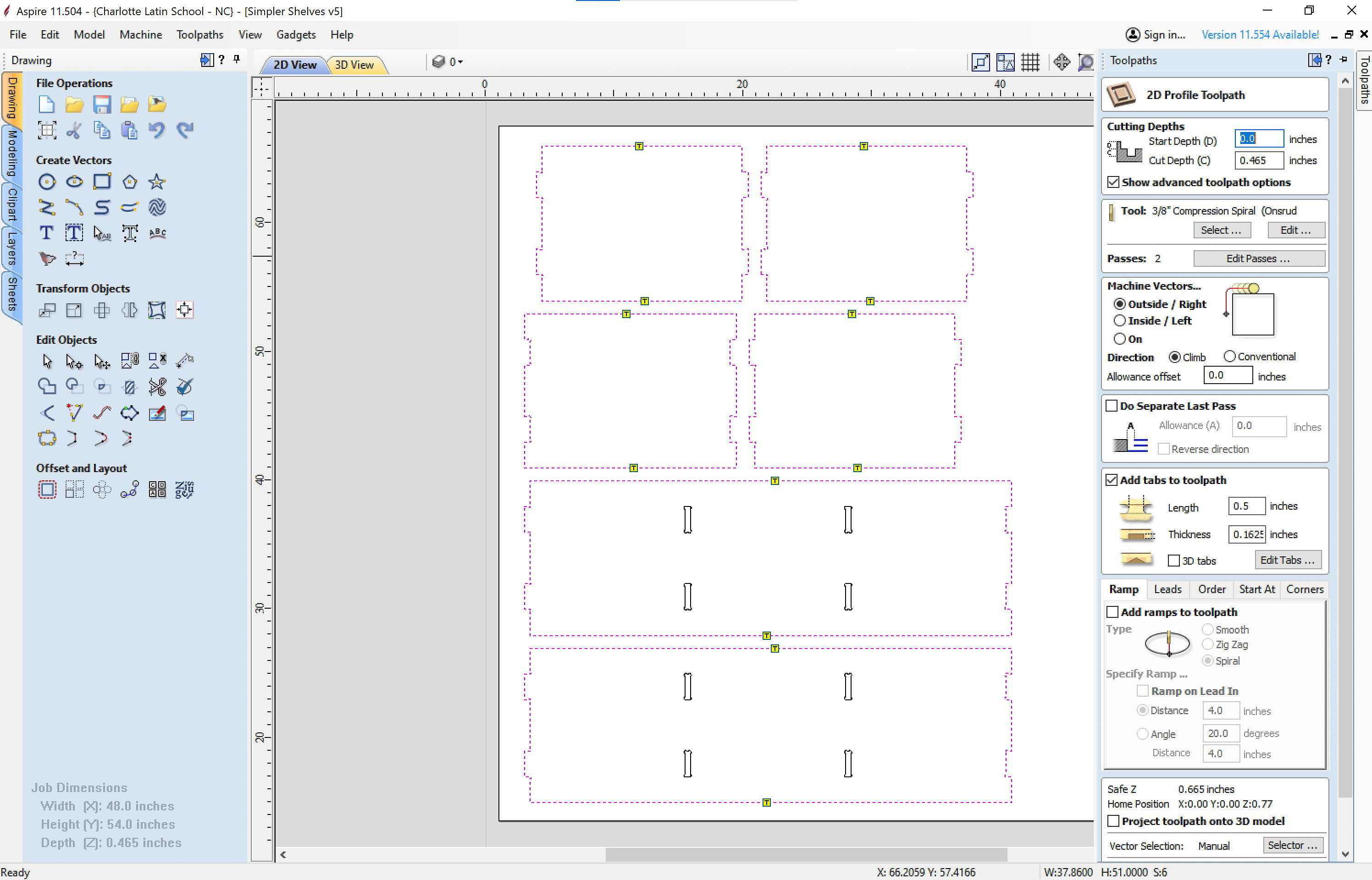
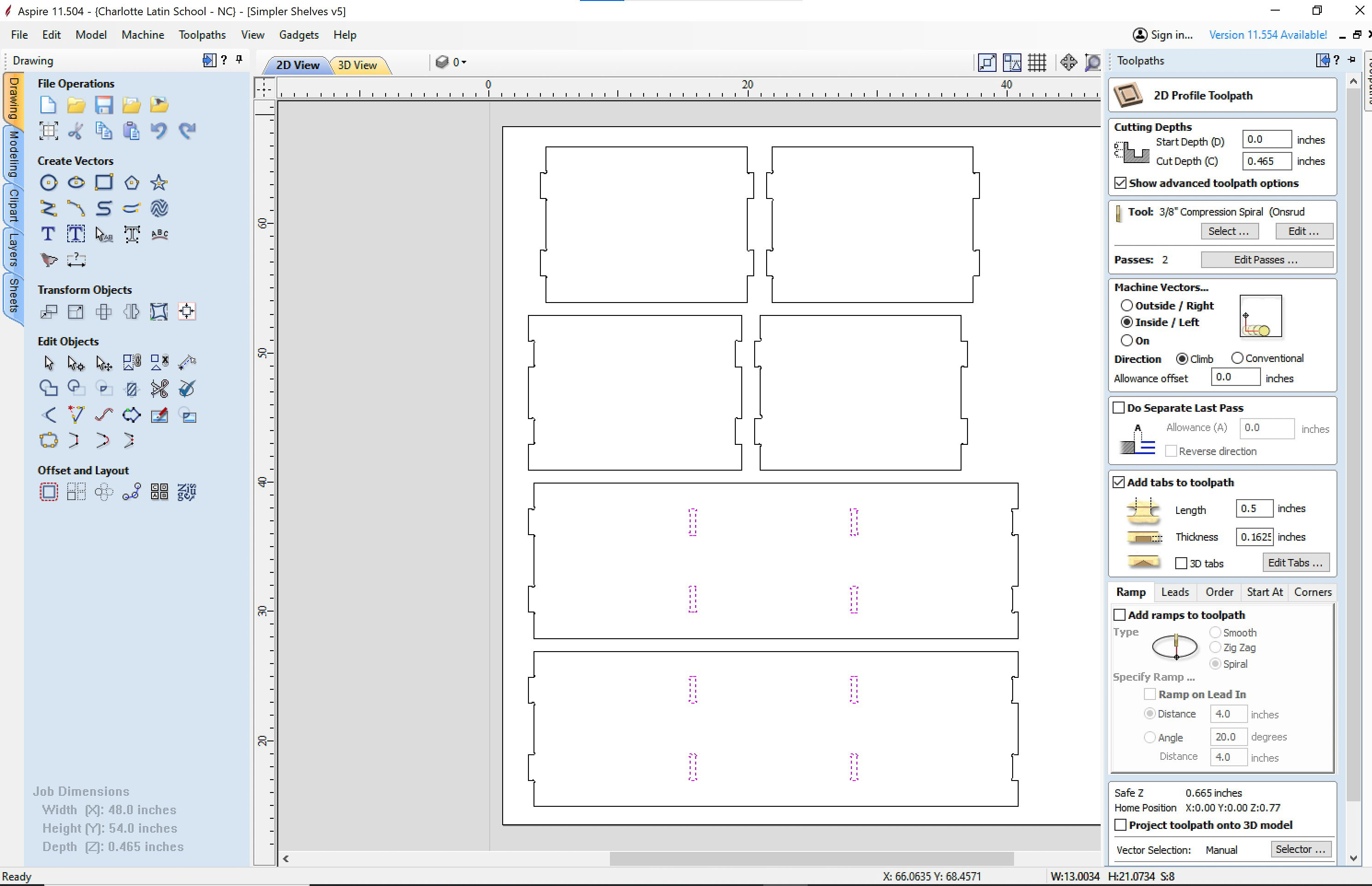
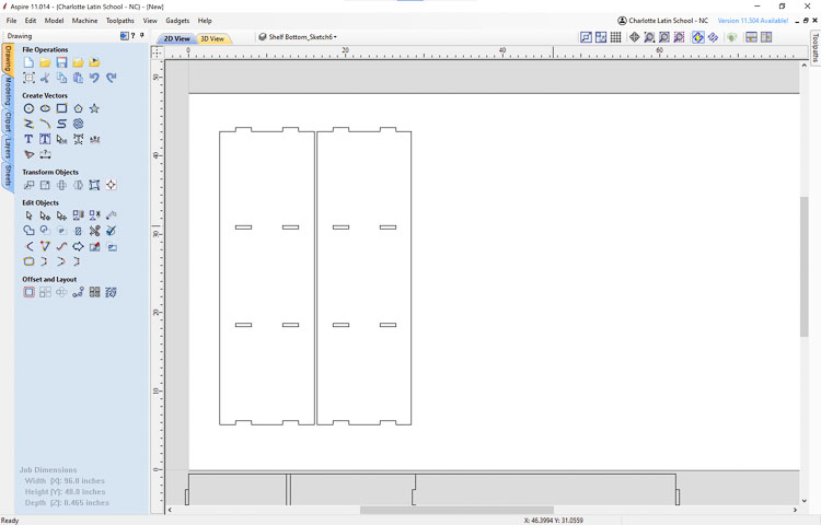
I have everything properly arranged in Aspire, so it was time to make the two required toolpaths (Inside and Outside).
- Outside toolpath with tabs.
- Inside toolpath for dogbones.

Cutting the Shelves
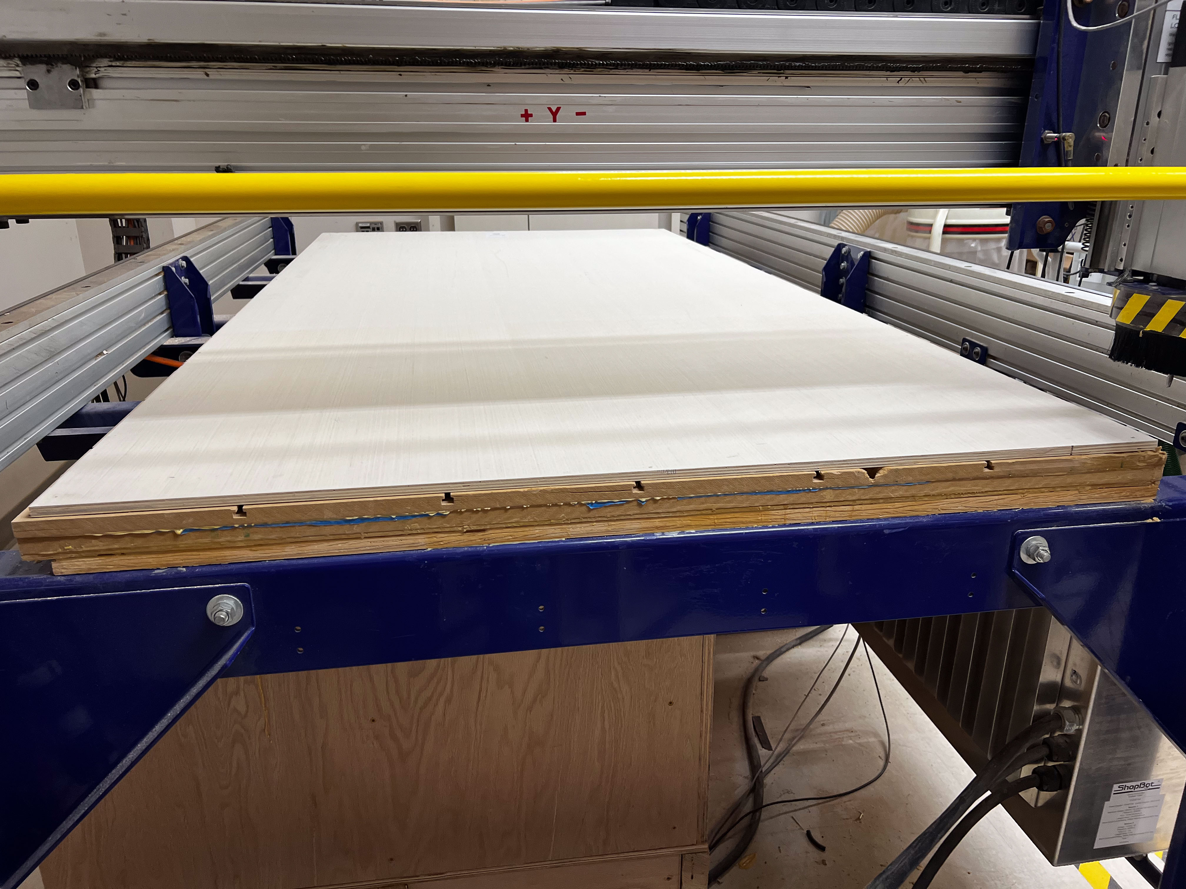
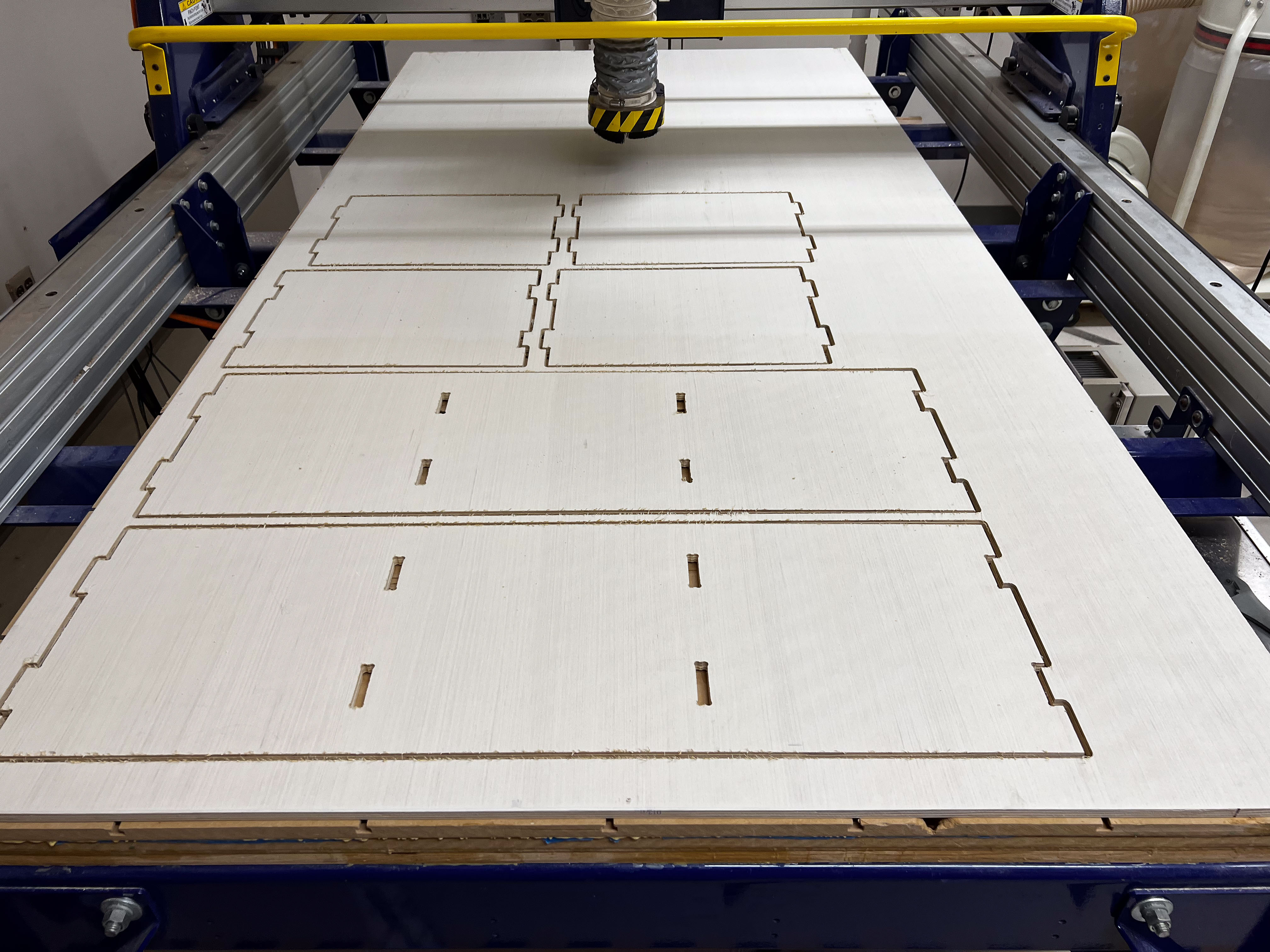
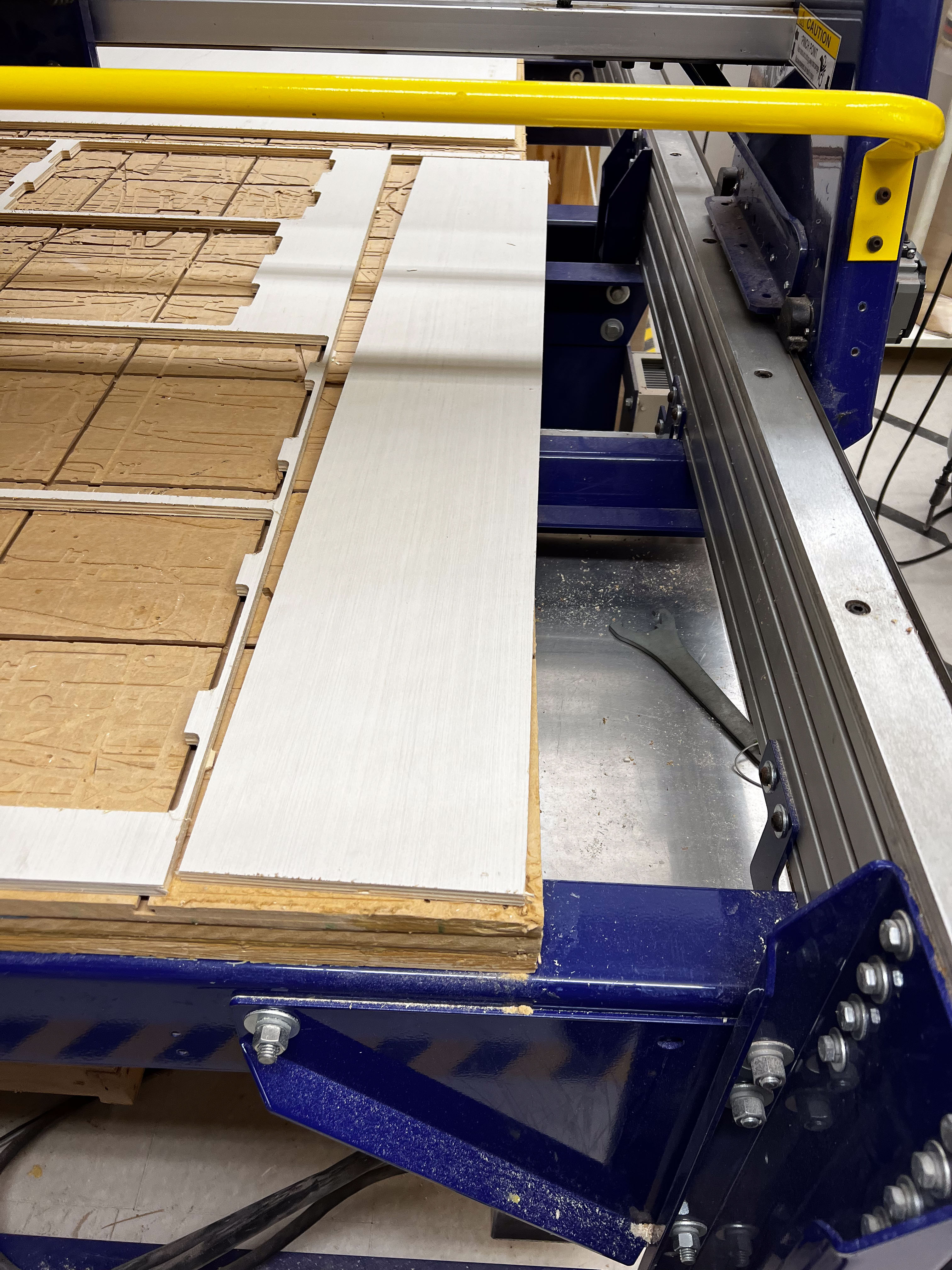
- After exporting the toolpaths from Aspire, I followed the Charlotte Latin FabLab Alpha ShopBot Workflow March 24 2023 when using the ShopBot.
- Here are some photos of the setup and cutting process on the ShopBot.
Assembly
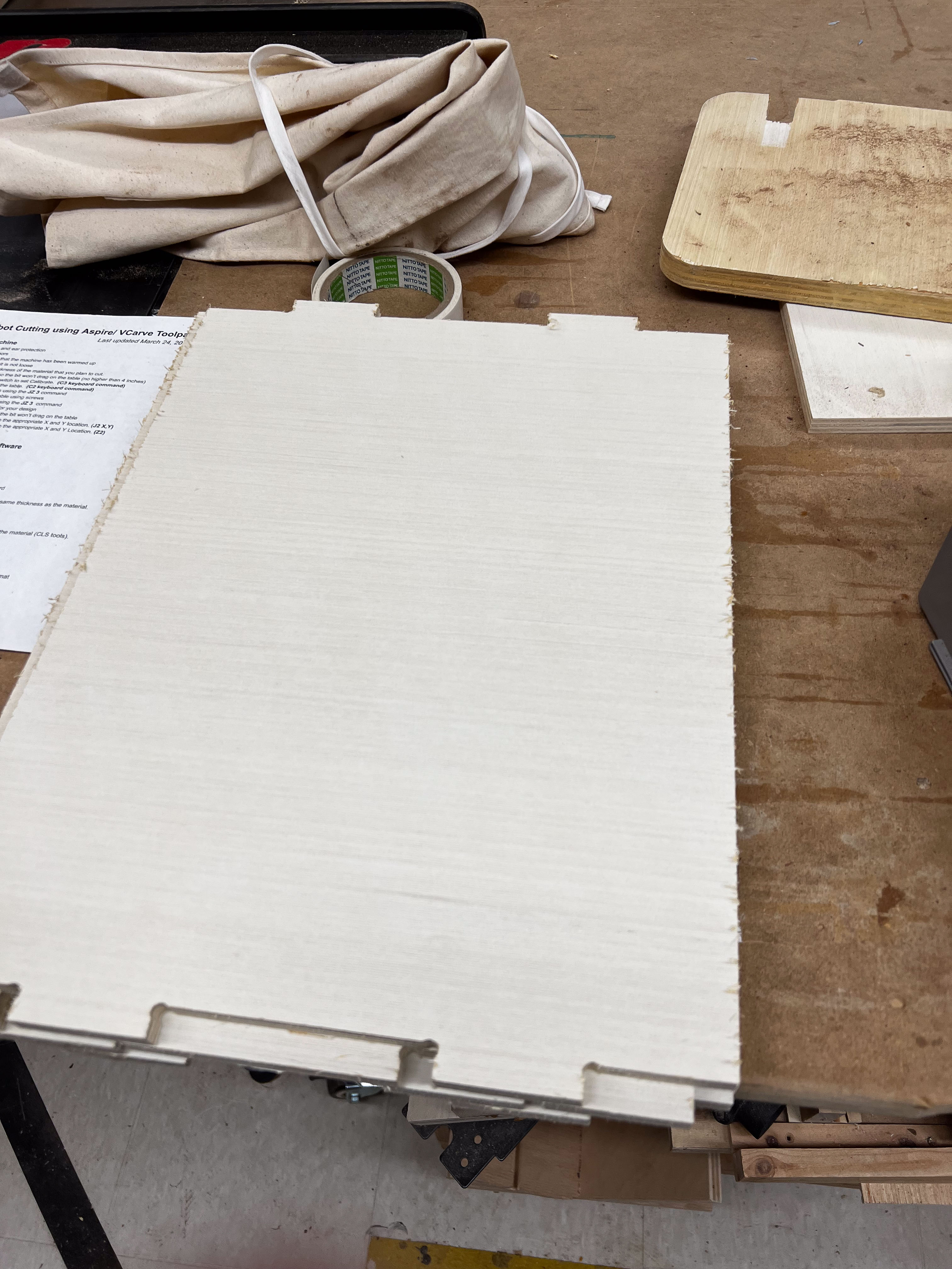
- Once the pieces were cut on the CNC it was time to assemble them.
- Here are assembly pictures.
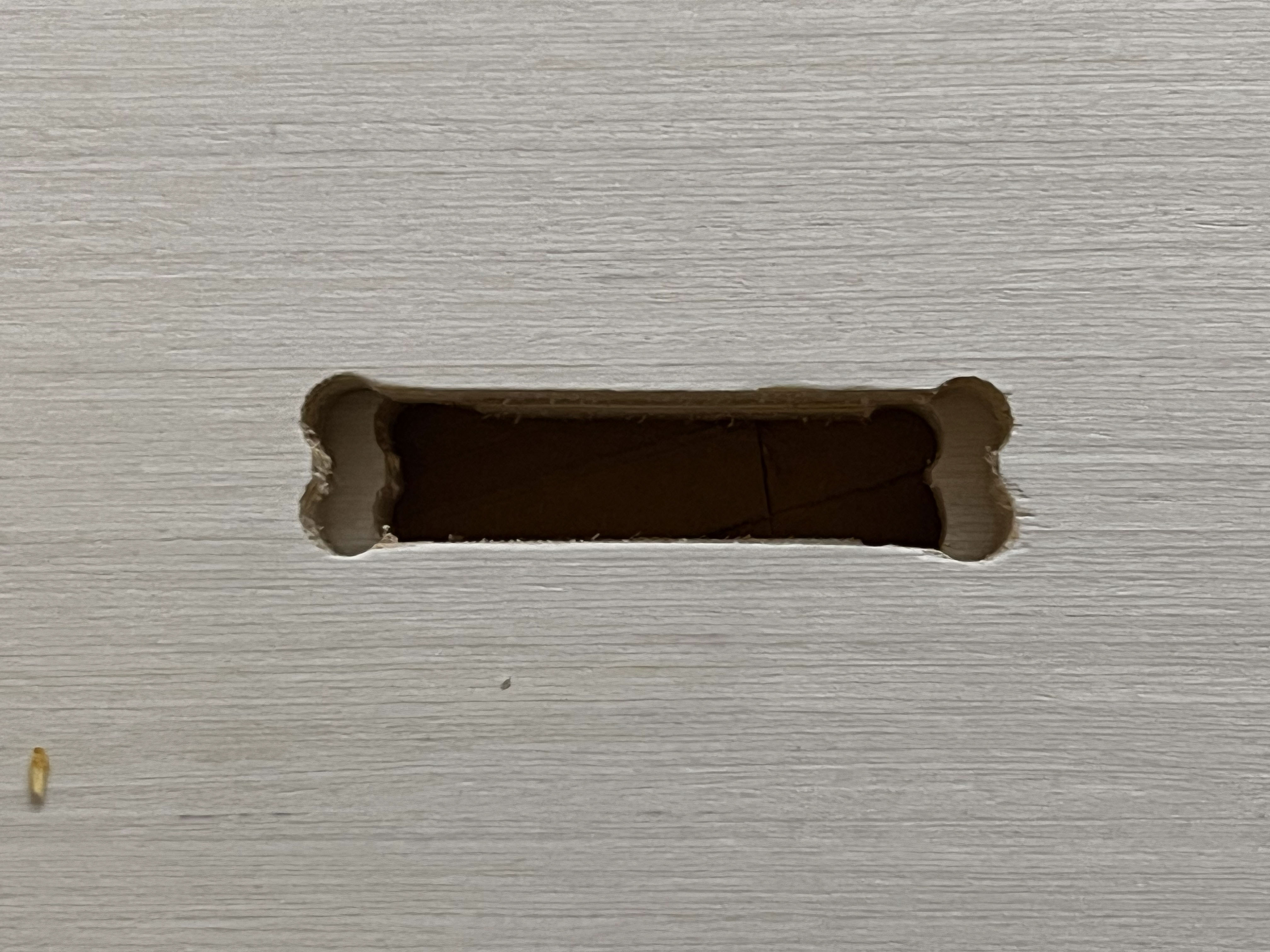
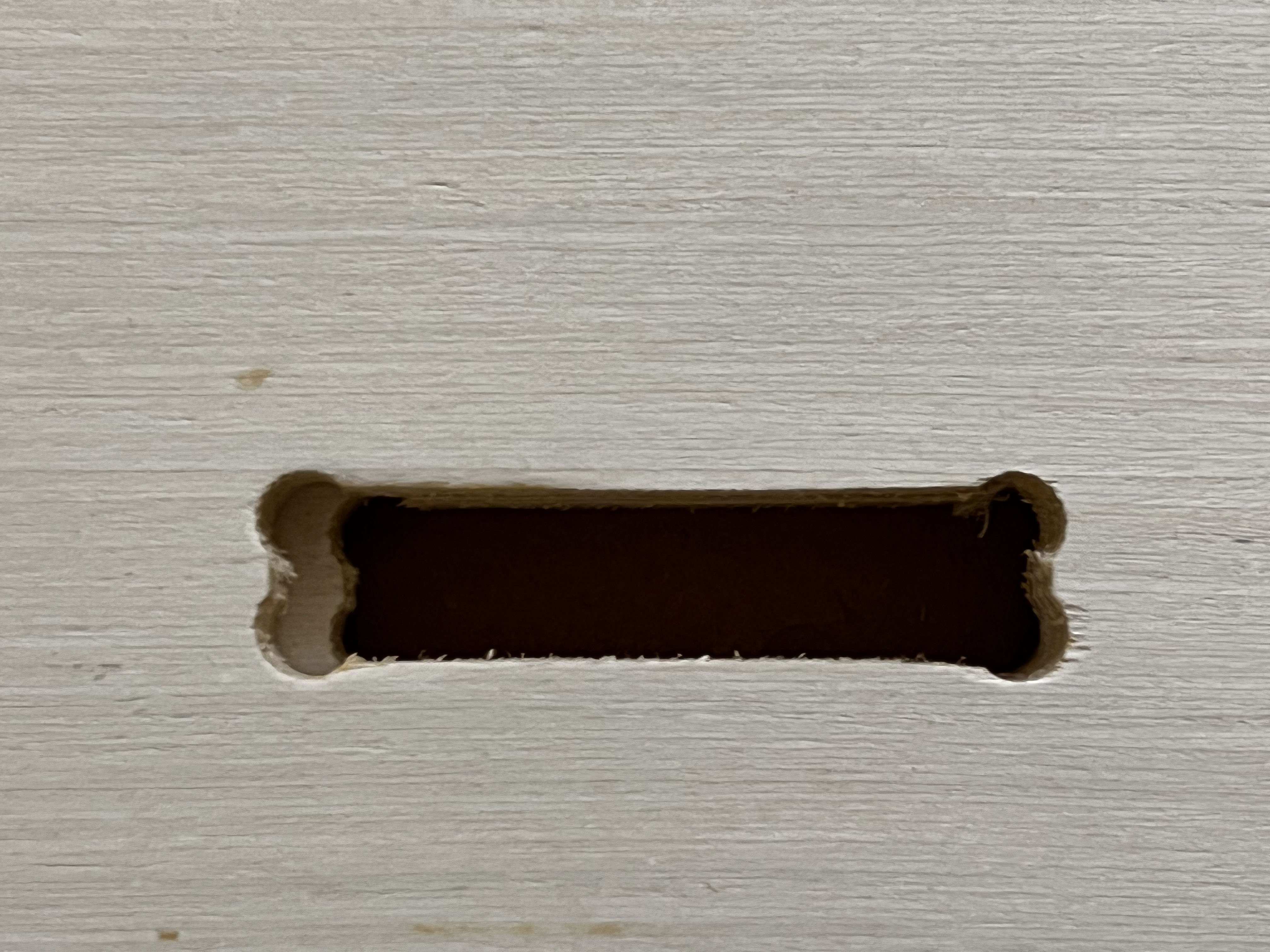
- I stacked the two side pieces on top of each other and realized that the one of the dogbones weren’t the same on both pieces, so I need to rework it a bit. I used a cordless drill with a 3/8” bit to expand the dogbone to make it match. I also used the correct piece as a template when drilling.
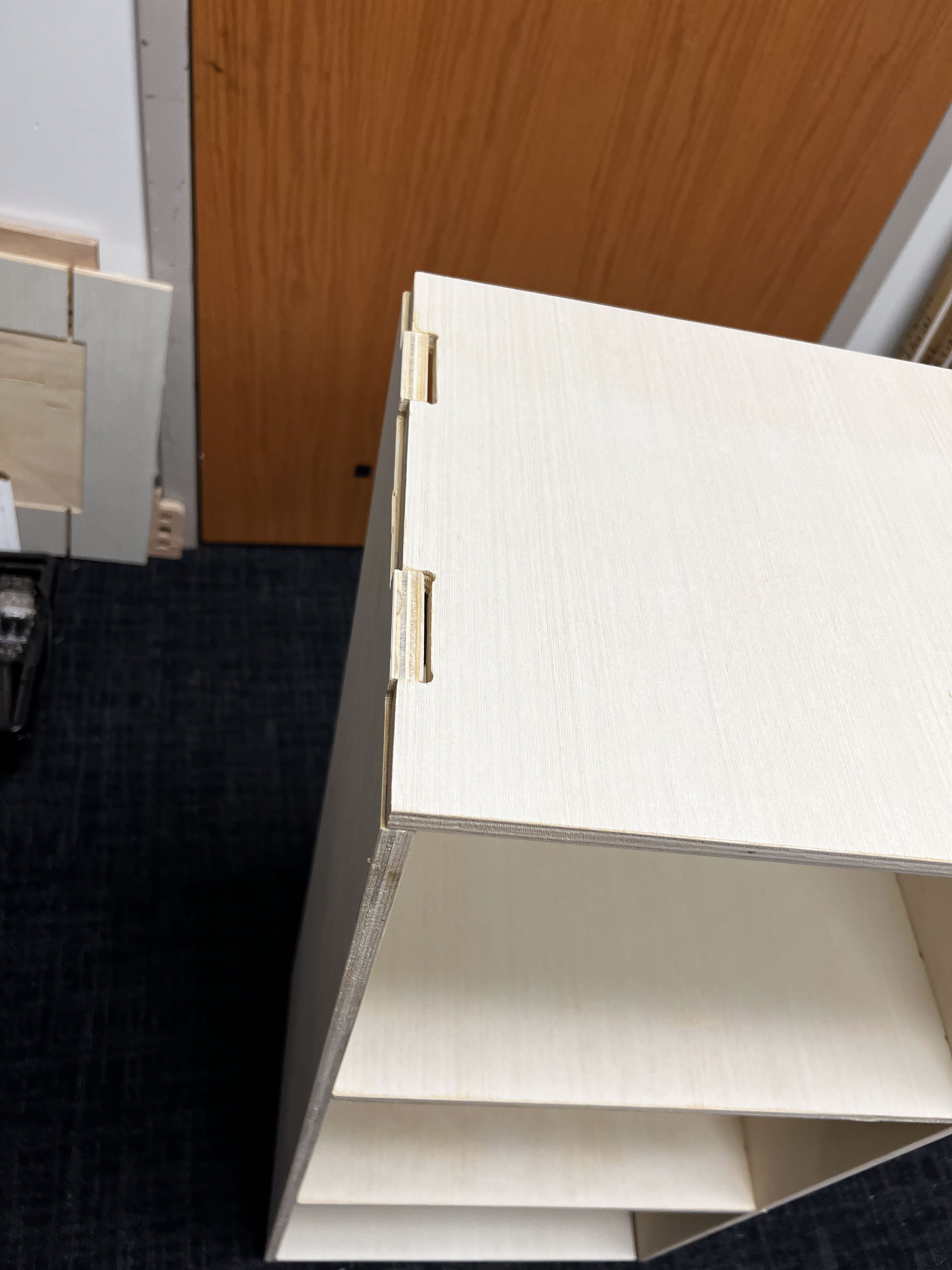
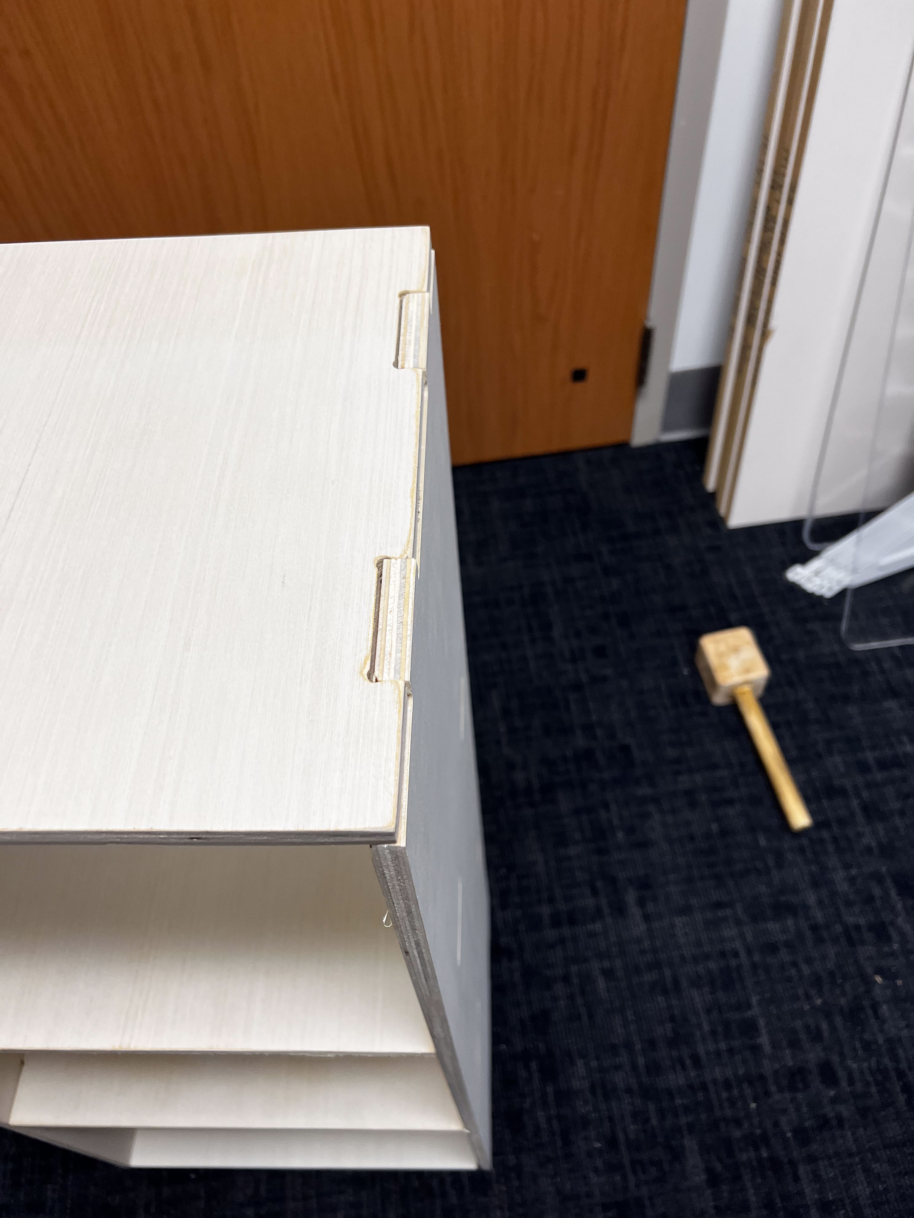
- Once the dogbones were corrected, I assembled the shelves with a wooden mallet, and they generally fit well. As you can see from the pictures below, there was a slight bow in the wood with a slight gap on the top.
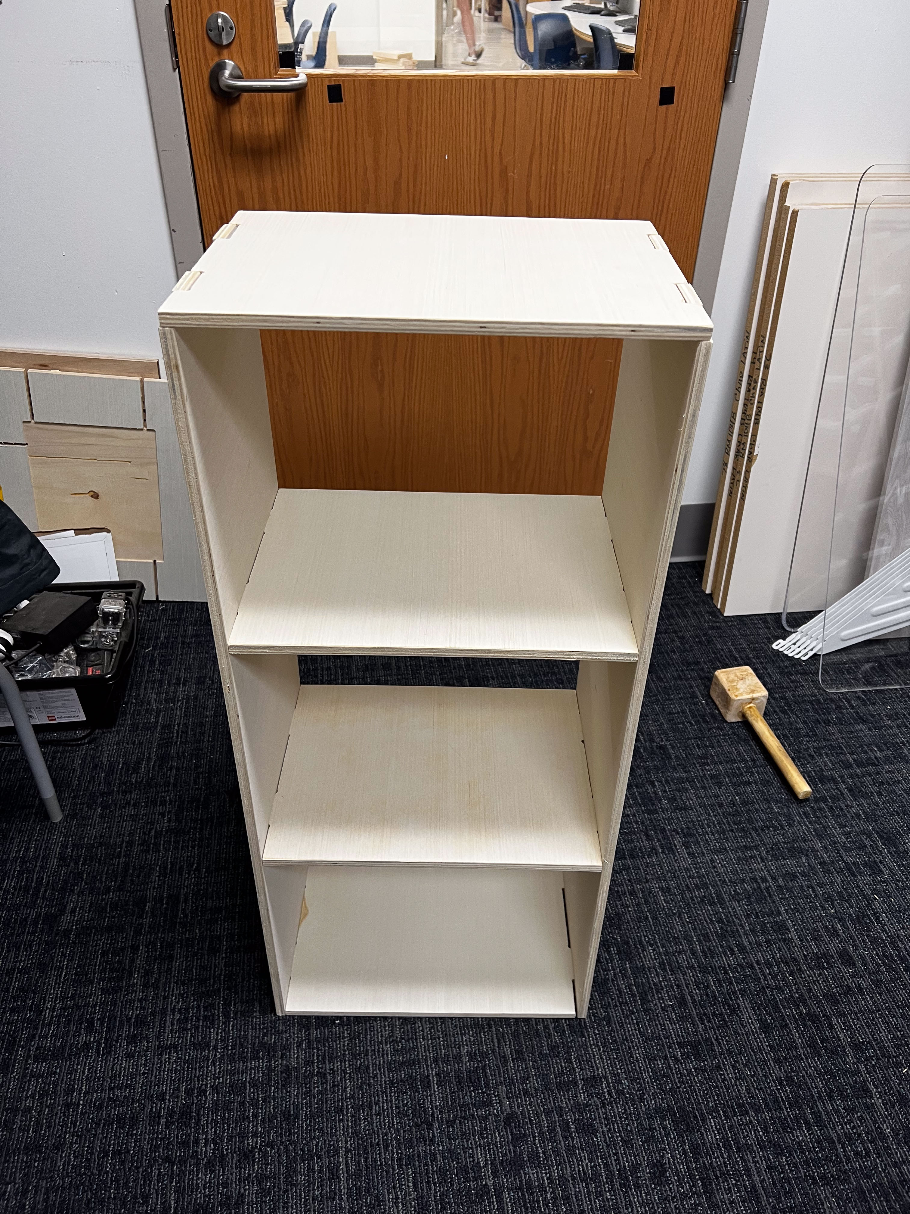
- Here is a picture of the final assembled shelves.
Learning
Overall this assignment allowed me to improve my CAD skills and learn more about the capabilities of the ShopBot CNC. I learned about assemblies and lie flat commands in Fusion 360 and how to make complicated toolpaths in Aspire to use in the ShopBot. While the slight interference fit I planned for generally worked with the final assembly, the bow of the wood allowed for some slight separation. Next time I will take into account the bow of the wood when assembling. If I had switched sides for the end pieces, it may have worked better.
Link to my files for the week.
Group Assignment:
Link to our group assignment.