3. Computer-Controlled Cutting
Individual assignment:
-
cut something on the vinyl cutter
-
design, lasercut, and document a parametric construction kit, accounting for the lasercutter kerf, which can be assembled in multiple ways, and for extra credit include elements that aren’t flat v2. Construction Kit
Vinyl Cutter
-
CorelDraw
- I’m a lifelong Cubs fan, so I’ll make a Cubs sticker for my laptop.
- Find a design online that I can trace in CorelDraw.
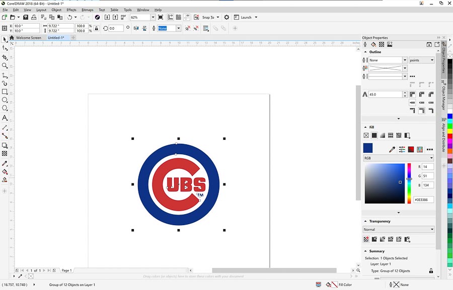
- Use ‘Trace Bit Map’ Function to outline the logo into three colors (Blue, Red White)
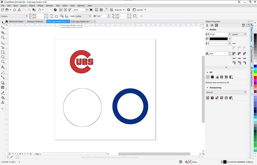
- Export the resulting file as an SVG for use on my Cricut machine at home.
-
Cricut
-
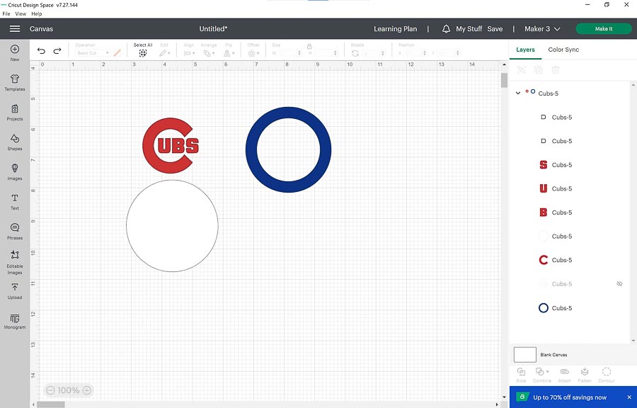
Used the Cricut Design Space software to cut the sticker. I loaded the SVG into the DesignSpace software and here is how it came out.
-
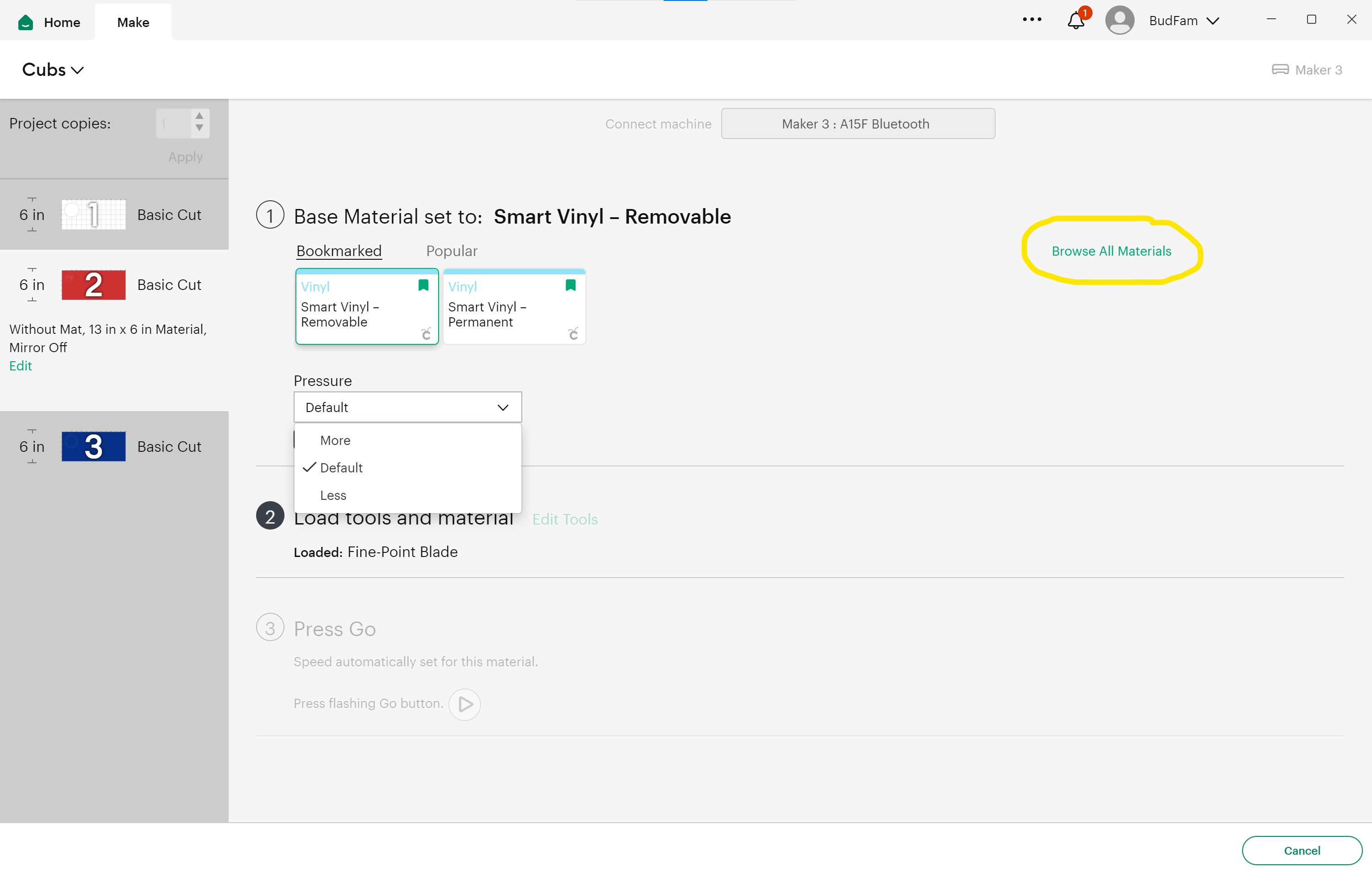
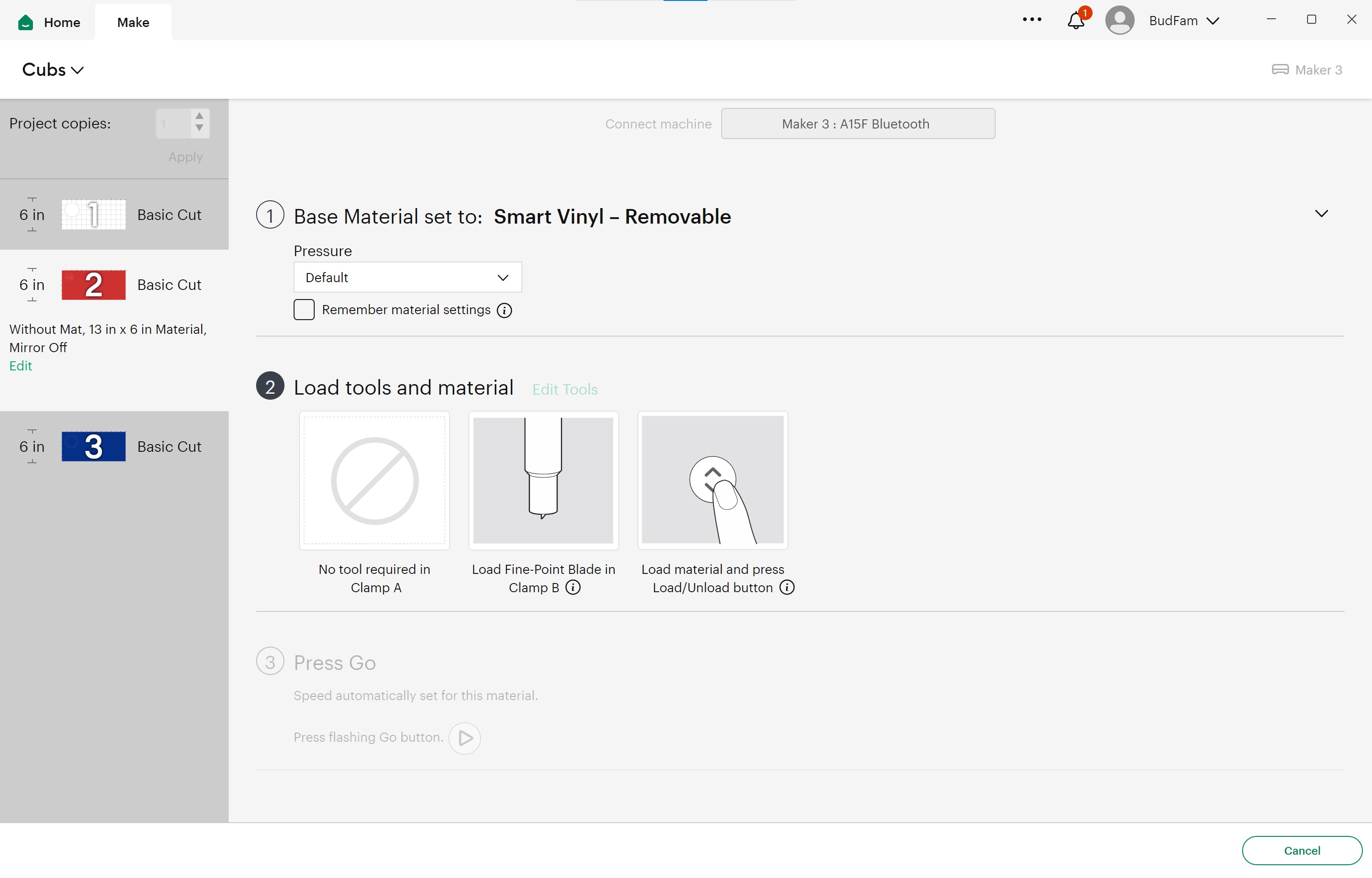
Once that was done, I selected “Make It” in the upper right corner of the screen and this was the result.
-
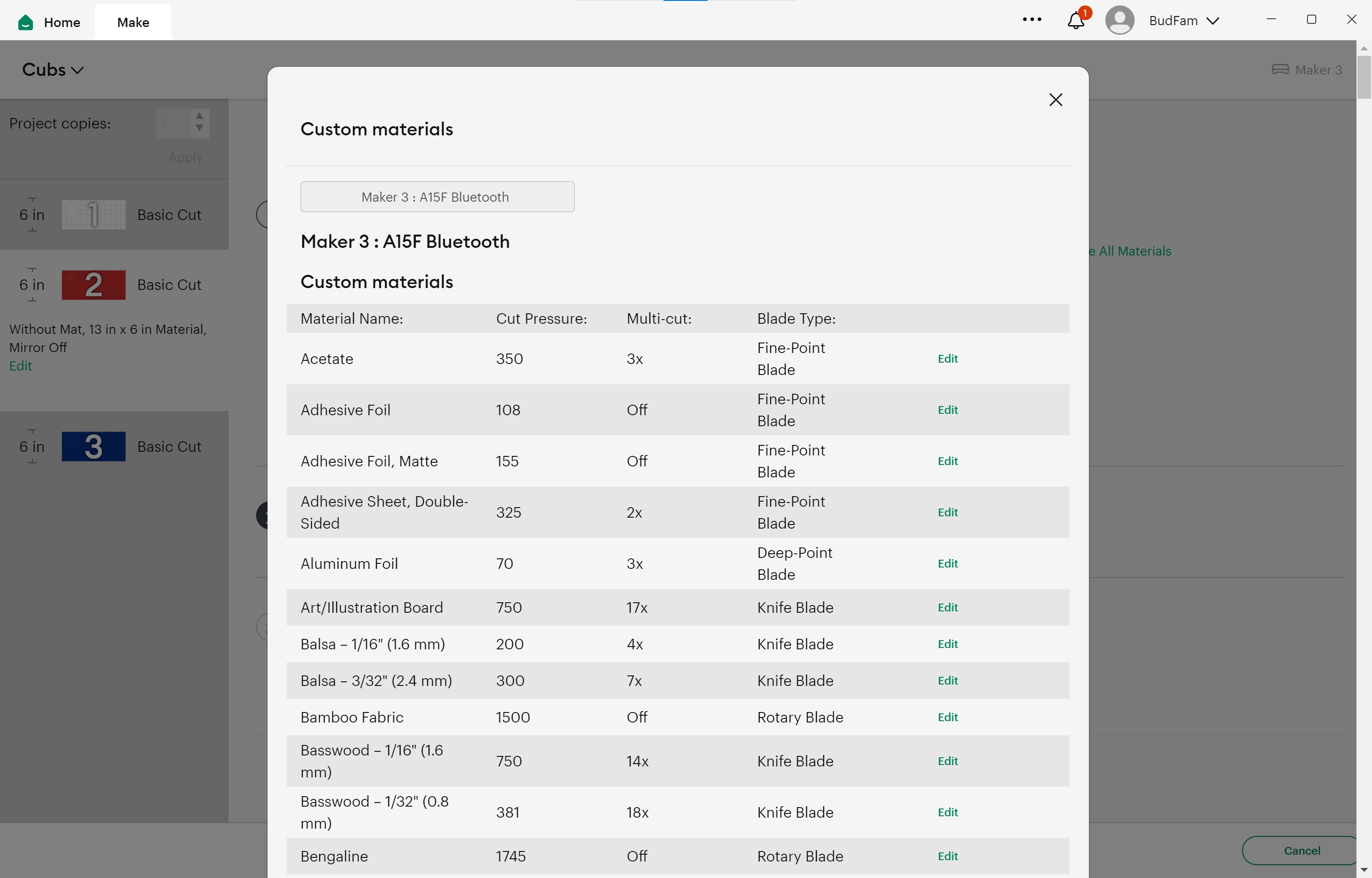
The material I used was the SmartVinyl-Removable which is shown as being bookmarked, and the pressure was “Default” with the “Fine-Point Blade.” If you would like more options for cutting, click on the “Browse All Materials” link and the following screen comes up which shows the setting for each of the materials in the Cricut library.
-
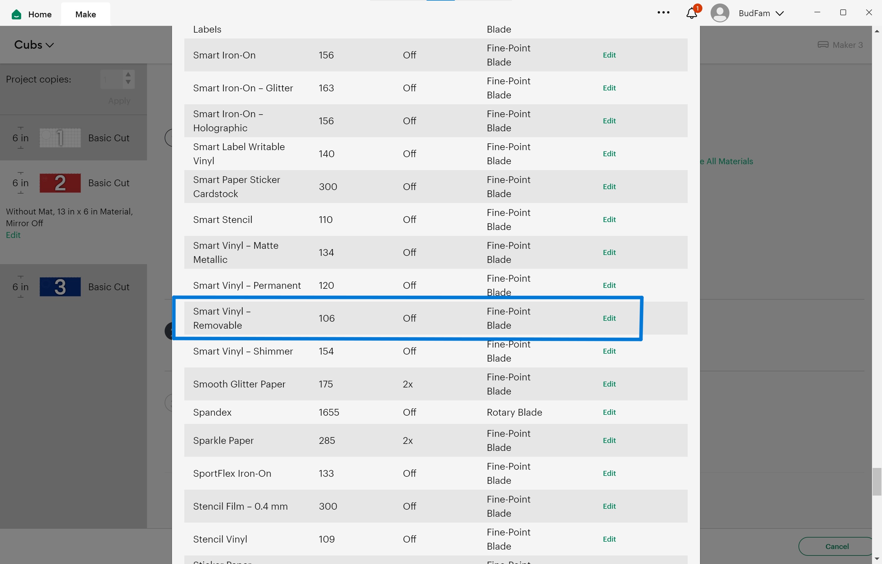
Here are the settings for the SmartVinyl-Removable I used for this project. The cut pressure was 106 with a single pass of the Fine-Point Blade.
-
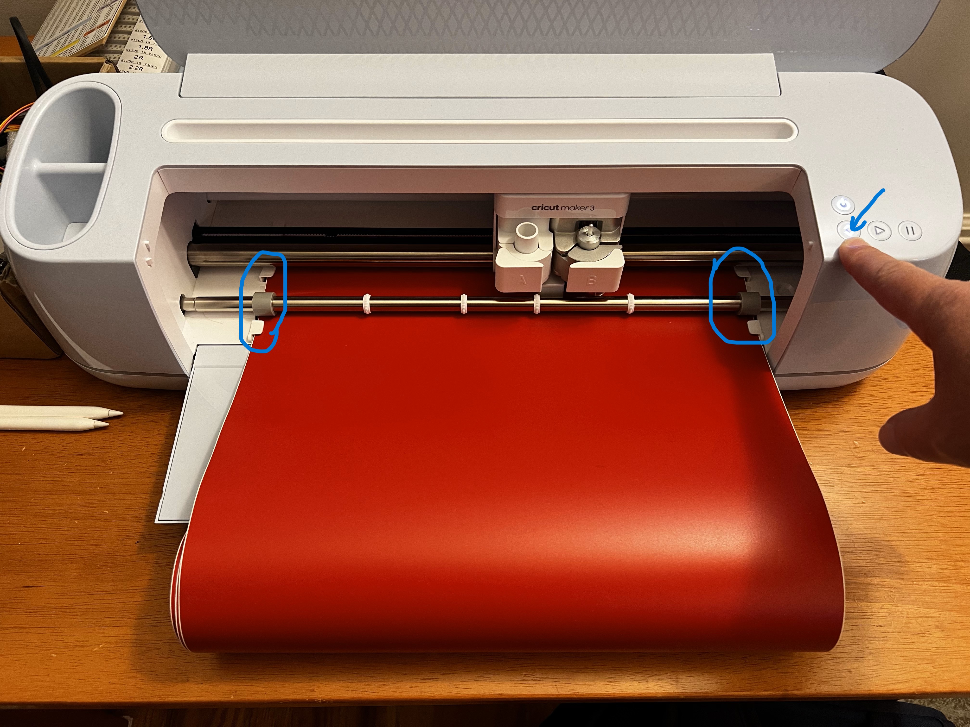
I found the SamrtVinyl without a cut mat difficult to load correctly. I don’t have a cutmat, but the machine is supposed to work without it, so that is the option I selected. After some trial and error, I was able to get it loaded. The critical part of loading was being sure the roll was evenly loaded and under the loading guides before pressing the “Load” button.
-
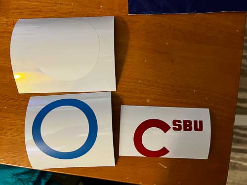
After I double checked the proper tool was loaded, I pressed “Go” on the machine. The sticker did cut, but not exactly in the order I thought they would. The letters for Cubs are all individual cuts, so I’ll have to line them up manually.
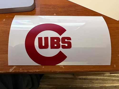
- Cubs lettering arranged correctly.
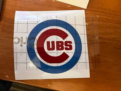
- Layered with transfer tape.
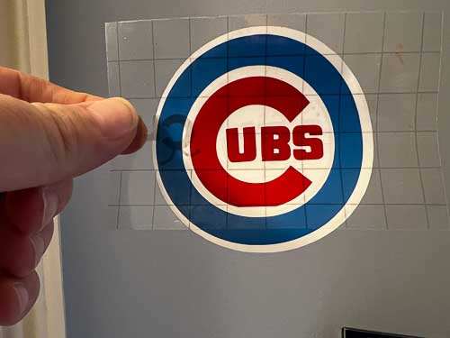
- Finished!
-
Construction Kit
-
I took this assignment as an opportunity to familiarize myself with the parametric modeling features of Fusion360. As I watched Neil’s lecture for the week, I started thinking about how I could incorporate as much parameterization as possible in my design. My goal was to have as much flexibility in my fusion 360 design as there was in my Cuttle design was last week. While I definitely didn’t achieve my goal, I was able to learn a lot along the way. Here’s what I did.
- After watching some of the Saturday’s recitation with Adrian, I did a quick search of living hinges in Fusion 360 for inspiration on what might be possible. I found this video: Living Hinges in Fusion 360
- I watched the video. It demonstrated a few useful features of Fusion 360 that I will keep in mind.
- The ability to “Unfold” a sheet metal design to simulate a living hinge for laser cutting
- The ability to model 1/8” plywood bending parameters such as minimum bend radius
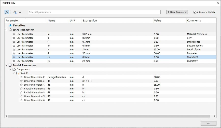
- Where the “Change Parameters” utility is in Fusion 360 (Under the Modify menu) and the basics of how to use it. Most importantly, how to add user defined parameters.
- Time to work with Fusion 360
- Here was the general plan for what I hoped to accomplish in Fusion 360:
- Make a rectangle with user definable side lengths
- Extrude the rectangle to make it a 3D model
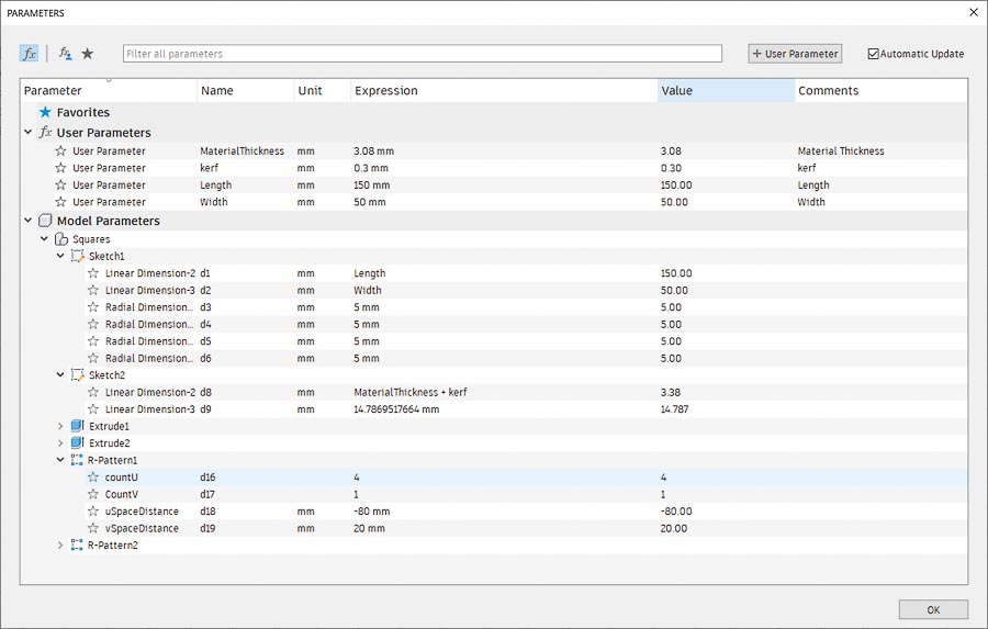
- Make a sketch of the press-fit joint that had user definable (aka parametric) features such as joint opening, joint depth, kerf, and interefence.
- Extrude the press-fit joint to make a cutout of it in the model
- Propagate the press-fit joint throughout the model with the “Circular Pattern’ Feature in the Solid menu.
- Make multiple copies of the model for lasercutting using the “Rectangular Pattern” tool.
- Test out the parametric feature I design by changing a feature in the “Changer Parameters” tools and see what happened. Adjust as necessary.
- Export the design to DXF for importing to CorelDraw and send to the Epilog lasercutter for cutting.
-
Here’s how it worked out
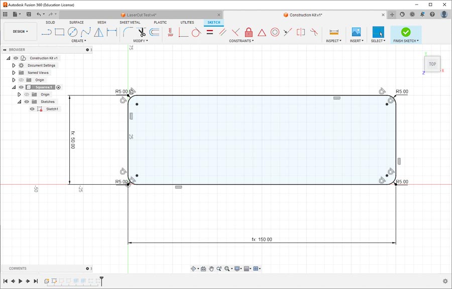
- Made sketch of base design rectangle in Fusion 360
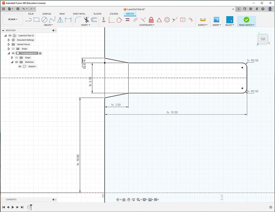
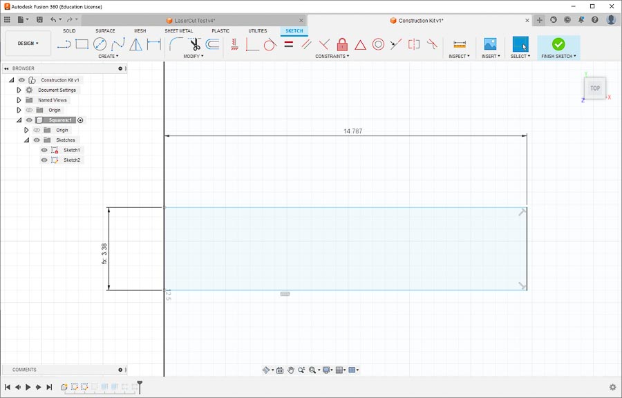
- Made sketch of basic press-fit slot joint
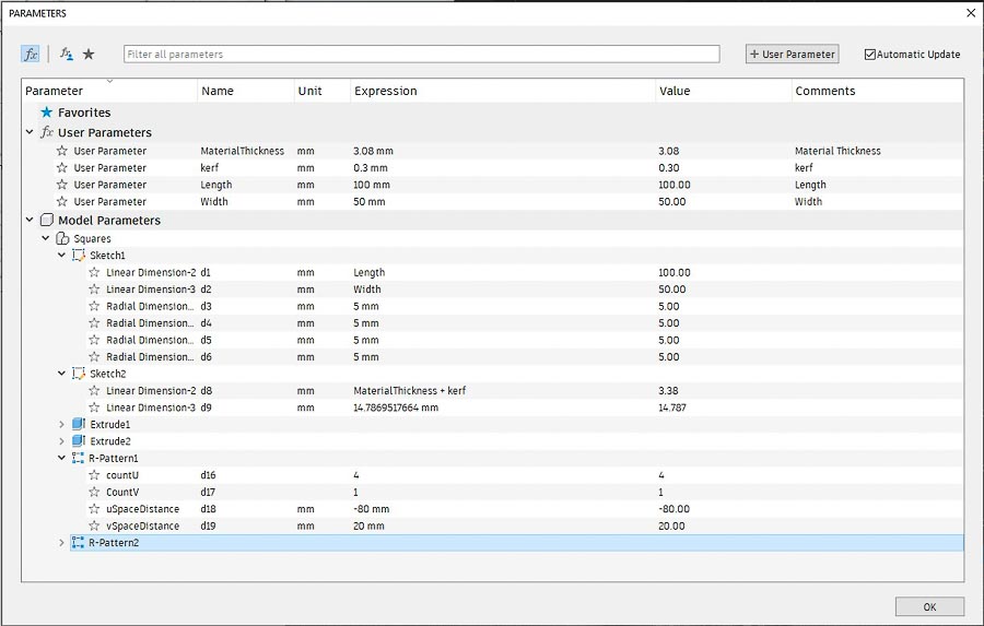
- Went under the ‘Modify’ menu to ‘Change Parameters’ tool to setup ‘’User Parameters’ to test the parametric features of Fusion 360.
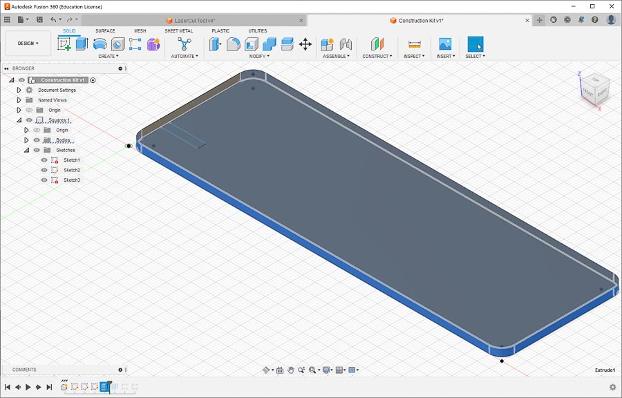
- Extruded rectangle to model cardboard
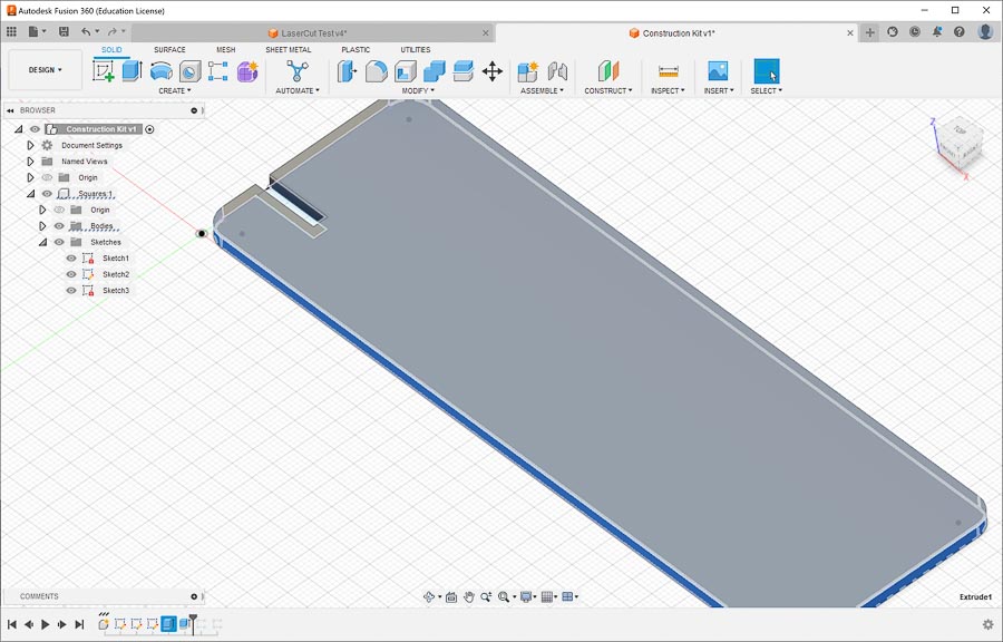
- Added press-fit joint cutout
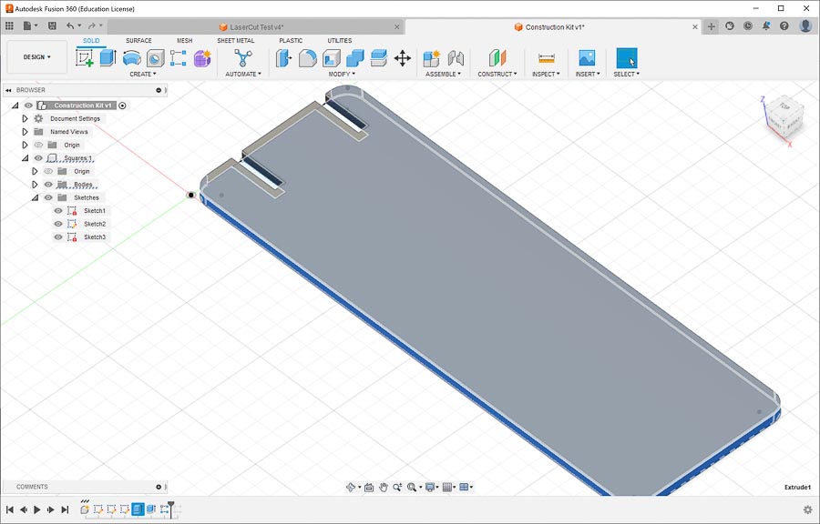
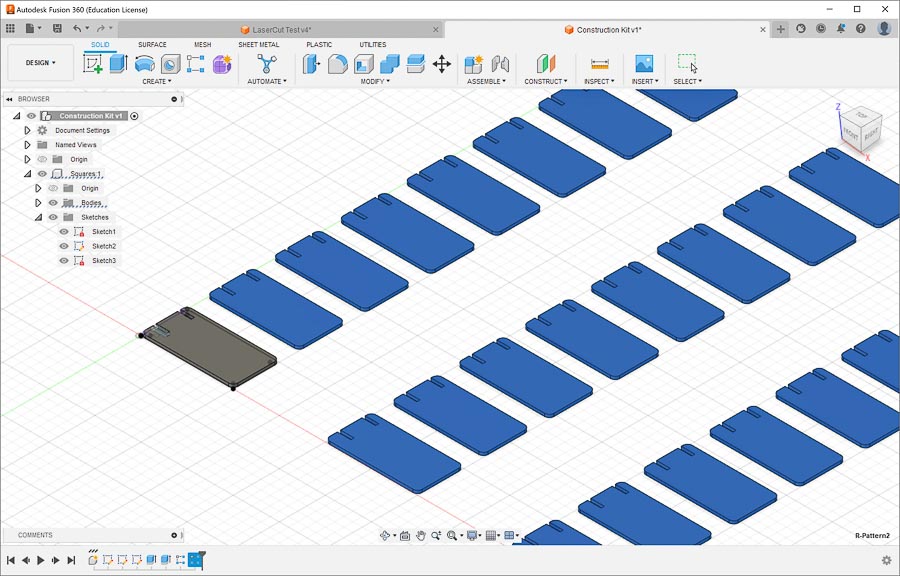
- Experimented with Rectangle Pattern tool to add additional press-fit joint
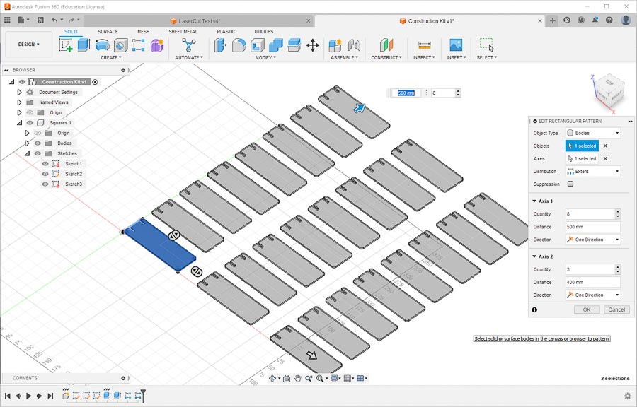
- Using the Rectangular Pattern tool was able to make an Array of pieces for the kit. I’m on a roll.
- For fun tried varying the length of the pieces from 150mm to 100mm with the ‘Change Parameters’ tool.
- The successful result!
- At this point I got a bit too fancy and tried to change the underlying sketch to mirror the slot on the short side of the model to make them equidistant from the centerline of the short side. The result was a massive failure that said “Compute Failed” I mildly panicked and tried a few different things that only made it worse. I was in troubleshooting mode and forgot to take screenshots. It eventually resulted in red failure colors on the extrusions features of the parametric timeline in Fusions360 along with missing models and a blank canvas. I tried various strategies to undo the mistake in the parametric timeline to no avail, but eventually was able to ‘Ctrl+Z’ back to a useable file.
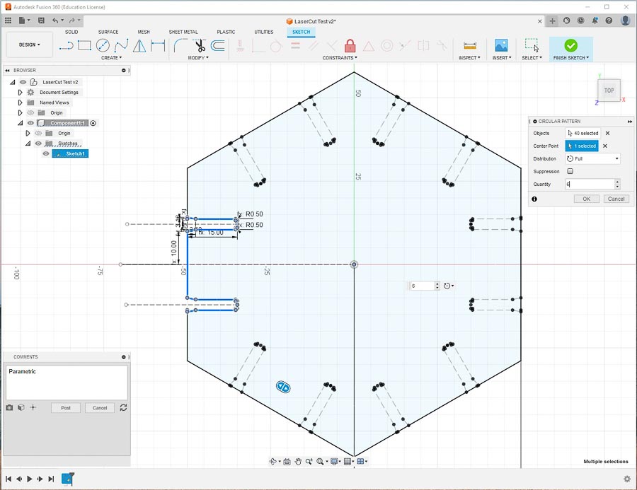
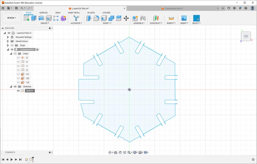
- After that excitement, I decided to try my next experiment on adding additional press-fit joint parameters in a new model. I went with a hexagon shape and would use centerlines, mirrors, and a circular pattern array to make the pres-fit joints. My ultimate goal was to have a design process that resulted in a DXF that could be exported to CorelDraw with no retouching necessary for lasercutting.
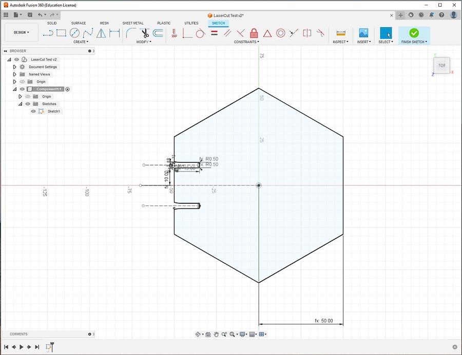
- First I made a basic circumscribed hexagon and then designed the basic press-fit joint with use parameters.
- I then mirrored the joint along the centerline of one side of the hexagon.
- I tried to use the Circular Pattern Tool to add the press-fit join to the other sides of the hexagon, but ran into an issue because I didn’t copy all the construction and reference lines. When I tried to update the joint by changing parameters I received a ‘Compute Failed’ error.
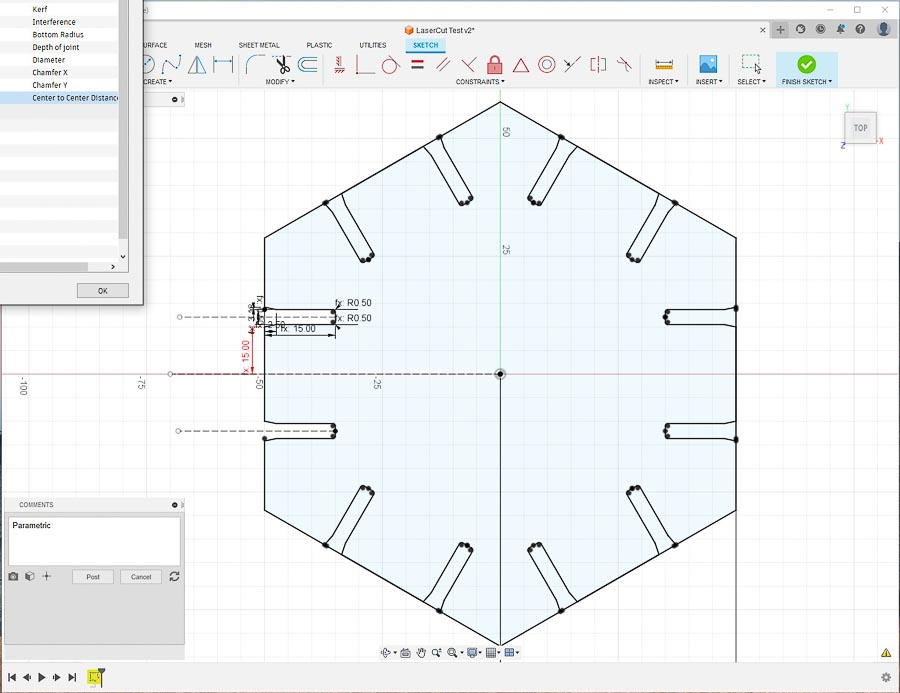
- I then tried again, but this time included all the construction lines in the Pattern Tool and it seemed to work.
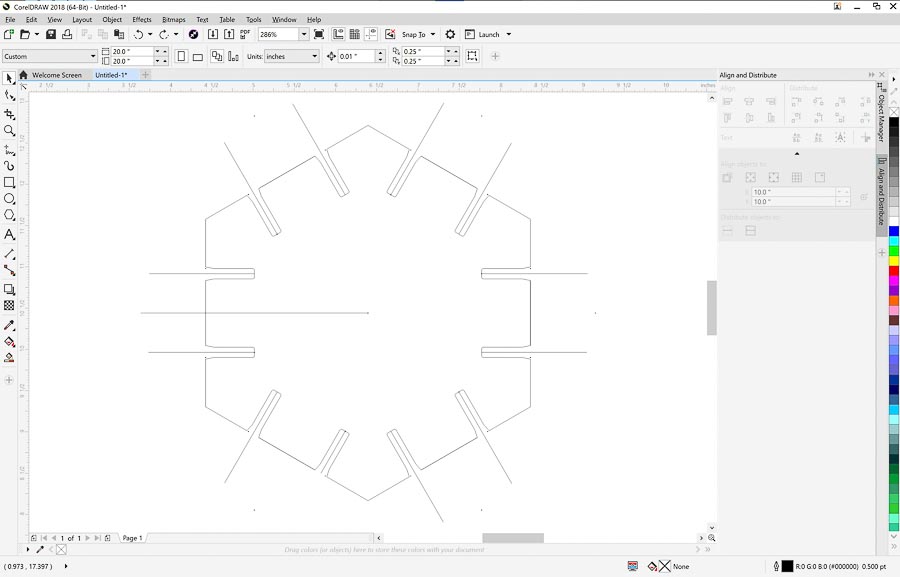
- After all that work I was satisfied enough to try the export process to see if I could directly export my file as a DXF and have it work on the laser cutter without retouching it. Here is how the file looked when imported into CorelDraw.
-
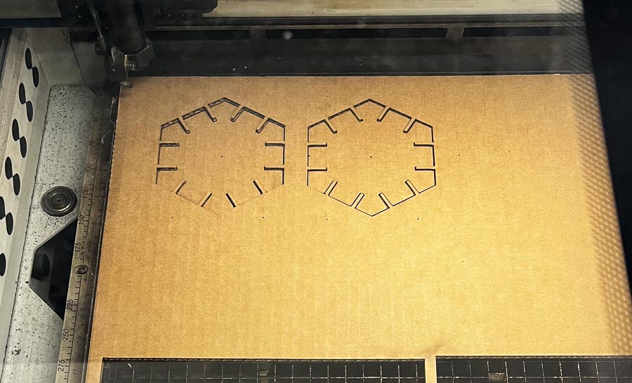
The construction line were an issue with my goal, so went back and removed them from the sketch and reexported the file as a DXF, and it worked, so I went ahead and cut them on the lasercutter.
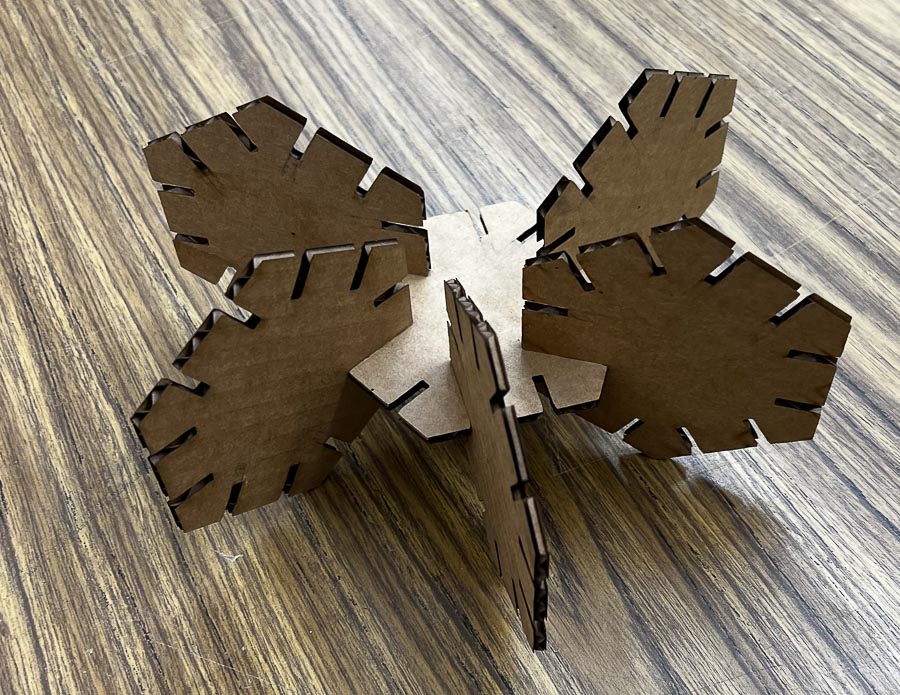
 And put together. The chamfer on the press-fit joint worked really well and has a snug fit, but can still be easily disassembled.
-
Now it was time for another iteration for fun. This time I was going to try to change the size of the hexagon. It didn’t work. I think when I deleted the construction lines for the DXF export, I lost some key reference lines and that may have been the issue. I will continue to work on it, but have run out of time to keep working at it for now.
- Made sketch of base design rectangle in Fusion 360
- Here was the general plan for what I hoped to accomplish in Fusion 360:
- I watched the video. It demonstrated a few useful features of Fusion 360 that I will keep in mind.
- After watching some of the Saturday’s recitation with Adrian, I did a quick search of living hinges in Fusion 360 for inspiration on what might be possible. I found this video: Living Hinges in Fusion 360
-
Learning-I learned about parametric design and the different ways to used it in Fusion 360. I was able to understand the basics fairly quickly, but stumbled a bit with the more intricate parts of properly setting up construction lines and reference points when adjusting the parametric parameters after making a pattern array. I was able to export and DXF file from Fusion 360 and use it in CorelDraw with no touch up necessary before laser cutting.
-
Things to improve upon-while I have the basic parametric theory down, I have work to do when making the parametric parts of the design more complex.
Link to the files for the week