4. Embedded Programming
Individual assignment:
Use the following microcontrollers (RP2040, Arduino, ATTiny412 or ATTiny1614) Have them blink a light and another task and try to add an input using C++ (Arduino) and Python(Thonny).
RP2040 Raspberry Pi Pico
Using Arduino and C++
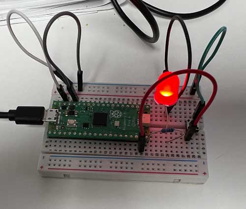
- I’m using the Raspberry Pi Pico installed on a small breadboard that we have in the lab for this part of the assignment. I’m also using the Arduino IDE 2.0.3 and Thonny 4.0.2 and following the tutorials from our instructors.
- One important initial part of the assignment was to add the RP2040 board to the Arduino IDE. Dan Stone helped me navigate that process.
- Once the RP2040 board was available the next step was to connect the board to my PC via the USB port. The key step was to hold down the ‘BOOTSEL’ button while plugging it in to my computer, and now it comes up on COM8.
- Got the RP2040 to blink and went in the Arduino IDE and changed the blink rate and uploaded the code to run it again. Received an upload error that was corrected by pressing the reset button on the Pico and inserting the USB at the same time.
- Next step was to set up an external LED and switch the output from the built-in LED to the external one. Adam Durrett assisted me with some troubleshooting for switching to external LED for this task.
#include <pitches.h>

/*
  Blink

  Turns an LED on for one second, then off for one second, repeatedly.

  Most Arduinos have an on-board LED you can control. On the UNO, MEGA and ZERO
  it is attached to digital pin 13, on MKR1000 on pin 6. LED_BUILTIN is set to
  the correct LED pin independent of which board is used.
  If you want to know what pin the on-board LED is connected to on your Arduino
  model, check the Technical Specs of your board at:
  https://www.arduino.cc/en/Main/Products

  modified 8 May 2014
  by Scott Fitzgerald
  modified 2 Sep 2016
  by Arturo Guadalupi
  modified 8 Sep 2016
  by Colby Newman

  This example code is in the public domain.

  https://www.arduino.cc/en/Tutorial/BuiltInExamples/Blink
*/

// the setup function runs once when you press reset or power the board
void setup() {
  pinMode(15, OUTPUT);  // set output to pin #15 with the Red gundrop LED
  pinMode(14, INPUT);   // set input to the button
  Serial.begin(9600);
}

// the loop function runs over and over again forever
void loop() {
  if (digitalRead(14)==HIGH){
    digitalWrite(15, HIGH);  // turn the LED on (HIGH is the voltage level)
    Serial.print("pressed\n");
    }
  else{
    digitalWrite(15,LOW);
    }
  delay(50);
}
-
Was able to add an external LED, push button input and serial output back to the computer monitor when the button was pushed.
Using Thonny IDE and MicroPython
- I followed the tutorial given to use from Dr Taylor to setup Thonny and MicroPython on my laptop so I could experiment with the Thonny and MicroPython environment.
- I used the tutorials to learn how to use a Raspberry Pi Pico to blink the internal LED, an external LED, use a PIR (HC-SR501 PIR Sensor) input sensor to drive a flashing light and a networked output on the serial monitor of my laptop.
- I wanted to learn how to use the PIR sensor in order to integrate it into my final project as an input sensor that will trigger the pump to start on the stroller cooler.
- Overall it was a fairly straightforward process, but I made some adjustments to the PIR sensor to decrease the sensitivity and add a counter to the serial monitor output to see how often the sensor was triggered.
import machine
import utime

sensor_pir=machine.Pin(28, machine.Pin.IN, machine.Pin.PULL_DOWN)
led=machine.Pin(15, machine.Pin.OUT)
count = 0

def pir_handler(pin):
    global count
    utime.sleep_ms(100)
    if pin.value():
        count += 1
        print("ALARM! Motion detected! Count:", count)

        for i in range(50):
            led.toggle()
            utime.sleep_ms(100)

sensor_pir.irq(trigger=machine.Pin.IRQ_RISING, handler=pir_handler)

while True:
    led.toggle()
    utime.sleep(1)
-
Here’s a photo and video of the sensor in operation.
-
One learning I had was that I needed to reinstall MicroPython on the Pico when I switched back from using the Pico with Arduino.

Link to my files for the week.
Group Assignment
Link to our group assignment.
References for the week
- Charlie Horvath Embedded Programming Week 8
- ChatGPT
- David Taylor’s MicroPython slide deck.