6. Electronics design
This week we started off by surface mount souldering with a XIAO Board using Adrians board that Dr. Taylor addapted into Eagle. Then I used that board and created a single use board in Kicad and Eagle. For the group work we tested the XIAO Board using a Multimeter and a Oscilloscope, I helped Griffin with the multimeter.
XIAO Board
XIAO Board Layout
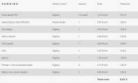
Mr. Budzichowski milled the XIAO Boards for us then I collected all of the components I would need for soldering the board. This is a spread sheet I got off of Adrains site:
I then tapped all of them on a sheet of paper so I knew what each piece was and so that they would all stay together. You can see that piece of paper here:
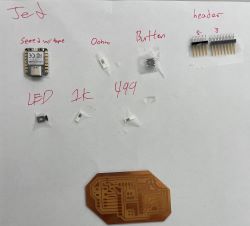
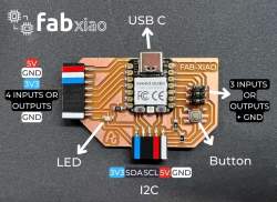
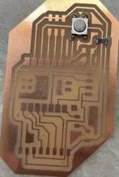
Then using this layout image I got on Adrians site I started souldering. One thing to note though is that resistor that has numbers 102 is the 1k ohm resistor, and the resistor that is 471 is the 499ohm resistor. Heres the layout image:
Soldering the XIAO Board
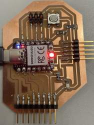
Using the layout image above I started soldering pieces one by one. When I’m surface mount soldering, I solder 2 ways depending on what the component is. For the resistors and leds I first aplied a small amount of solder on one end of the traces, then using tweezers I held the resistor or led so that one end touched the solder and the other end touched the other trace, then held it there until the soldering iron heated the solder up to a point where I could shove the component into place with the tweezers, then I held the iron to the other trace and the other end of the compentent and just added a little soulder there. But for the headers and Xiao, I soldered them as if the were through hole, I taped the Xiao to the board and added solder to each pinout and for the headers I did the same but I had to hold the them in place with tweezers for the first connection.
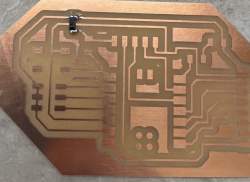
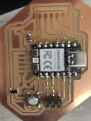
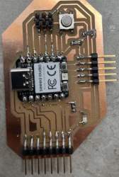
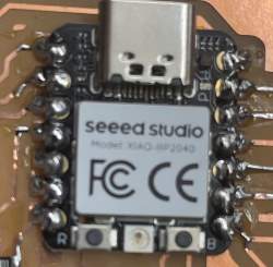
Here are the progress images:
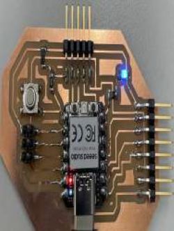
Working
Here you can see the Blue LED on the Xiao and then the Blue LED on the pcb board. I used the basic blink code thats in the Arduino IDE examples, for the Xiao LED I didn’t edit the code, and using pin 0 I got the board blinking.
Developing a Board
For my single use Board I am going to use the XIAO to access the RP2040 and I am going to use a LCD screen. Back in week 4, I used the Raspberry Pi Pico to code a LCD screen. So I will be using the same code and circuit plan for my board.
KiCad
KiCad is a software I’ve used before and I liked. In KiCad you can create schematic that can link up to a PCB editer and there is a 3d view tool that I think is helpful for getting a feel of you board.
KiCad Libraries
In KiCad I needed to download a library for the Xiao board. I downloaded this library that Ryan gave me so I could access the board. I then cliked prefernces on the control panal and clikced Manage Symbol Libraries then clicked the small folder icon below the big table and imported the library. I then clicked on the Manage Footprint Library and did the same thing as the Symbol Library.
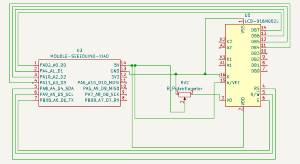
Kicad Schematic
Using the Add Symbol Tool I ckicked the schematic canvas and it brought up a search bar where I could look for my pieces. I added the “Display:LCD-016N002L” for my LCD screen I added the “Potentiometer_SMD:Potentiometer_ACP_CA6-VSMD_Vertical_Hole” for the 10k potentiometer. And finaly the “Xiao_PCD:MOUDLE14P-SMD-2.54-21X17.8MM” for the Xiao board. I then looked at my pinouts for both the Xiao and the LCD screen from week 4 and I used the Wire Tool and connected all everything I needed. This is what it looks like:
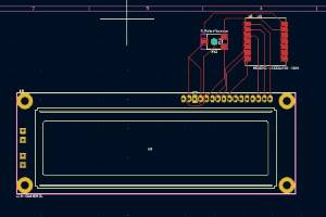
Kicad PCB Editer
Using the Kicad PCB Editor is very easy. In Kicad you can update the PCB editor with the schematic you have built in the schematic editor. I then organized each footprint how I liked it and to make the board as small as possible. After I did that I added traces everywhere, one nice feature about Kicad is that when you place a trace for pad to pad it highlights everpad that the trace is connected too. I then created a simple outline for the whole board and was doen.
Autodesk Eagle/Fusion360
Instead of downloading Eagle I used the Fusion 360 electronic design and editor. I knew I wanted to use Kicad in the future so I made a simple board in Eagle that included a Seeed Xiao Rp2040, a resisotr, a led, and a slide switch.
Autodesk Librarys
To acces the Seeed library go to this [link]. Once you’ve downloaded that folder unzip in then you can acces it in Fusion 360 Eagle. Click place component, then a box should apear and in the box a dropdown that says All Libraries, click the book to the right of the to open the library manager then at the top right you should be able to import a library.
Eagle Schematic Editor
Using the add component tool I searched for the Seeed Xiao Rp2040 after I added the library, then searched for a resisotr, a led, and a slide switch. Then to connect each component I used the Net tool under connect. One thing I really didn’t like about Eagle was it was really slow which could of been my WiFi but it was also hard to move around components after they had been placed and trying to rotate them was a pain.
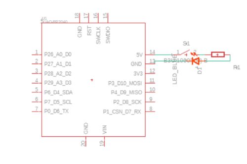
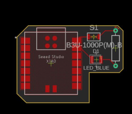
Eagle PCB Editor
The PCB was easy to use and it also auto updates form the schematic like Kicad. Routing traces wasnt hard with the manuel route tool and I think creating the board outline is easier to find because it has its own drop down named Board Shape and I created the outline useing the Outline Polyline tool. Again though moving the footprints around was a pain but here is what my board looks like.
What I Learned
This week I learned how to import libraries into KiCad and Eagle, and just how to use Eagle. I think I will be sticking with KiCad for the future.
Files
All files I created are here.