Final Project
The Compact Calendar
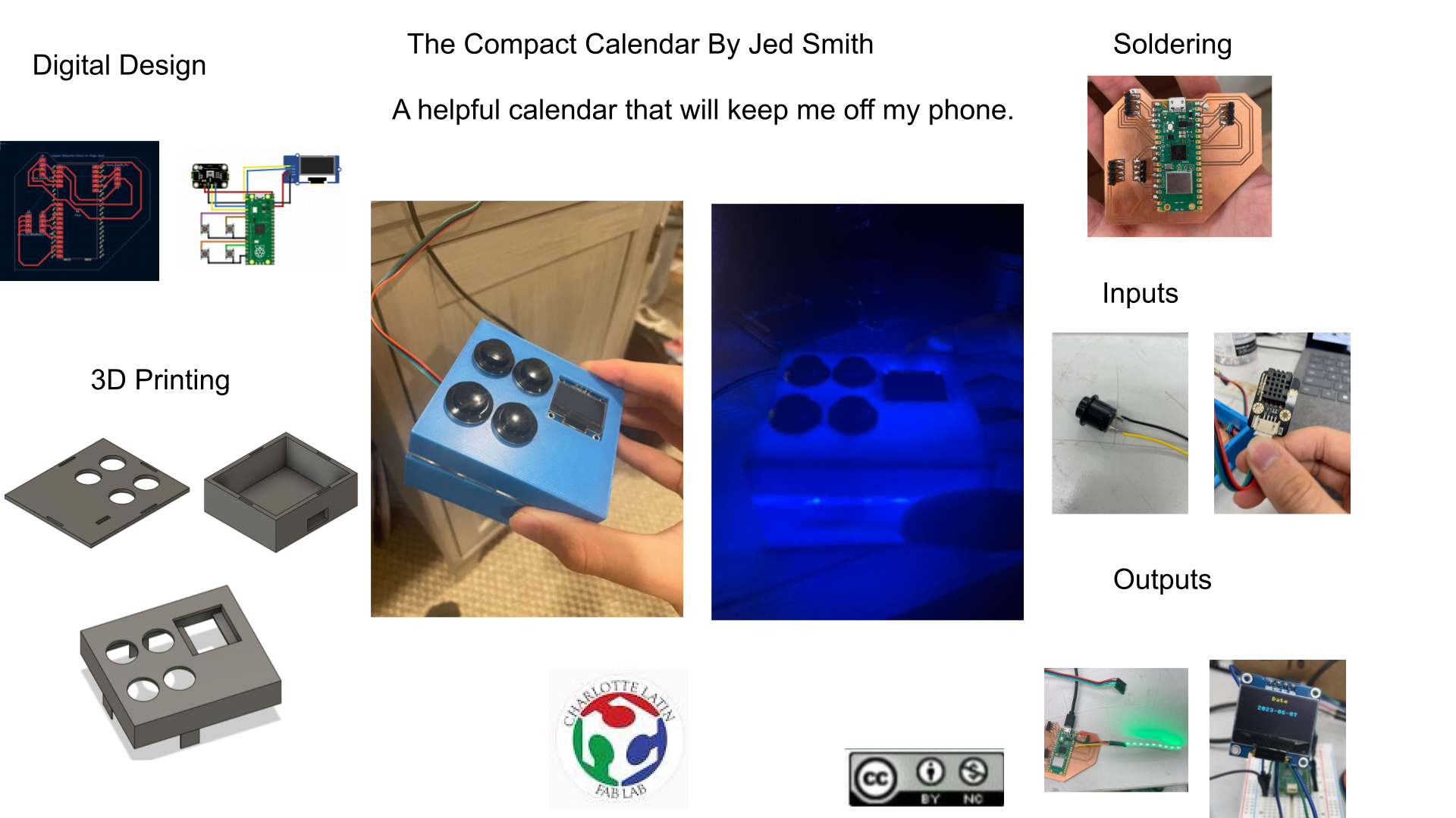
For my final project I used cad design, networking, inputs, outputs, 3-D printing, laser cutting, electronics production and electronic design.
Files
Files here.
License
Also Sceen on the slide.

Final Project Idea
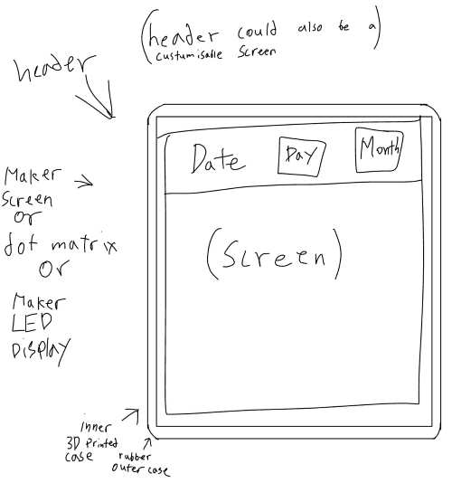
Right now for my final project im thinking about creating a single day calender that updates daily, using a digital calender and tells, me the date(month and day) and everything I have going on in that day.
This is a sketch of my final project.
| Part | Week/When I will work on it |
|---|---|
| Electronics Holder | CAD and 3d Printing |
| Calender Connection | Networking |
| Outer Case | Molding and Casting |
| Screen | Electronics and Output |
What weeks I used?
Electronics Holder in CAD week
In my file project I plan on using a hard 3d printed shell to cover my electronics and this is my first design of the electronics holder. I go into more depth of the process to make this and the file download is on Week 2.
Laser Cutting
I used laser cutting to create the clear acrylic layer in the my final project you can see more of the here on Week 3.
Embeaded Programing
I first learned how to use micropyhton with a Pico this week and I will use it for my final project so it was helpful in learing Thonny as well as micropython, you can see more on week 4.
3d Printing
I 3d printed the top and bottom of my case, you can see more of the 3d printing process here on Week 5
Elcetronics Design and Production
I used Kicad to create my board then milled and soldered it i my final project. You can see steps in the desing in Week 6. And steps in the Production in week 8.
OLED Screen in Output week
In week 9 I worked with an OLED screen. Using a code given to me by Chatgpt and through editing it I was able to understand how the code works.
I2C Sensor in Input week
In week 11 I worked with an accelorometer instead of an On and Off Switch because we were required to use I2C for the week. Now I don’t think I will use the accelorometer but I got good expericnce with I2C and in case I deside to include a senosr I can use the board I made that week and the info I learned about I2C.
Final Project
What it will do
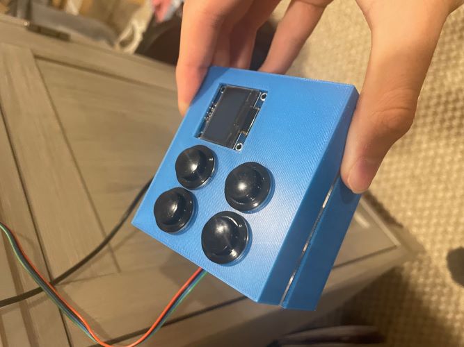
My final project will be a simple 3D printed box that houses everything inside execpt the DHT20 sensor. The box will have 5 holes in the top, 1 for the OLED and the rest for the momentary switches. Inside the box will also be a small strip of Neopixels for fun and to let the light be move visible I will include a small layer of clear acrylic. Using a Raspberry Pi Pico W the 4 switches will flip between screens on the OLED. Each screen is supossed to substitute time on my phone with using my project. Two of the screens for the OLED will be calendars one for tests/projects that week and the other for big assignments coming up. The other two displays will be the date which I will know form the Pico’s enternal clock and reading of the DHT20 sensor. Together it should remove the need to view and phone in the morning and keep track of tests/projects/assignments. In a second version I would like for every piece to be accessible from a html server hosted by the Pico W that can flip between screens, update the two calendar displays, and chenge the color of the Neopixles.
How I did it
DHT20
Working in Serial
Using this code from github, the library from the same site and this datasheet I was able to get the sensor to display info in my serial monitor. I needed to look at the data sheet to double check the pin outs and I noticed they were a little diffrent on the github image, all I did was change the pin locations on the sensor so everything stayed the same on the pico. This is what my serial moniter looked like:
Displayed on OLED
To get the OLED working I started with the sample code below that I got from chatgpt. I did run into a few issues though. The main problem was the library ssd1306. I tried downloading the library from Thonny by going Tools>Manage Packages then searching the library and I downloaded the first one. When I ran the code I got an error about the library. I then tried downloading the Adafruit ssd1306
from machine import Pin, I2C
from ssd1306 import SSD1306_I2C

i2c=I2C(0,sda=Pin(0), scl=Pin(1), freq=400000)
oled = SSD1306_I2C(128, 64, i2c)

oled.text("WELCOME!", 0, 0)
oled.text("This is a text", 0, 16)
oled.text("GOOD BYE", 0, 32)
oled.show()
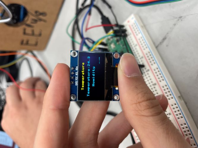
Then I worked on getting it connected to the DHT20. I then mixed the OLED code and DHT20 code with help from Chatgpt and got this working code that displays temperature then humidity. You can see what the OLED looks like here and what the code looked like for this.
import machine
import utime
from dht20 import DHT20
from ssd1306 import SSD1306_I2C

# I2C for DHT20 sensor
i2c1_sda = machine.Pin(2)
i2c1_scl = machine.Pin(3)
i2c1 = machine.I2C(1, sda=i2c1_sda, scl=i2c1_scl)

# DHT20 sensor setup
dht20 = DHT20(0x38, i2c1)

# I2C for SSD1306 OLED display
i2c = machine.I2C(0, sda=machine.Pin(0), scl=machine.Pin(1), freq=400000)
oled = SSD1306_I2C(128, 64, i2c)

while True:
    # Read temperature and humidity from DHT20 sensor
    measurements = dht20.measurements
    temperature = measurements['t']
    humidity = measurements['rh']

    # Clear OLED display
    oled.fill(0)

    # Display temperature and humidity on OLED
    oled.text("Temperature:{:.1f} C".format(temperature), 0, 16)
    oled.text("Humidity: {:.1f}%RH".format(humidity), 0, 48)
    oled.text("Temperature", 20, 0)
    oled.text("Humidity", 32, 32)

    # Show OLED display
    oled.show()

    # Delay for 1 second
    utime.sleep(1)
Date on OLED
For one of the screens on the calendar that I had I wanted to have the date on the OLED. To start I researched the best way to do use the date and time. I desided to use the Pi Pico’s Real-Time-Clock. I understand that the RTC might drift. I asked chatgpt to create a code that accessed the rtc of the pico and got it to print in the serial monitor.
import machine
import utime

# Function to get current date and time
def getDateTime():
    rtc = machine.RTC()
    datetime = rtc.datetime()

    year = datetime[0]
    month = datetime[1]
    day = datetime[2]
    hour = datetime[4]
    minute = datetime[5]
    second = datetime[6]

    return year, month, day, hour, minute, second

# Set the current date and time (Optional)
rtc = machine.RTC()
rtc.datetime((2023, 6, 6, 0, 0, 0, 0, 0))

while True:
    # Get the current date and time
    year, month, day, hour, minute, second = getDateTime()

    # Print the date and time
    print("Date: {}-{}-{}".format(year, month, day))
    print("Time: {}:{}:{}".format(hour, minute, second))

    utime.sleep(1)  # Wait for 1 second
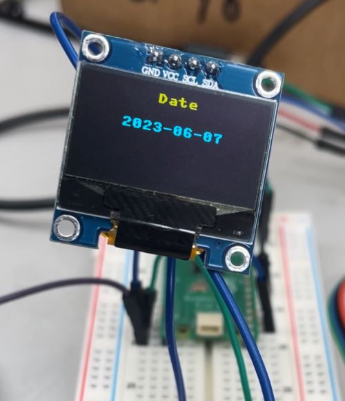
Once that worked I tried mixing it with the OLED code. I also wanted to remove the time of day part of the rtc. This is the code I came up with.
import machine
from ssd1306 import SSD1306_I2C
import utime

WIDTH = 128
HEIGHT = 64

i2c = machine.I2C(0, sda=machine.Pin(0), scl=machine.Pin(1), freq=400000)
oled = SSD1306_I2C(WIDTH, HEIGHT, i2c)

# Function to get current date
def getDate():
    rtc = machine.RTC()
    datetime = rtc.datetime()

    year = datetime[0]
    month = datetime[1]
    day = datetime[2]

    return year, month, day

# Set the current date (Optional)
rtc = machine.RTC()
rtc.datetime((2023, 6, 6, 0, 0, 0, 0, 0))

while True:
    # Get the current date
    year, month, day = getDate()

    # Format the date string
    date_str = "{:04d}-{:02d}-{:02d}".format(year, month, day)

    # Clear the OLED display
    oled.fill(0)

    # Display the date on the OLED screen
    oled.text("Date", 0, 0)
    oled.text(date_str, 0, 20)
    oled.show()

    utime.sleep(1)  # Wait for 1 second
NeoPixels
NeoPixels were a bit of a last minute thing but I got help from Ms. Dhiman for the test code and you can see that here:
import machine
import neopixel

# Configure the NeoPixel LED strip
NUM_PIXELS = 9  # Number of NeoPixels in the strip
PIN = 28  # Pin number to which the data line is connected

np = neopixel.NeoPixel(machine.Pin(PIN), NUM_PIXELS)

# Set brightness (from 0 to 1)
BRIGHTNESS = 0.5

# Clear all pixels (turn them off)
np.fill((0, 0, 0))
np.write()

# Function to set a single color
def set_color(color):
    np.fill([int(c*BRIGHTNESS) for c in color])  # Adjust brightness
    np.write()

# Set a single color
color = (0, 0, 255)
set_color(color)
Buttons to Switch Screens
I asked chatgpt how to implement a button in micropython and after it gave me a code I then implemented that code with the Date and DHT20 screens and was able to switch between the two with this code:
import machine
import utime
from dht20 import DHT20
from ssd1306 import SSD1306_I2C

# I2C for DHT20 sensor
i2c1_sda = machine.Pin(2)
i2c1_scl = machine.Pin(3)
i2c1 = machine.I2C(1, sda=i2c1_sda, scl=i2c1_scl)

# DHT20 sensor setup
dht20 = DHT20(0x38, i2c1)

# I2C for SSD1306 OLED display
i2c = machine.I2C(0, sda=machine.Pin(0), scl=machine.Pin(1), freq=400000)
oled = SSD1306_I2C(128, 64, i2c)

# Button setup
button_pin1 = machine.Pin(6, machine.Pin.IN, machine.Pin.PULL_UP)
button_pin2 = machine.Pin(8, machine.Pin.IN, machine.Pin.PULL_UP)
prev_button_state1 = button_pin1.value()
prev_button_state2 = button_pin2.value()

# Variables to track display mode
display_mode = 0
max_display_modes = 2

def switch_display_mode1():
    global display_mode
    display_mode = 0

def switch_display_mode2():
    global display_mode
    display_mode = 1

while True:
    # Read temperature and humidity from DHT20 sensor
    measurements = dht20.measurements
    temperature = measurements['t']
    humidity = measurements['rh']

    # Clear OLED display
    oled.fill(0)

    # Display content based on current display mode
    if display_mode == 0:
        oled.text("{:.1f} C".format(temperature), 0, 16)
        oled.text("{:.1f}%RH".format(humidity), 0, 48)
        oled.text("Temperature:", 20, 0)
        oled.text("Humidity:", 32, 32)
    elif display_mode == 1:
        # Get the current date
        rtc = machine.RTC()
        datetime = rtc.datetime()

        year = datetime[0]
        month = datetime[1]
        day = datetime[2]

        # Format the date string
        date_str = "{:04d}-{:02d}-{:02d}".format(year, month, day)

        oled.text("Date", 50, 0)
        oled.text(date_str, 25, 20)

    # Show OLED display
    oled.show()

    # Check button states and switch display mode if pressed
    button_state1 = button_pin1.value()
    if button_state1 != prev_button_state1 and button_state1 == 1:
        switch_display_mode1()
    prev_button_state1 = button_state1

    button_state2 = button_pin2.value()
    if button_state2 != prev_button_state2 and button_state2 == 1:
        switch_display_mode2()
    prev_button_state2 = button_state2

    # Delay for 1 second
    utime.sleep(.3)
Final Code
After some reasearch I learned that for now I would have to stick with changing the events in the calendar by editing the code and once I figuered that out I added two more buttons to the code and this was my final code:
import machine
import utime
from dht20 import DHT20
from ssd1306 import SSD1306_I2C
import neopixel

NUM_PIXELS = 9
PIN = 28

np = neopixel.NeoPixel(machine.Pin(PIN), NUM_PIXELS)

BRIGHTNESS = 0.5

np.fill((0, 0, 0))
np.write()

def set_color(color):
    np.fill([int(c*BRIGHTNESS) for c in color])
    np.write()

color = (0, 0, 255)
set_color(color)

# I2C for DHT20 sensor
i2c1_sda = machine.Pin(2)
i2c1_scl = machine.Pin(3)
i2c1 = machine.I2C(1, sda=i2c1_sda, scl=i2c1_scl)

# DHT20 sensor setup
dht20 = DHT20(0x38, i2c1)

# I2C for SSD1306 OLED display
i2c = machine.I2C(0, sda=machine.Pin(0), scl=machine.Pin(1), freq=400000)
oled = SSD1306_I2C(128, 64, i2c)

# Button setup
button_pin1 = machine.Pin(6, machine.Pin.IN, machine.Pin.PULL_UP)
button_pin2 = machine.Pin(8, machine.Pin.IN, machine.Pin.PULL_UP)
button_pin3 = machine.Pin(10, machine.Pin.IN, machine.Pin.PULL_UP)
button_pin4 = machine.Pin(12, machine.Pin.IN, machine.Pin.PULL_UP)
prev_button_state1 = button_pin1.value()
prev_button_state2 = button_pin2.value()
prev_button_state3 = button_pin3.value()
prev_button_state4 = button_pin4.value()

# Variables to track display mode
display_mode = 0
max_display_modes = 4

def switch_display_mode1():
    global display_mode
    display_mode = 0

def switch_display_mode2():
    global display_mode
    display_mode = 1

def switch_display_mode3():
    global display_mode
    display_mode = 2

def switch_display_mode4():
    global display_mode
    display_mode = 3

def celsius_to_fahrenheit(celsius):
    return (celsius * 9/5) + 32

while True:
    # Read temperature and humidity from DHT20 sensor
    measurements = dht20.measurements
    temperature_celsius = measurements['t']
    temperature_fahrenheit = celsius_to_fahrenheit(temperature_celsius)
    humidity = measurements['rh']

    # Clear OLED display
    oled.fill(0)

    # Display content based on current display mode
    if display_mode == 0:
        oled.text("Temperature:", 0, 0)
        oled.text(f"{temperature_celsius} C", 0, 16)
        oled.text(f"{temperature_fahrenheit} F", 0, 32)
        oled.text(f"Humidity:{humidity} %RH", 0, 48)
        oled.text(f"{humidity} %RH", 0, 64)
    elif display_mode == 1:
        # Get the current date
        rtc = machine.RTC()
        datetime = rtc.datetime()

        year = datetime[0]
        month = datetime[1]
        day = datetime[2]

        # Format the date string
        date_str = "{:04d}-{:02d}-{:02d}".format(year, month, day)

        oled.text("Date", 0, 0)
        oled.text(date_str, 0, 20)
    elif display_mode == 2:
        oled.text("Fab Presentation", 0, 0)
        oled.text("6/14", 0, 16)
    elif display_mode == 3:
        oled.text("Local Doc 6/21 ", 0, 0)
        oled.text("Global Doc 6/28 ", 0, 16)

    # Show OLED display
    oled.show()

    # Check button states and switch display mode if pressed
    button_state1 = button_pin1.value()
    if button_state1 != prev_button_state1 and button_state1 == 1:
        switch_display_mode1()
    prev_button_state1 = button_state1

    button_state2 = button_pin2.value()
    if button_state2 != prev_button_state2 and button_state2 == 1:
        switch_display_mode2()
    prev_button_state2 = button_state2

    button_state3 = button_pin3.value()
    if button_state3 != prev_button_state3 and button_state3 == 1:
        switch_display_mode3()
    prev_button_state3 = button_state3

    button_state4 = button_pin4.value()
    if button_state4 != prev_button_state4 and button_state4 == 1:
        switch_display_mode4()
    prev_button_state4 = button_state4

    # Delay for 1 second
    utime.sleep(.3)
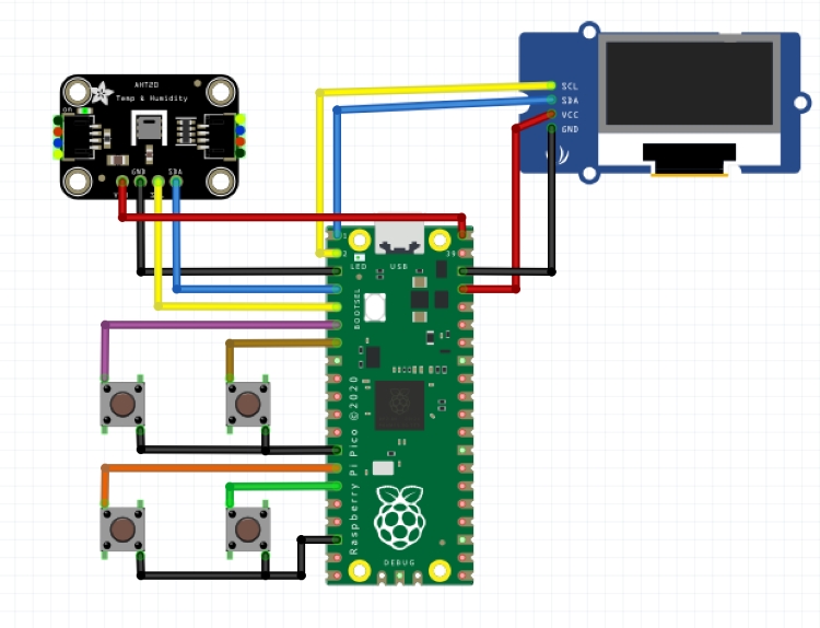
Final Schematic
In the schematic you can see seven components. Four of them are buttons. One of them is an OLED display. One of them is a Raspberry Pi Pico and the last one is in AHT20 Adafruit temperature in the humidity sensor. In my circuit, I will be using a DFRobot DHT20 sensor, I just couldn’t find a fritzing library for the DHT20, and my OLED screen does not have a breakout board; however, for functionality purposes, all pins would be the same in the schematic. The blue wires are SDA and the yellow ones are SCL, red is for power whether it’s 3 V or 5 V, black is ground and then each button is connected to ground and its own GPIO pin.
Board Production
KiCad
Making this board was simple, the only footprints I used was the raspberry pi pico and then I usind 4 pin headers multiple times. You can see that here:
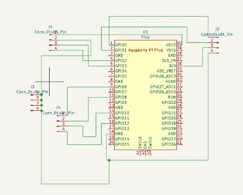
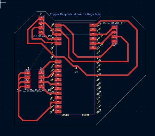
To make the PCB board I edited the footprint of the pico and removed some of the pads so that I could wire traces underneath them. I then moved the DHT20 header to the top left, the OLED header to the top right, and the momentary switches to the bottom left. You can see all of the here:
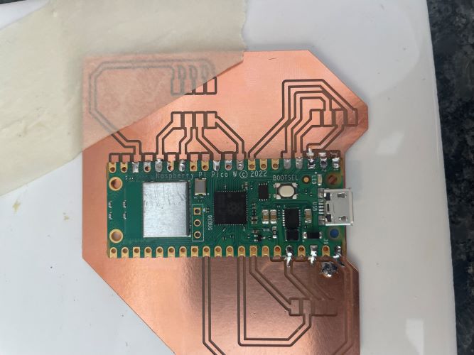
Milling
I used an OtherMill mill and I milled with a 1/64” end mill and a .0005 pcb engraving bit.
Here is what the board looked like after being milled:
![]()
Soldering
Since I removed some of the pads for the Pico on the board I would have to make sure the pads didnt connect to the board so put tape on the bottom of the Pico everywhere there was a chance of having continuity between the Pico and the board. I then started by soldering the Pico W:
Then I soldered on the headers and the soldering was done:

Case
For the case I wanted everything to be able to fit inside of it
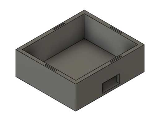
Bottom
Making the bottom was simple using calipers I measured how big my board was the create a simple rectangle that size then made one slightly biger by about .15in the extruded that up by 1in. I then used the mirror and diamention tool to create 4 holes that would help hold all 3 layers together. I then created two holes around where the pico usb cable would go and the DHT20 cable would go. Here is what the final bottom looks like:
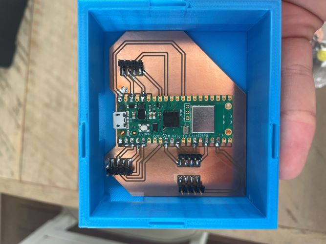
The board fit in the case perfectly:
Middle
The middle also was not hard to make. I Extruded the wall of the case by .1 and extruded it as a new body. Then to make it a flat plane I extruded one side to the other by selected to object in the extrude menu. I then created 4 circular holes at .61in diameter and then a small fifth hole for the OLED’s headers this is what it looked like at the end:
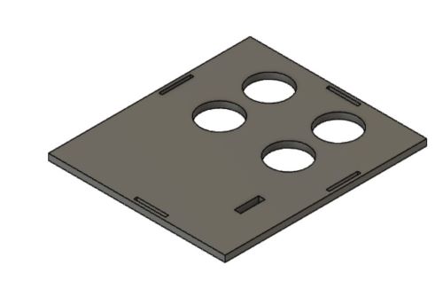
This one was flat because I would be laser cutting it by exporting the drawling of the body as a pdf. You can see the cut here:
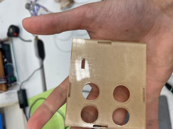
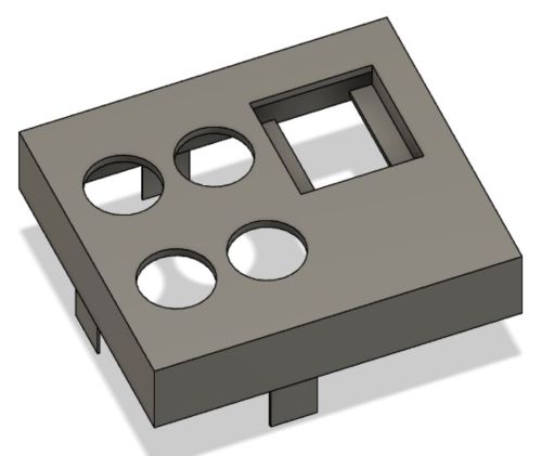
Top
I then created the top layer. To start I created an offset plane by .5in then created a rectangle the same size as the case. I then used an old sketch in Fusion to extrude the outer wall to the offset rectangle. I then recreated the holes for the button then created a bigger hole for the OLED display. Then I printed it:
Materials
Bill of Materials
| Amount | Material | Price |
|---|---|---|
| 1 | OLED | $6.99 |
| 1 | DHT20 Temp/Humidity Sensor | $8.60 |
| 1 | Raspberry Pi Pico W | $13.00 |
Materials Used and Where the came from
I also used PLA, clear acrylic, and momentary buttons. All of these came form the lab and I don’t know what it cost.
Others thats been done beforehand?
DHT20 working in micropython link
Neopixel working in micropython MS.Dhiman link
What did you design?
I designed the board I use in my final project using Kicad. I designed the box everything fits in using Fusion 360.
What parts and systems were made?
I made the box everything fits in. I also made the code that I will use by making my own code and mixing code linked above and code from Chatgpt to make my final code. I will also be creating simpler version of the final code to test steps on the way.
What questions were answered?
All of my question were answered. Every question that poped up I was able to figure out myself or from help in my lab and and if needed chatgpt.
What worked? What didn’t?
Everything worked the way I wanted it to exept one thing. Originally I wanted to recieve data form a digital calendar like a google calendar but I was unable to figure out a way to do that so for now I have to update the code to add or remove an event. The reason it doesnt work is because everyproject I saw just hosted the whole google calendar page on a large screen with a normal rapsberry pi, no projects with a pico or OLED dispay, also since they just hosted the whole page the didn’t barrow data form a spesific day or week which was my goal. I asked chatgpt and it told me a way to just host the google site the same way as the tutorials which was not helpful.
How was it evaluated?
It was evaluated the way I wanted it to. As a 4 button switching device that switchs between 4 diffrent screens stated above, but also as a device that will keep people off of their phones as everyone moves to keeping everything on their phones.
What are the implications?
The implications are for keeping myself and anyone who makes my project off of their phones as much as possible.
Future
In the future I want to make a interface that changes events, allows you to switch between screens, and change the color of the neopixels.