4. Embedded Programing
This week I worked on coding an Arduino Uno using c++, a Raspberry Pi Pico using micro python and c++, and a 412ATtiny using c++ and bare metal programimng. And for group work I looked into the RP2040 chip and compared it to a few others. This week my group was given the RP2040 and compared it to the other groups who got diffrent microcontroller. I helped with three spots on the spreedsheet and I helped Merritt with the Fip Bit test.
Arduino Uno
Getting an Arduino Uno to make a LED blink is pretty simple and its something I’ve done countless times in the Lab already. So I decided to make a traffic light blink using a Photo resistor.
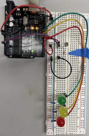
Arduino Circuit
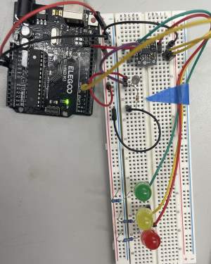
I set up the circuit so that the more light blocked out the more LED’s lit up. I used a Arduino Uno, a Breadboard, Male-To-Male jumper wires, three LED’s (1 red, 1 yellow,1 green), 10k ohm resistor, a 330 ohm resistor for each of the LED’s, and a Photoresistor. I connected the 5volt pin to the positive rail on the breadboard and a ground pin to the negative rail an the breadboard. This is what the circuit looks like:
Arduino Code
I used the Arduino IDE to program the Arduino Uno with c++. Here is my code. The pins might be wrong because I used the same code throughout this week but I adjusted the pins to fit the pins of either the Arduino Uno, Raspberry Pi Pico, or the 412ATtiny. The code works but taking in the Photoresistor as an input and converting it into a variable, and then using if else statments determins if the LED’s should turn on. The more light avalible the less LED’s and the more light you block out the more LED’s turn on starting with the green one.
// C++ code
//
void setup()
{
  pinMode(1, OUTPUT);
  pinMode(4, OUTPUT);
  pinMode(3, OUTPUT);
  pinMode(2, INPUT);
  Serial.begin(9600);
}

void loop()
{
  int LDR = analogRead(2);

  Serial.println(LDR);

  if (LDR < 800){
    digitalWrite(1, HIGH);
  } else {
    digitalWrite(1, LOW);
  }
   if (LDR <700) {
    digitalWrite(3, HIGH);
  } else {
    digitalWrite(3, LOW);
  }
   if (LDR <600) {
    digitalWrite(4, HIGH);
  } else {
    digitalWrite(4, LOW);
  }
}
Arduino Working
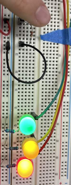
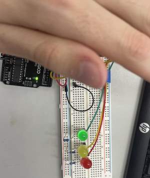
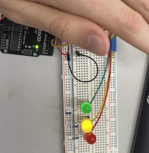
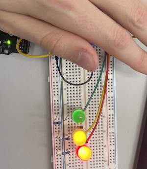
Here you can see me covering the photoresistor fully and all the LED’s are lighting up.
Raspberry Pi Pico
Using the Pico I coded the RP2040 microcontroller using c++ and micropyhton.
Raspberry Pi Pico Drivers
For a while when I plugged in my Raspberry Pi Pico it didn’t show up as a avalible port. I then oppened my object manager and saw that the Pico showed up as an unknown object. I googled it and I was told I needed to install the drivers for the Raspberry Pi Pico(I lost the link to the source). I installed the drivers from this link. I then was able to upload my code to my Raspberry Pi Pico.
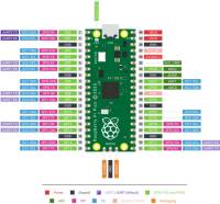
Raspberry Pi Pico Pinouts
These are the Pico’s Pinouts. The GPIO pins are what you use for the coding in the Arduino IDE and on Thonny.
Micropython
I decided to code an LCD screen with the Pico coded with Micropython through Thonny.
Creating the Working LCD
Before this week I had never used a LCD screen before. I googled it for help and found this link. I used this link as a tutorial to help me understand it.
Circuit
This what my circuit looks like:
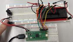
I used 2 breadboards, one Rasberry Pi Pico, one LCD screen(no I2C), 1 10k potentiometer, and some jumper wires.
Using the LCD pinouts I got from Sparkfun(My LCD is also Sparkfun):
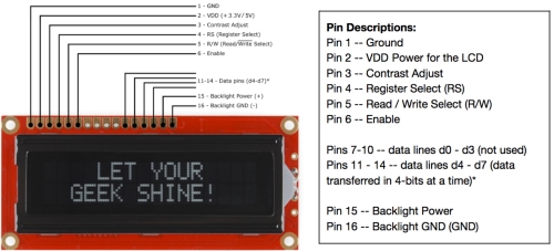
I was able to understand what was happening. Obviously gnd to gnd, and 5V to 5V. Then the contrast adjust its determines overall how bright the screen is but also if theres a background behind the letters, which was connected to the 10k potentiometer which you can see on the left side of the circuit. And then I don’t fully understand the purpose of the rest of the pins on the left side of the screen but the ones on the right side are all just data pins.
Coding LCD
Thonny
I downloaded Thonny on to my computor to code in Micropyhton. To connect my Raspberry Pi Pico I went into Thonnys settings and changed the Interpreter by going Tools > Options and click on the Interpreter tab. It oppened a drop down and I selected MicroPython(Raspberry Pi Pico). What I found was interesting that I acceditaly found out because I forgot to put into bootloader mode was I didn’t have to put the Pico into bootloader mode.
Code
From the website above I got a base code that I edited to:
from machine import Pin
from gpio_lcd import GpioLcd

# Create the LCD object
lcd = GpioLcd(rs_pin=Pin(16),
              enable_pin=Pin(17),
              d4_pin=Pin(18),
              d5_pin=Pin(19),
              d6_pin=Pin(20),
              d7_pin=Pin(21),
              num_lines=2, num_columns=16)

lcd.putstr('Jed Smith .')

lcd.putstr('Latin Fab Lab')
You can see in the code I mention 2 libraries. I will talk about them next.
libraries
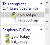
The two libraries I mentioned above you can download here, and I got them off of the site I linked above. Once I downloaded them I was a little confused on how to use them, I asked google and I found this website. I leared that I needed to open files and upload the libraries to the Raspberry Pi Pico. I clicked View>File, and was able to see all of the files on my Pico and my PC. I then found the libraries and clicked on them then clicked the 3 lines by “This Computer” and I was able to upload them to the Pico.
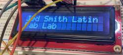
Pico Working
Heres what it looks like putting it all together. The diffrence between the the two photos is the potentiometer and how its turned, the clear letters are a few thousand ohms I don’t know the exact because the potentiometer doesn’t tell me and the bright backgorund is 0 ohms.
![]()
412ATtiny
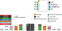
412ATtiny Pinouts
Here are the pinouts for the 412ATtiny. UPDI on the 412 is pin 6 and its also pin 6 on the Arduino, thats what you’ll use to connect the two. Remember, you don’t need to add anything to your code to make pin 6 and output on the Arduino, Jtagupdi(below) will do that for you.
Jtagudpi Library and Board Manager
To code the 412ATtiny you have to set the Arduino as a Boot Loader. To do that you have to install a library called jtagupdi and a board manager for the 412. I did this using this google doc. Once you add that library you have to up load an example code called jtagupdi directly to the Arduino. Then you have to change the selected board to the 412ATtiny and then you can send code to the 412ATtiny.
412 Circuit
I build the circuit the same was the the Arduino but I connected the Arduino and 412 using bit 6 on both of them. This is what that circuit looks like:
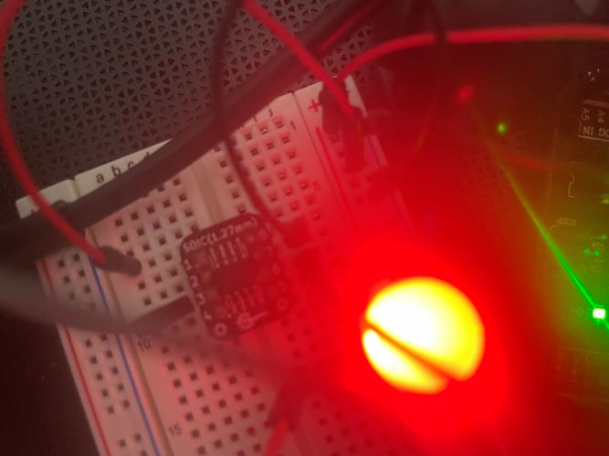
412 Working
Here you can see each LED turn on depending on the more I cover the Photoresistor.
Bare Metal Coding
Mr. Dubick gave us a lecture on what bare metal was and how to code it in C. Bare Metal is a way of coding that directly talks to the hardware of the microcontroller and bypasses extra tools that are implemented in the coding IDE’s. The registor in the 412ATTiny is PA or PortA on the pinout sheet so I would use that in my code. I used pin PA7 on the 412ATTiny and Ryan helped me understand how to acces that pin in demical coding so this is the code I finsihed with.
void setup()
    {
    PORTA.DIRSET = 128;
    }
void loop()
    {
  PORTA.OUTSET = 128;
  delay(1000);
  PORTA.OUTCLR = 128;
  delay(1000);
    }
What I learned
The main thing I learned this week was how to use Thonny and Micropython. I also learned how to use an LCD screen which I might use in my final project. I also learned about bare metal programming and I learned how to implement it on a 412attiny.