3. Computer controlled cutting
This week I worked on laser cutting and vinyl cutting. For my group work we worked on testing the dithering, kerf, and how making small setting changes affected the cut. I worked on dithering on cardbaord, wood, and acrilic, and I helped document for the dithering.
Laser Cutting
For laser cutting this week I worked on making a fully parametric push toy set and a workflow. And for the group work we tested diffrent settings for our Epilog cutter changing the DPI, speed and power. Me and my group also calculated the kerf, a portion of the material that burns away, of the laser cutter and the diffrent dithering settings on diffrent materials.
Parametric Push Toy Set
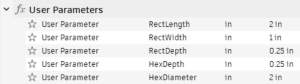
A parametric design is a design method where if you change the diametion of one aspect of the design, like a shape or line, the whole object will scale to fit that one line or shape. I desided to use Fusion 360 to create the set because I like the softwares parameters. In Fusion 360 I used constrianets and user parameters to make my designs parametric. You can see here some of the constraints I used and my user parameters:
Here is my file.
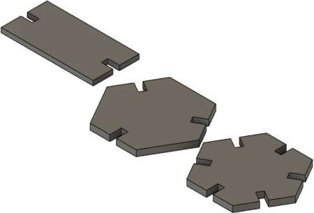
Rectangle Piece
The first thing I did was I changnged my document settings to inches. I then created a new sketch and created a rectangle that was 1in by 2in using the rectangle tool. I then added two consruction line to go across the rectagle to use as a mirror line. I then added two lines and mirrored them over both construction lines.
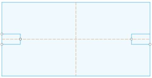
I then used the Trim tool to turn the rectangle into one smooth outline.
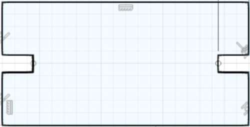
Thats the end of my rectangle piece.
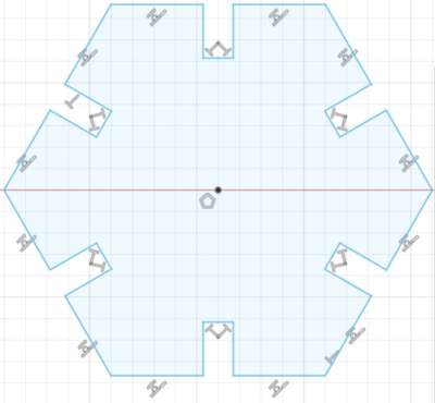
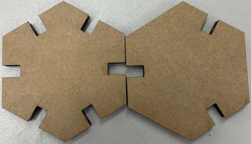
Hexagon Piece
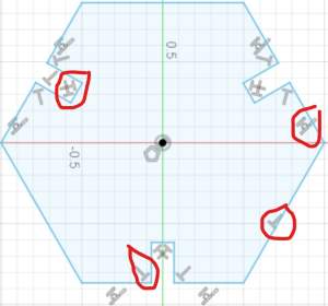
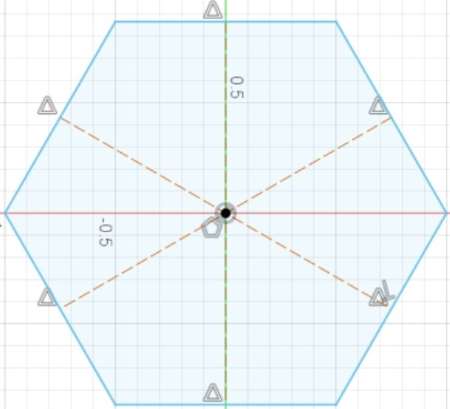
For my Hexagon I wanted to create one Heaxgon that had three holes and on that had six holes. The first thing I did was I created a new sketch. I then used the Inscribed Polygon tool to create a Hexagon. I then created construction lines that crossed the center of the hexagon to create mirror lines:
I then created a L going into the Hexagon that would act as the Push Hole. I then mirrored it across the construction line to create the out line of the hole. I then mirrored the Push Hole using a diffrent construction line to move the Push Hole to the diffrent side of the Hexagon.
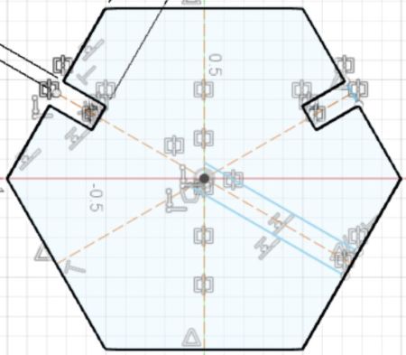
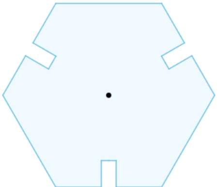
I then replicated it over three sides of the Hexagon and removed the construcion lines.
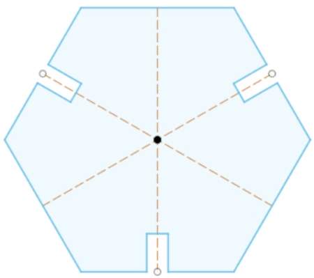
I then copied and pasted the Hexagon and created construction lines from angle to angle instead of side to side to move the Push Holes to all 6 sides:
Preparing my Pieces
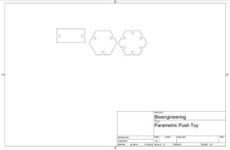
Since I made my pieces in Fusion 360 I needed to send them to Corel Draw where I could send the file directly to the printer. So I turned my file into a drawling, to do this I extruded my pieces so that they would show up on the drawling.
I set my drawling document settings to these:
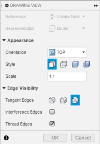
I then was able to export it as a PDF and open it in Corel Draw where I could sent it to my laser cutter to cut.
Laser Cutter
In our lab we cut with cardboard, wood, and acrillic, but there are many more materials you can use and you can see that on the Epilog Handbook here. To set the material up I opended the Laser Cutter and slide the cardboard into it.
I used the large epilogue laser cutter that we have in the lab, its the same one I used for my group work for this week. I Corel Draw I clicked file>print. That pulled up a little menu then I clicked print without changing anything. After I clicked print it opened Epilogue Software where I changed the settings for the print. In the Software there is a menu on the right there I made sure it was set to vector cut and imported the settings for cardboard cut. The large epilogue has a camera so I could see exactly where my cardboard was and I dragged my file over on top of it so that it would cut on it. Once all the settings were good I clicked print and sent it to the large epilogue. Then on the laser cutter I auto focused it, to do that you use the screen on the Epilog, you need to lower the bed enough so the laser is about the material then move the laser above the material then click autofocus. Before I seleced cut I turned on the air vents, in our lab its a light switch by the machine. Then on the Epilog screen I selected my parametric design as the job and then started cutting on the laser.
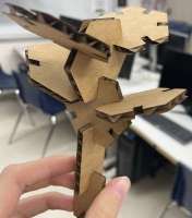
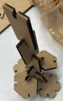
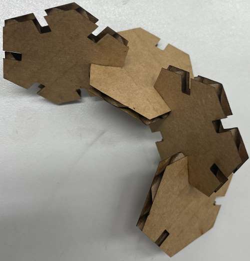
End Result
Vinyl Cutting
For Vinyl Cutting, I created a multi layered Pikachu sticker using Silhouette Studio.
Pikachu Sticker
Cutting Process
In Silhouette Studio there is a tab on the upper right side of the software called “Send”. Everytime I finished a trace I went to the “Send” tab and to send the Trace to be cut out on the Vinyl Cutter. In Silhouette Studio I made sure all the settings were set to what I needed before I clicked send and sent the file to the cutter. I made sure the material was set to “Vinyl, Glossy”, since that was the type of vinyl I was using. I also needed to set the knife depth to 1mm so that it didn’t start to cut into the cut mats. And finally I selected cut for the job. Thats everything I needed to do in Silhouette Studion but I was not done. With every diffrent cut I did, I had to prepare a cut mat. A cut man is the mat that you put your vinyl on, its a little siticky so it holds your vinyl in place. Everytime you put vinyl on a cut mat you should use a scrapper to make sure your vinyl is flat and stuck to the cut mat. Next I lined the cut mat up with my vinyl cutter and selected “load mat” on the machine. The machine then pulled the cut mat in and locked it in place. Once I did that I clicked sent in Silhouette Studio, then after the cutter was finished I clicked “unload mat” on the machine and I was done with that layer of my sitcker.
Pikachu Design Process
The first thing I did was I found a image of Pikachu I liked. I went with this one:

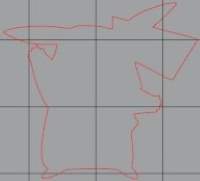
After I found that image I copied and pasted it into Silouette Studio, the software I’d be using for my sticker. I then used the Trace Tool and selected Outline Trace and traced the image. This is what the outline trace looked like:
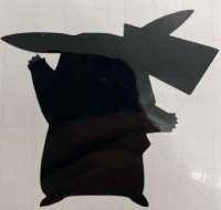
I used that outline and cut with black vinyl to create the outline of the Pikachu. This is what the outline looked like and what it looked like after weeding, the process of removing any vinyl that I didn’t want:
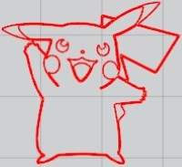
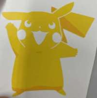
I then went back to the original image and did a normal Trace. This traced every line in the image allowing me to cut the yellow body for Pikachu. This is what that trace looked like:
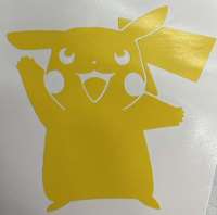
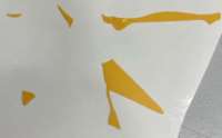
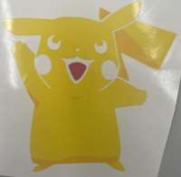
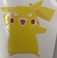
And this is what it looked like after I cut it on the yellow vinyl and weeded it:
I then went back to the original image of Pikachu and in the Trace Tool I selected Trace By Color this time. After selecting that I was able to use a color dropper to select the color I wanted traced. I used the Trace By Color tool for ever part of Pikachu, so the eyes, mouth, checks, and the shadows. Here is what each trace looked like cut and weeded:
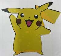
I then had to put each layer together. Here’s what it looked like:
Hornet’s Logo
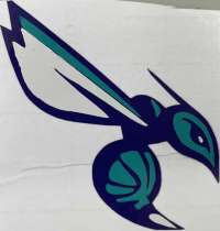
I wasn’t happy with the way my Pikachu sticker turned out so I decided to make a new one. This time I choose the Charlotte Hornet’s Logo:

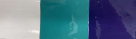
My whole process was the same with the Pikachu sticker. I started with gathering my vinyl:
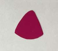
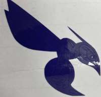
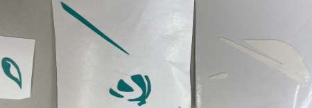
Then in Silhouette Studio I did an outline trace of the Hornet and I cut the outline of the Horner on purple vinyl and here is what it looked like weeded with an exacto knife:
Then I used the trace by color tool to trace the white and teal/blue of the logo. Then I cut them and weeded them. The first time I cut the head wasn’t fully cut through so I run it again and changed the knife depth and that worked.
I then used an exacto knife to carefully place layers on top of the base and this is what I finished with.
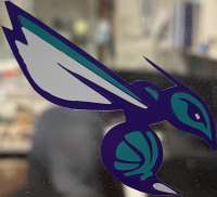
This is what it looks like on the window in the lab.
What I learned
This week I learned how to create a multilayered sticker but also different tools inside Silhouette studio to help me make a multilayer sticker. I also learned the importance of implementing parametric features in my designs and I will definitely be using parametric designs in the future.