11. Input devices
This week I worked on defining my final project idea and started to getting used to the documentation process. Here is my group work.
Here are my files for the week.
For this week are used an accelerometer as an input and I use an RP 1240 to read that input. To start off on the week I read an article about I2C to help understand how I2C worked. After that I use the video that Dylan found and sent to us to work on using this Xiao, RP 2040. I used anbreadboard to get a reading from the accelerometer, after that, I went to create a board that I later milled and soldered. After that I got that board working with the accelerometer and I was getting readings.
Breadboard Test
Using this code from the Dylan’s video. Go here for the Github page. You want to download the “vector3d.py” and the “imu.py”, those are both on the GitHub page linked above.
Main Code
from imu import MPU6050
from time import sleep
from machine import Pin, I2C

i2c = I2C(1, sda=Pin(6), scl=Pin(7), freq=400000)
imu = MPU6050(i2c)
#imu.accel_range = 2

while True:
    ax=round(imu.accel.x,2)
    ay=round(imu.accel.y,2)
    az=round(imu.accel.z,2)
    gx=round(imu.gyro.x)
    gy=round(imu.gyro.y)
    gz=round(imu.gyro.z)
    tem=round(imu.temperature,2)
    print("ax",ax,"\t","ay",ay,"\t","az",az,"\t","gx",gx,"\t","gy",gy,"\t","gz",gz,"\t","Temperature",tem,"        ",end="\r")
    sleep(0.4)
I then used it on a breadboard and a Xiao and I got it working so I moved on to KiCad.
KiCad
For this board I wanted to make a simple I2C breakout board using 3.3v, becasue thats what the accelerometer required(I should of looked at the data sheet to see if I could use 5v but I didn’t think if that at the time).
Schematic
To start it off I imported the Xiao footprint, then a 4 pin header footprint and made a simple breakout board using SDA, SCL, 3v, and GND.
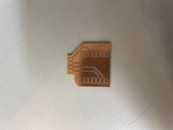
PCB Editor
I updated the PCB Editor to the Schematic then made the traces and outline.
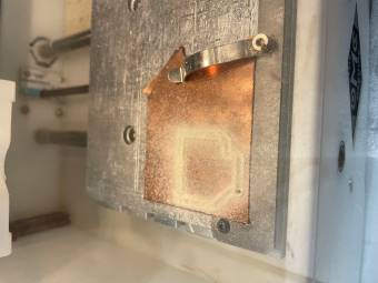
Milling
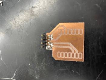
Using the Bantam and a 1/64” end mill I set up my file like I did in electonics week. And then started milling. This is what it looked like after I milled it:
Soldering
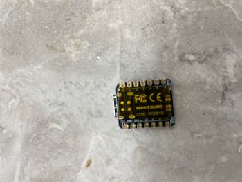
To Solder the Xiao Rp2040 you need to add heat resistance tape to the bottom so you don’t fry it.
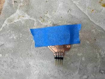
After that I started soldering.
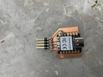
I taped the board down and soldered the male headers first. You can see that here:
I then soldered the Xiao. You can see that here:
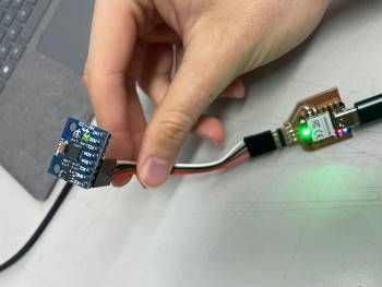
And I knew my board was working when the LED on the accelerometer turned on:
Working on my board
Once I knew my board worked I uploaded the code to the board and I was getting a reading in the serial moniter on Thonny. You can see that here: