8. Electronics Production
This week I worked on milling and soldering the board I made in week 06, for this week I will be working with my Kicad File. For group work I helped document and helped with the trace clearence.
Board 1
Kicad 1
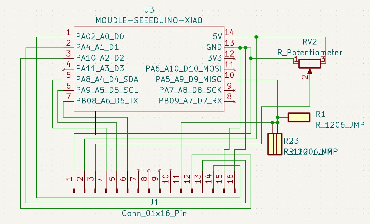
Throughout the process of milling my board I had to update and change my Schematic and PCB editor in Kicad. Firstly I noticed that for some reason pin 4 on the Xiao in the Schematic wouldn’t connect properly to wires, so in the PCB editor I wasn’t able to add a trace to it. Eventually I decided to use a diffrent pin. The sckematic looked like this:
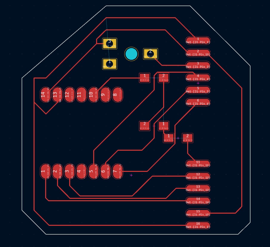
I then copied the schematic and put it on the PCB editor. I then spent some time just moving footprints around to make a board that would be easy solder and wouldn’t use to much pcb. This is what I finished with:
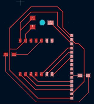
I then went to export the file.
Exporting the Board
To open the file in Bantam Tools I when to File>Plot then I selected Copper Cut and Edge Cut to be saved my cuts as a gbr file. You can see my plot setting here:
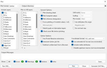
I then opened the file in Bantam Tools.
Milling Board 1
I milled using the new Bantam Software. In the initail setup I opened my file, I cleared all previous cuts and selected by copper layer for the top and my edge cut for the outline. I then seleced the bits I would you, I used a 1/32’ flat end mill bit and a .0005 engraving bit. I then but the peice of pcb into the mill, to make sure it stayed in place I put nito tape on the back of the pcb:
Then I needed to set the z offset, I used the Z-only Stock Probing to find the Z offset. If you do it this way you need to have your pcb in the bantam and you need to move the clip onto the pcb so that the machine can detect an electrical signal the second the bit reaches the pcb, I then got a thickness of 1.76 mm. I then set the plan offset for the x and y as 4mm. Then I was ready to mill. During the mill when I was changing bits the rubberband on the spindle snapped, I didn’t know what to do at first so I canceled the mill instead of stopping it and after I put a new rubber band. And I restarted the mill.
Soldering Board 1
This is what the board looked like deburred:
![]()
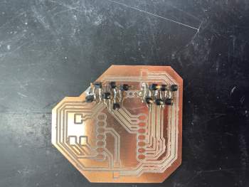
I started soldering the headers where I first found trouble. The pabs for the headers were to close together to solder the headers in a single strip. To get around this I tried solder each single header one at a time. This kind of worked but it looked horrible. You can see that here:
After doing that I soldered on the resistors on:
Then I went to solder on the seeed:
After this I used a multimeter and tested to make sure the I didn’t fry the Seeed. I found out that I had a few solder bridges by the headers which didn’t reallty surprise me and the Seeed wouldn’t turn on, it was also hard to plug in because I put a resistor infront of the port. Going in to making the new board I knew there were a lot of things I needed to change.
Board 2/Final
KiCad 2
The first thing I did was I rewired the whole board so that the Xiao’s port was easier to use. I then went into each pad properties in KiCad and moved each pad by 1.3 mm so that the distance between each pad would be the distance between the black part of the headers and not the actual headers. After doing all of that this is what the PCB editor looked like:
Milling Board 2
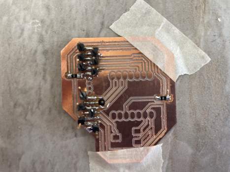
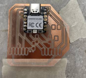
Using the same steps as above I milled this version of the board. This is what the board looks like:\
![]()
Soldering Board 2
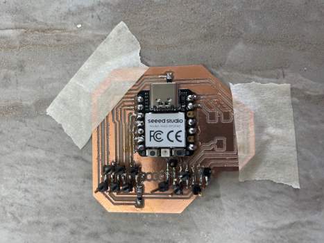
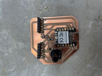
This time when I was soldering I soldered on the Seeed first, this way if I fried it I wouldn’t lose to much progress. This is what that looked like:
Then I soldered everything else on and tested with a multimeter to make sure everything worked. This is what I finished with:
Testing the Board
After soldering the board and tesing it with a multimeter and makeing sure th Seeed wasnt freid I tried using the code I used back in week 04.
from machine import Pin
from gpio_lcd import GpioLcd

# Create the LCD object
lcd = GpioLcd(rs_pin=Pin(16),
              enable_pin=Pin(17),
              d4_pin=Pin(18),
              d5_pin=Pin(19),
              d6_pin=Pin(20),
              d7_pin=Pin(21),
              num_lines=2, num_columns=16)

lcd.putstr('Jed Smith .')

lcd.putstr('Latin Fab Lab')
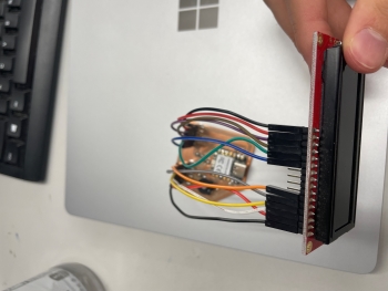
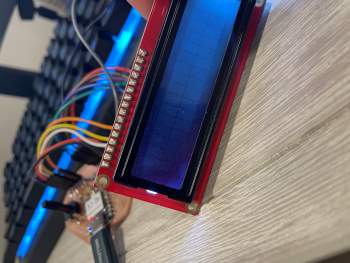
I don’t know if I made in error in downloading micropython to my Xiao or if something in the code didn’t translate to the Xiao properly for somereason but I couldn’t get the letters to appear on the LCD screen. But here is the board wired to a LCD screen and the background of the LCD screen turning on:
What I learned
This week I learned how to export my files from KiCad and how to use the new Other Mill/Bantam software. I like the new version of the software a lot more than the old one and I will use the new version in the future. I also learned who to fix the bantam spindle(Rubber Band).