10. Mechanical Design, Machine Design
This week I worked on a Lunch Duty Machine with my group mates. The goal of the machine was to use a squeegee to push food to one part of the table that then someone could clean up. It used stepper moters to raise and lower the squeegee, and stepper moters to move the machine forward. The machine also used LiDAR to stop itself from falling of the table. Here is the group site.
What I did
I worked with Ryan and Griffin to on the machanical side of the Machine and we worked on visual cad and putting everything together.
Crude CAD Design
To start off the week I created a very basic, and crude design on what the machine would look like in Fusion 360. While Ryan and Griffin created CAD Designs for the Squeegee mount and the Wheel system, I quickly created this rough outline so that everyone in the gorup can get a feel for what the machine would like and a better graps of what it would look like and to make sure we were all on the same page about the design.
Crude Design Process
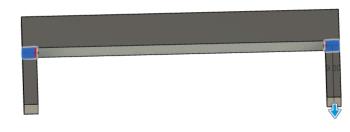
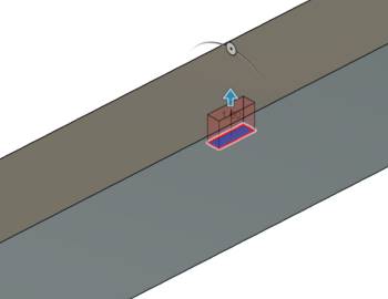
Here is the final design for the crude model. In the modle you can see that the sides are hollow to show how the stepper moders would be mounted, the design also has a thin hole through the middle we thought at one point we could use a long stepper to move the squegee up and down, there are also 2 slots with screw holes on the sides of the frame and those were gonna be a way we could mount the LiDAR sensors.
Fusion 360 Frame Design
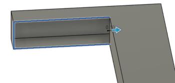
To start off for this design I created created a sketch then a rectangle using the Create Sketch Tool followed by the Rectangle Tool. For the size of the rectangle I eye balled it because we hadn’t gotten the size of the table and knowing this design wasn’t going to be final. I then extruded it by 5 in to give it a 3d form. Heres what that looks like:

I then created a sketch on the side of the rectangle and created two small squares that I would extrude to be the legs. This is what they looked like extruded:
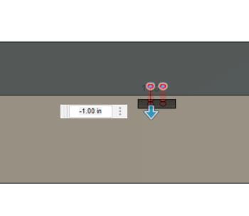
I then used the shell command on the inside of the legs to create a hollow shaft for the stepper moters to work in. Heres that:
I then thought of a way to mount the LiDAR sensors, which was to glue or tape the senosrs to boards that would then screw into the build. To do this I negativly extruded room for the boards then negativly extruded screw holes. Heres what those look like:
Then you can see it all together in the 3d modle above.
Prototyping
Cardboard Shaft Prototype
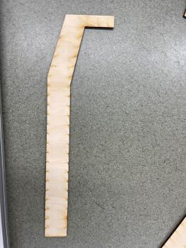
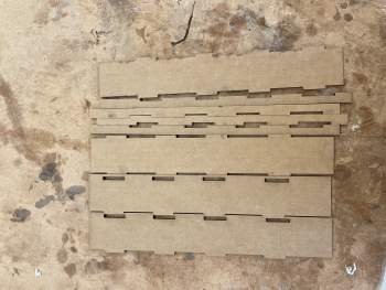
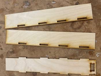
After I was done with my crude design, I worked with Ryan on how to connect the wheel machanism to the legs of the Machine. By this point we decided the squeegee would move up in down resting on a trapizod nut on long steppers that were housed in the legs of the machine. We decided on a system that hould house the long steppers in the same 3d print as the wheels and to create the shaft we made a tabbed shaft to laser cut. Ryan took the shaft from fusion and exported it as a pdf and sent it to me.
Once I loaded the cut onto the same Epilog Laser Cutter I used in week 03. I started with just a cardboard test cut to make sure we liked the way it looked and to make sure it would fit in Ryans 3d print. I imported the Cardbaord cut setting in the Epilog Software then I sent it to the Laser Cutter where I clicked print. This is how the cut turned out:
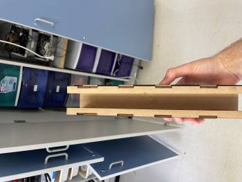
This is the cut hot glued together:
You might see that in the photo of the cardboard pieces cut there is a few extra, the pdf Ryan set me had practically one and a half pieces to create a shaft, so I just kept hold of the extras in case we needed them for any reason.
Wood Shaft
Wood Shaft Prototype
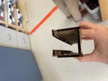
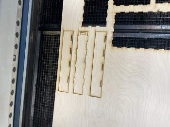
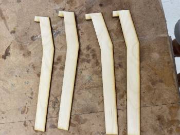
After putting on the cardboard, me and Ryan went back to design, and we removed the part that faced inwards then he sent me the PDF for the cut and I went to the laser cutter and cut it out on 1/8 inch wood to do this. I followed the same steps as for the cardboard except I set the settings to 1/8 inch wood cut after that since this wasn’t the final part I taped it together so that Ryan could get it quickly and he could use it in his design to test out the sizing, once we knew that fit.
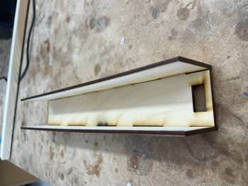
Wood Shaft Final
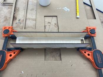
I went back cut it twice and then we used wood glue and clamps to hold it together after the wood. Glue is trying to give it back to Ryan and it fit in the parts perfectly.
This is what it looked like clammped:
T-bar Issues
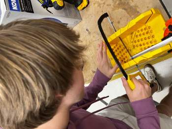
Then what I did was, I helped cut the T-bar. The problem was our original design included cutting the T-bar as well as cutting our guide rails. Here is a photo of me cutting the T-bar. I used clapps to hold the bar in place and used a hacksaw to cut it:
However the guide rails were hardened steel so we couldn’t cut through it. We tried a little bit and Dr. Taylor tried with a sawzall to do it but it didn’t get anywhere. Heres the jig we created for that:
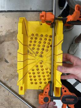
We then decided that instead of cutting the guard rails, we should just cut the T-bar so we went to the drill press and spit while they’re cutting the T-bar to fit the guide real as well as the 3-D print to fit the guard rails. Cutting the T-bar took way too long because the bit kept coming loose and the hole was it lined up perfectly wake up having to go back to remove a little bit and then test to see if it would fit and then realized I didn’t, and then go back and cut again, finally we got it. Then we brought it back over the rest of the machine and started our full assembly.
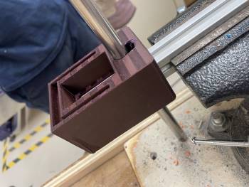
Here’s what it looks like after getting the gide rail through the t-bar and print:
Griffins Pieces
Griffin Dow
Griffin was in charge of the squeegee mount. The dow we had that connected to the squeegee was way to long so he asked me to help him. We decided the best plan was to use the Table saw. Using the sled that we had in the lab and clamps we created a jig that would hold the dow in place. You can see that here:
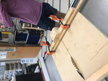
Then I turned on the saw, raised the blade and cut it.
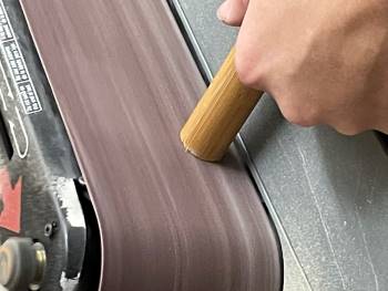
Then after that I sanded the edge down a little bit. You can see that here:
Griffin Board
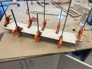
This Board that Griffin made a file for was what connected the squeegee prints to the stepper moters and the guide rails. To get the right thickness we used the laser cutter on 1/8th inch wood and we cut it 3 times then glued them all together using wood glue and clamps.
Machine Supports
Dr. Fagan looked over our machine before we were done and noticed that it would most likely tip over since it only made contact on the sides of the table. Ryan quickly made a file for me to laser cut and print a file that would connect it to the t-bar.
This cut was a little to small and it didn’t fit around Griffin’s board so I went back and resized parts of it and got it to fit: