4. Computer controlled cutting
Objectives:
Group assignment :
- Characterize your lasercutter’s focus, power, speed, rate, kerf, joint clearance and types
Individual assignment :
- Characterize your lasercutter’s focus, power, speed, rate, kerf, joint clearance and types
- design, lasercut, and document a parametric construction kit, accounting for the lasercutter kerf, wich can be assembled in multiple ways, and for extra credit include elements that aren’t flat
before you start
tips and tricks for setting up inkscape
Before setting options, I will explain the problem one can have when drawing and wanting precision in measurements
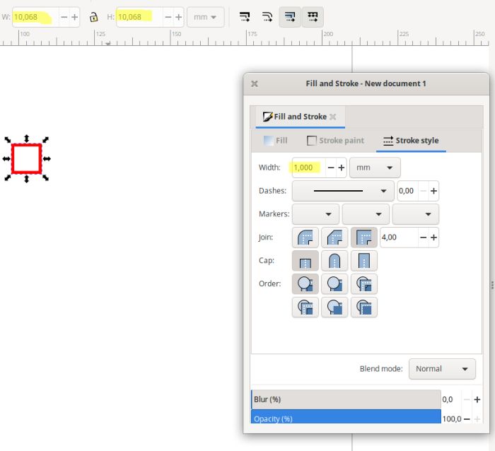
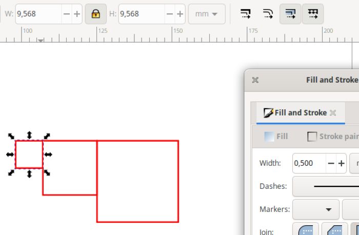
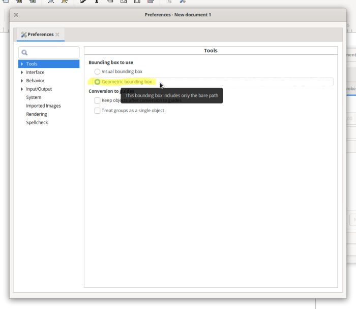
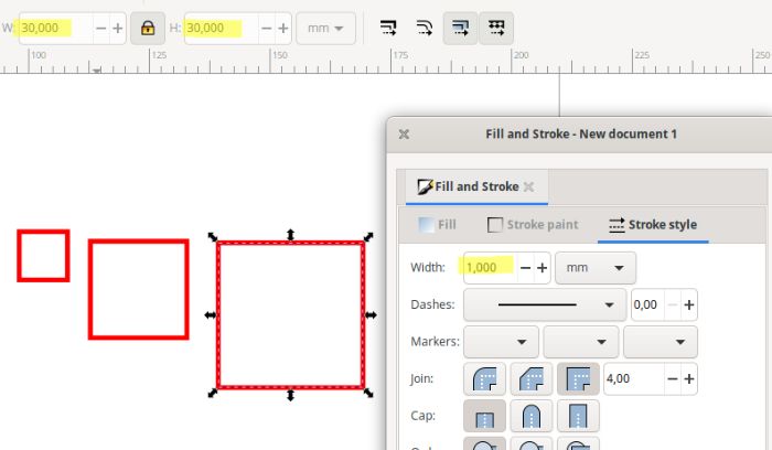
Let’s make a 10mm square and try to put an outline at 1mm
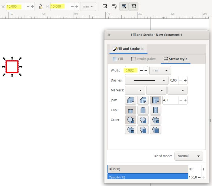
By changing the contour, the value of the square increases to 10.068mm. This is not a big change, but it is not an accurate one.
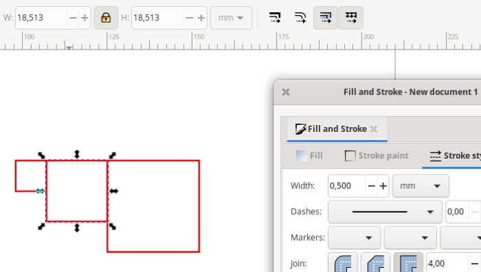
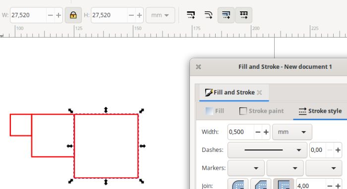
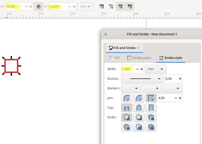
Duplicate the square and increase the dimensions to have a 20mm square and a 30mm square
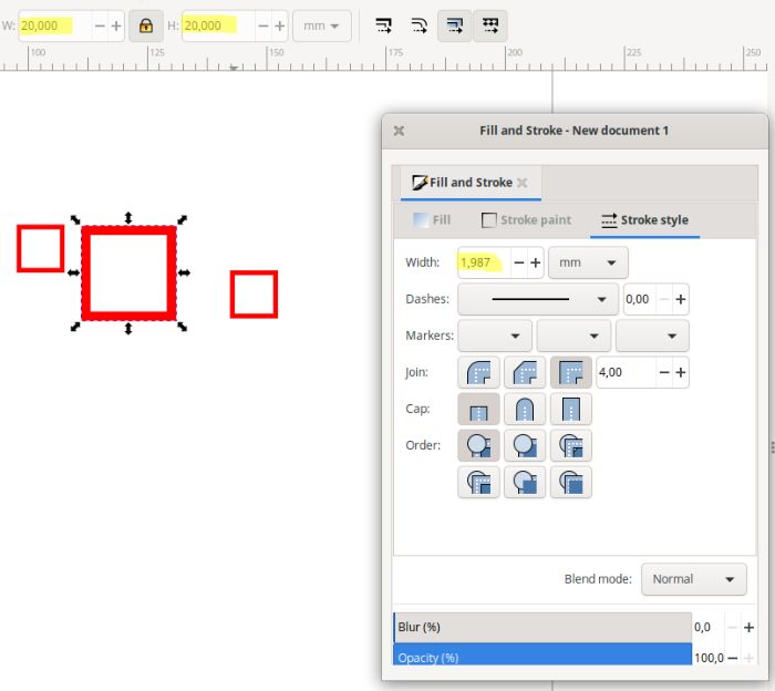
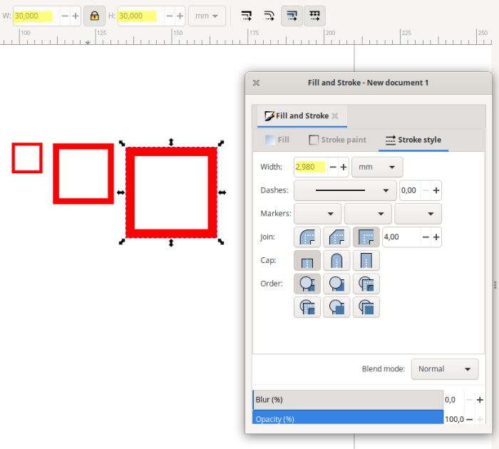
It is noticeable that the contour line increases. Not very pleasant in rendering, but that’s not the problem yet.
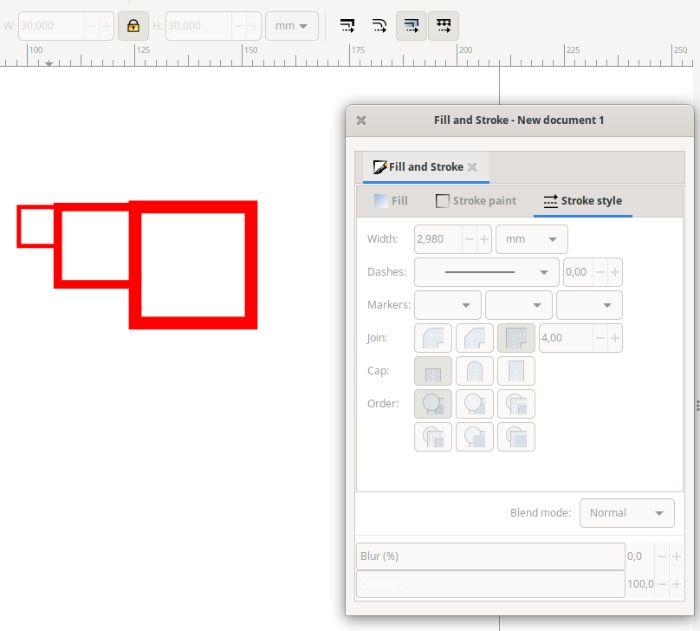
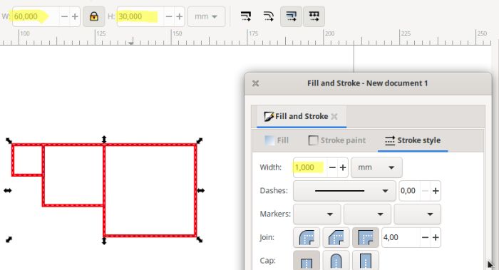
If we now select the whole and set the outline to 0.5mm, we notice that the total dimension is not equal to the “normal” value. We should have for the width 10+20+30mm, evening 60mm, but here we have 54,602mm (big problem here for the precision)
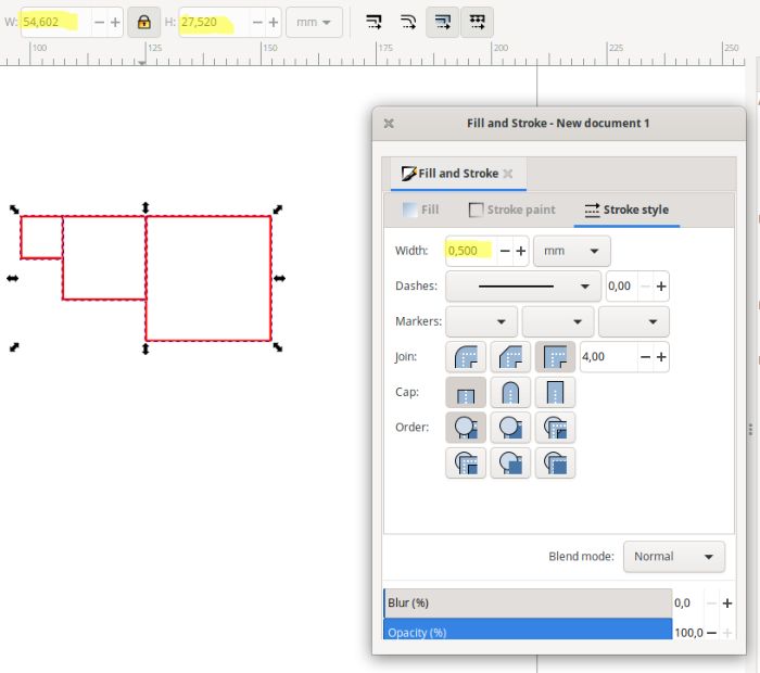
What can be done about it?
There are two changes to make in the inkscape preferences
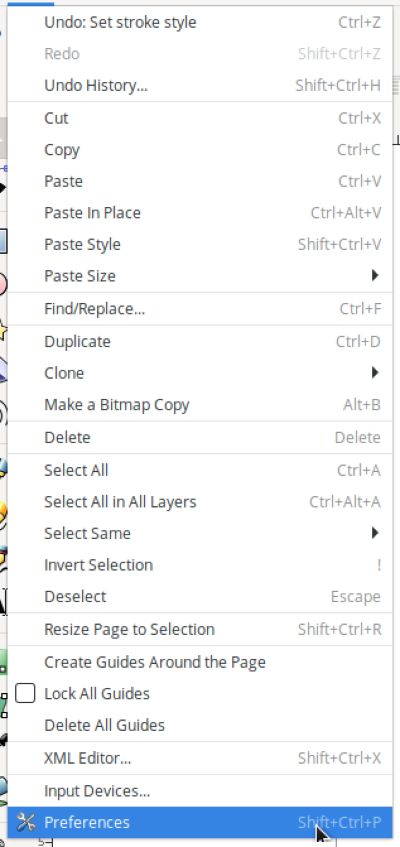
![]()
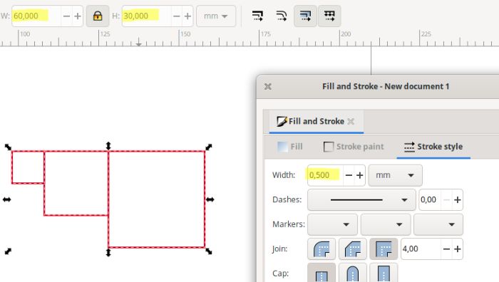
Here is the result by carrying out the same steps as before
There, now it’s correct. The size of the object is taken into account, not the object + outline
Group assignment
Link to ULB group : link
In the fablab, we work with two Gravograph 80 Watt CO² laser cutters (one of 610mmx610mm and one of 1220mmx610mm)
Lasercutting
Power and Speed
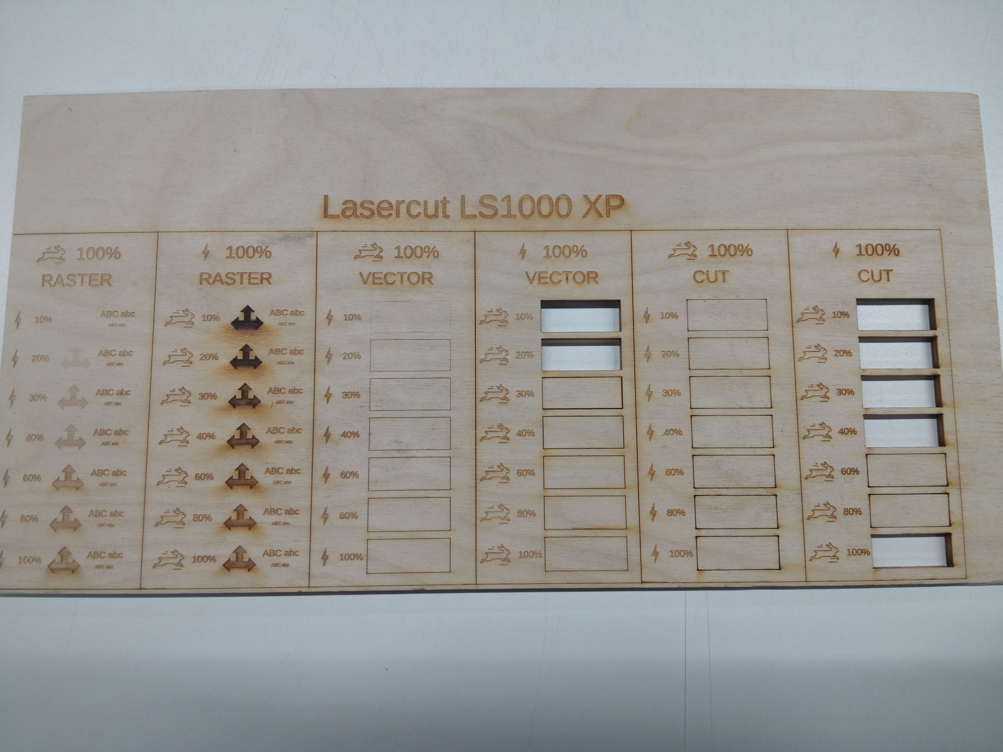
To determine the power and speed of the laser, here is a test jig that allows you to view different parameters.
Be careful, these parameters are valid only as an indication, it will be necessary to test before especially if the material is not the same.
 )
)
files :
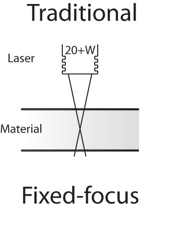
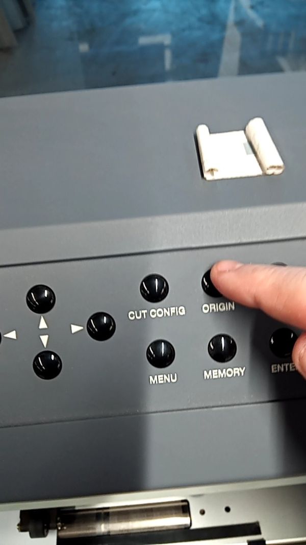
Focus
The focus setting is extremely important for laser cutting. It will determine the correct cutting of the material.
We do it manually. Here is a video showing the operation:
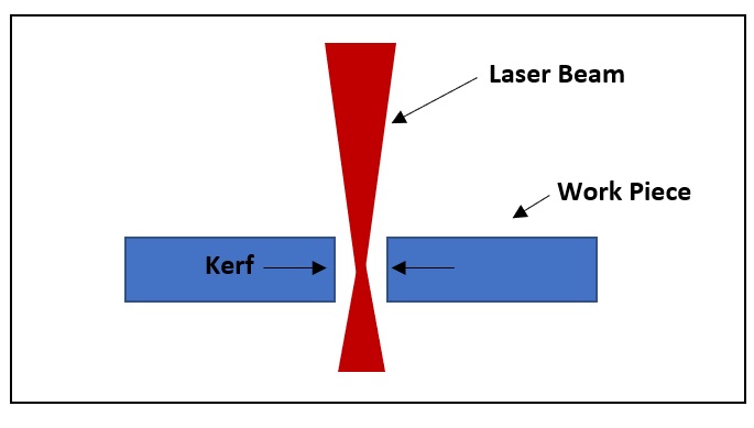
kerf
The kerf is also called “cutting width” or “laser line thickness”. It is a key parameter to consider when creating files for laser cutting (or any machine that cuts digitally or not).
When the laser beam of your machine removes material from the workpiece, the space created is the kerf.
What determines the width of the laser beam?
The elements that determine the laser’s kerf are
- Focal length (distance between the lens and the workpiece).
- Material thickness (the laser beam focuses before it dissipates. So the thicker your material, the wider the cut is likely to be on the underside. The kerf will therefore be greater)
- Type of material (its resistance to fire, burning. Plastics burn more quickly, so the kerf is higher)
- Type and pressure of the compressed air injected
- Straight or curved line
- Cutting speed (the slower the speed, the longer the laser stays on the part, so the more material is removed)
Why is it important to know the kerf thickness?
Why take the time to know the kerf width? :
- To make perfect interlocking joints : this is important for the fit. For example, for a notched box, you can create a model that assembles by force and does not require nails or screws. For other volumes, this allows sufficient support while the glue sets.
- Better anticipate the final result.
- Determine how much material you can leave when cutting. When you want to remove a lot of material to leave very fine lines, knowing this information is essential. Generally, it is said that it is better to leave as much width as thickness of material. In my experience, for Plexiglas the width corresponds to the thickness, for wood I recommend half the thickness.
Determine the kerf
To determine the kerf, here is a simple file that will cut out 10 tabs. Normally, the whole thing should be 10 cm

file : kerf test
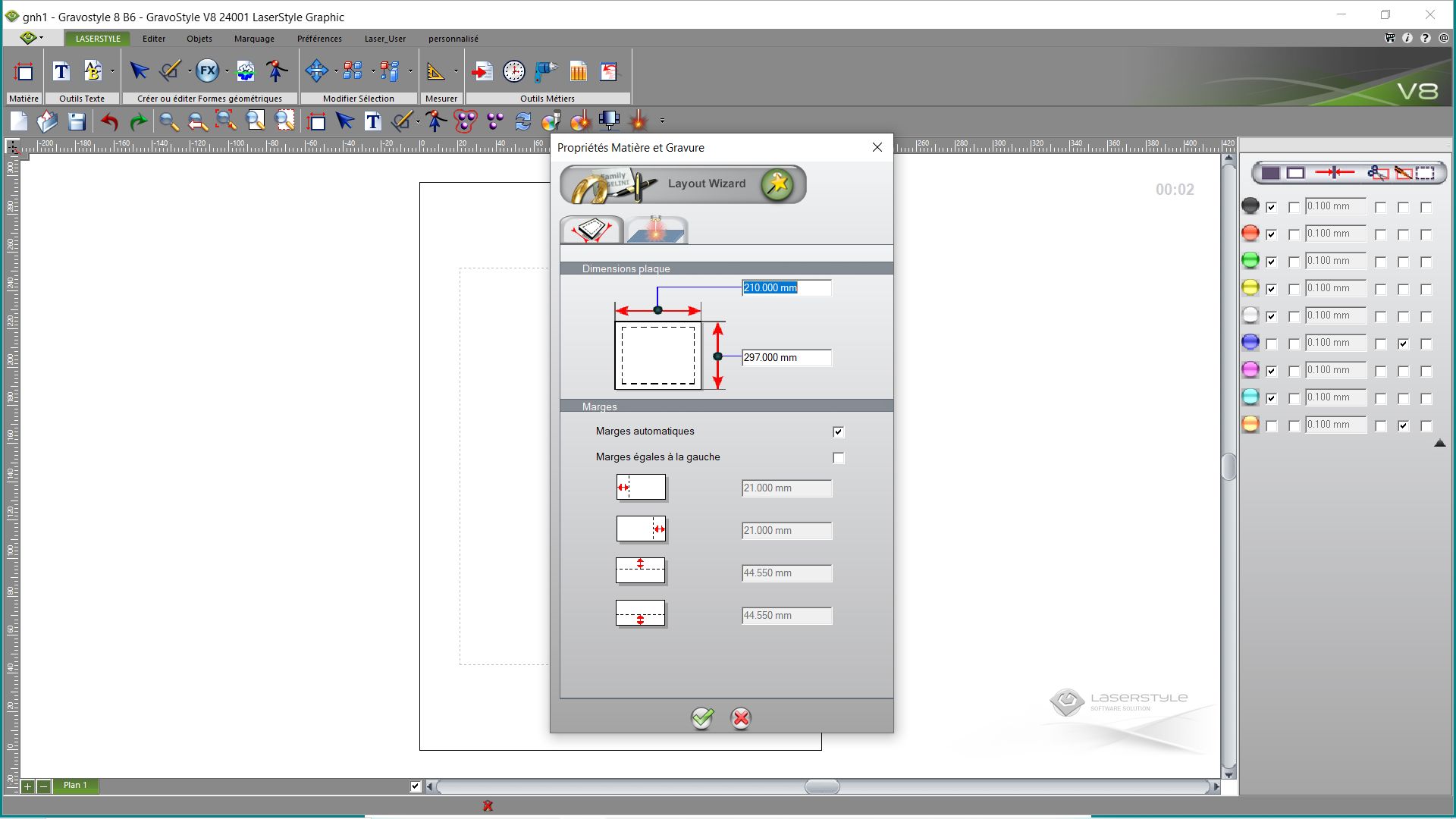
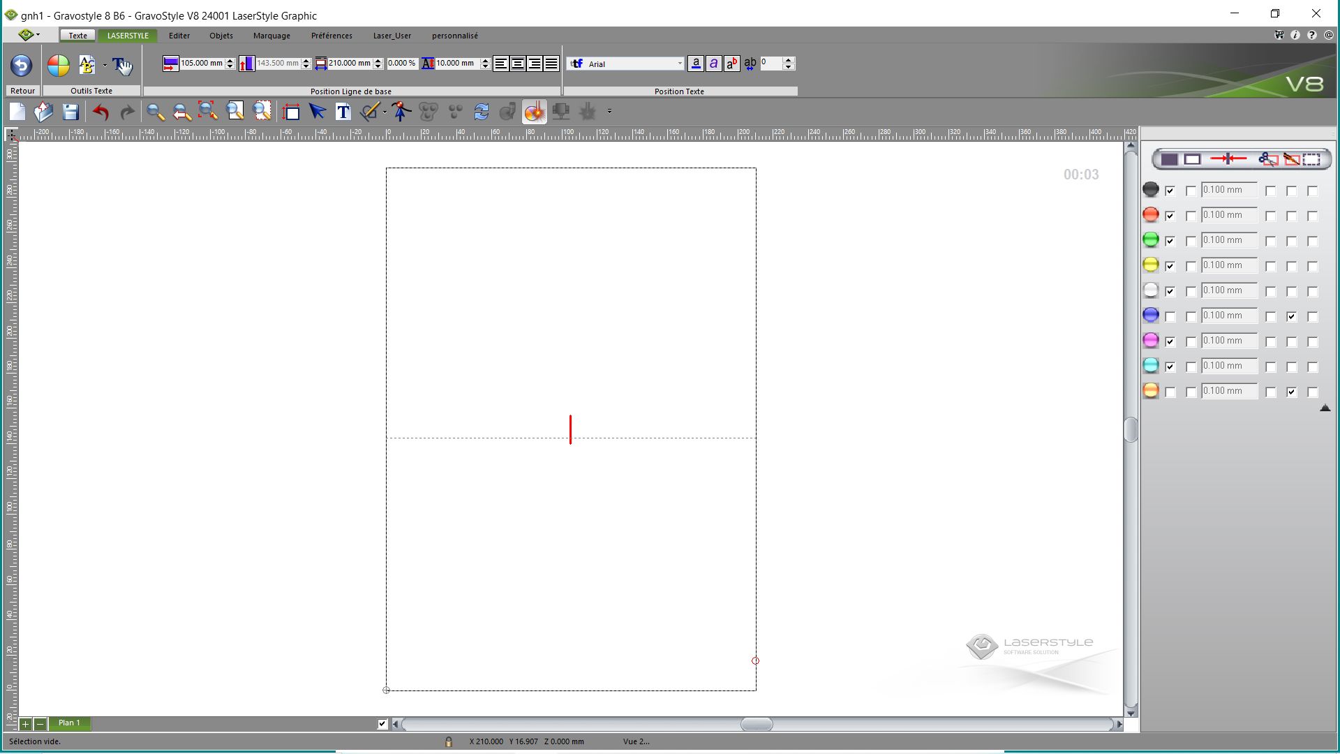
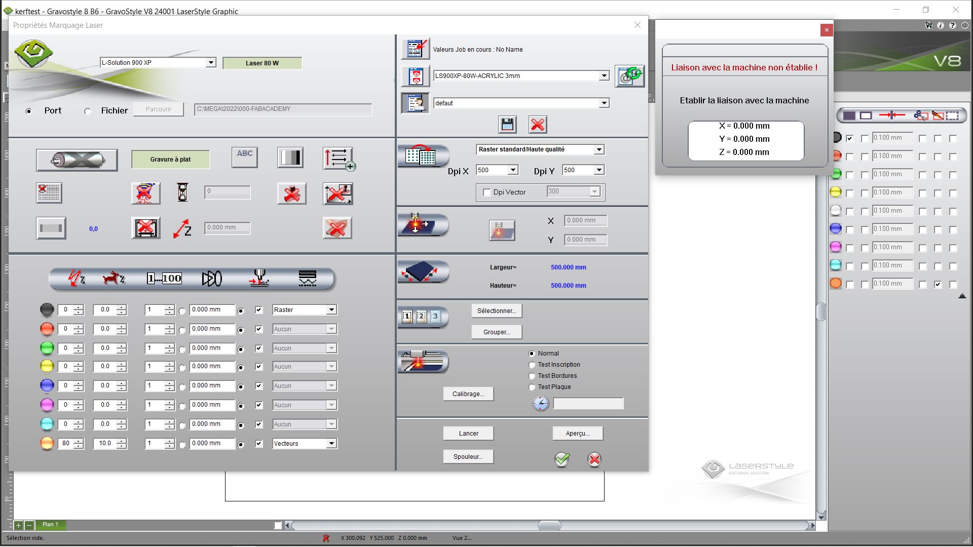
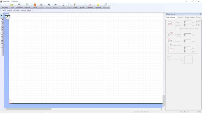
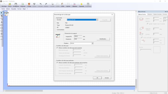
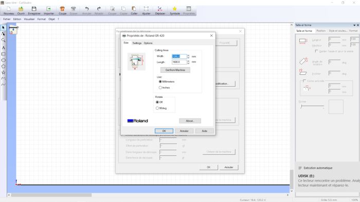
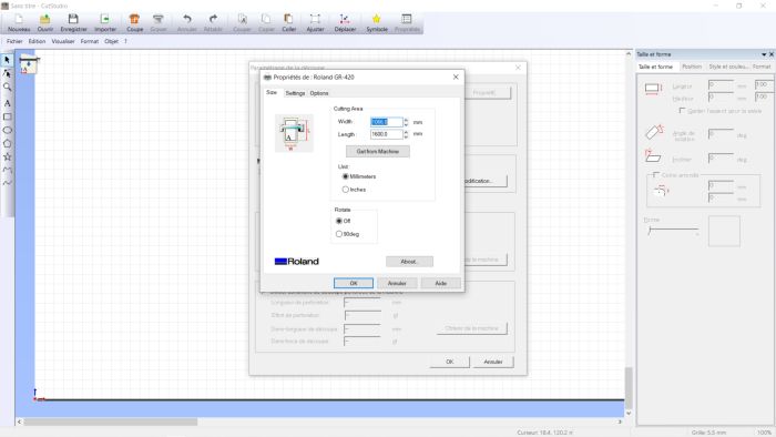
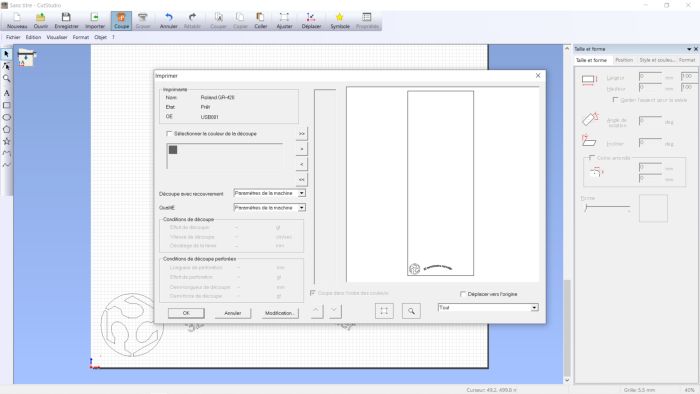
Passage on the software of our lasercut “gravostyle”.
Open the software
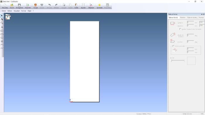
Set the dimensions of our material
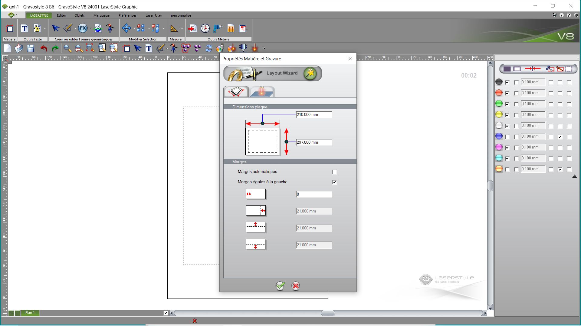
Set margins to 0
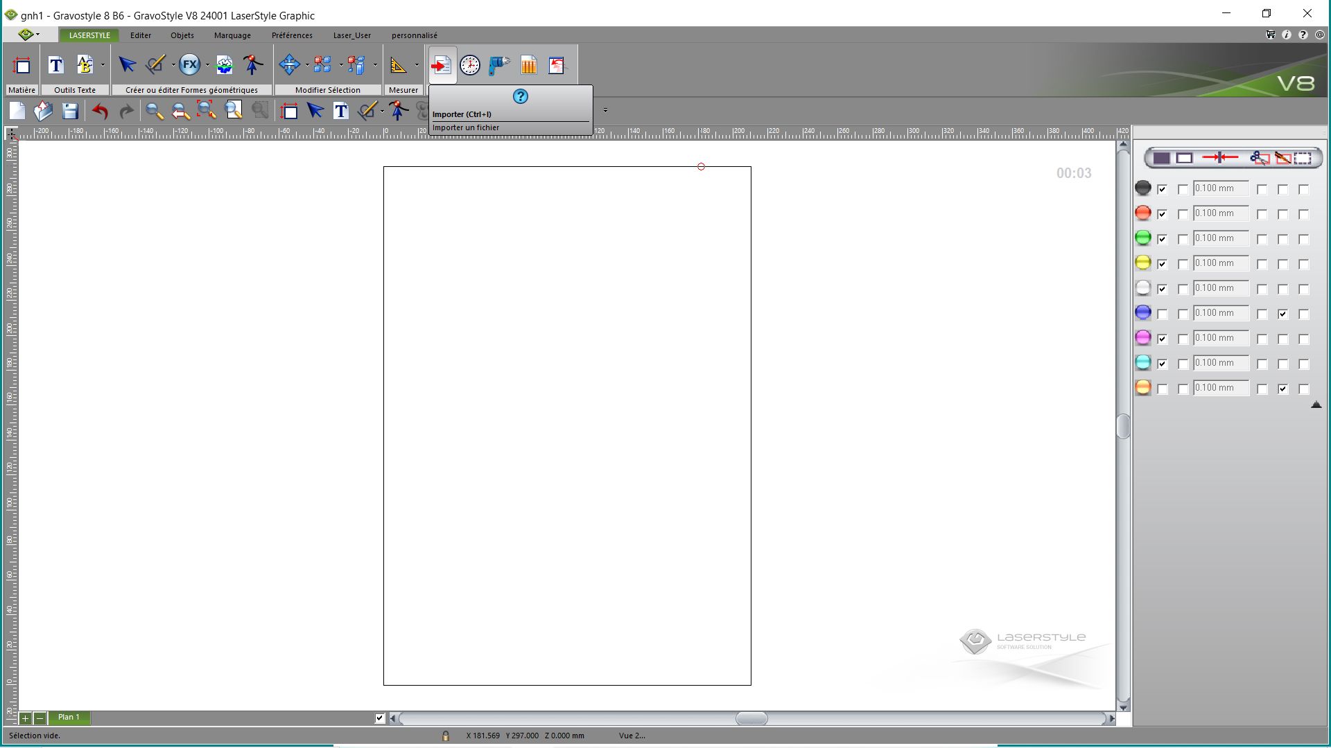
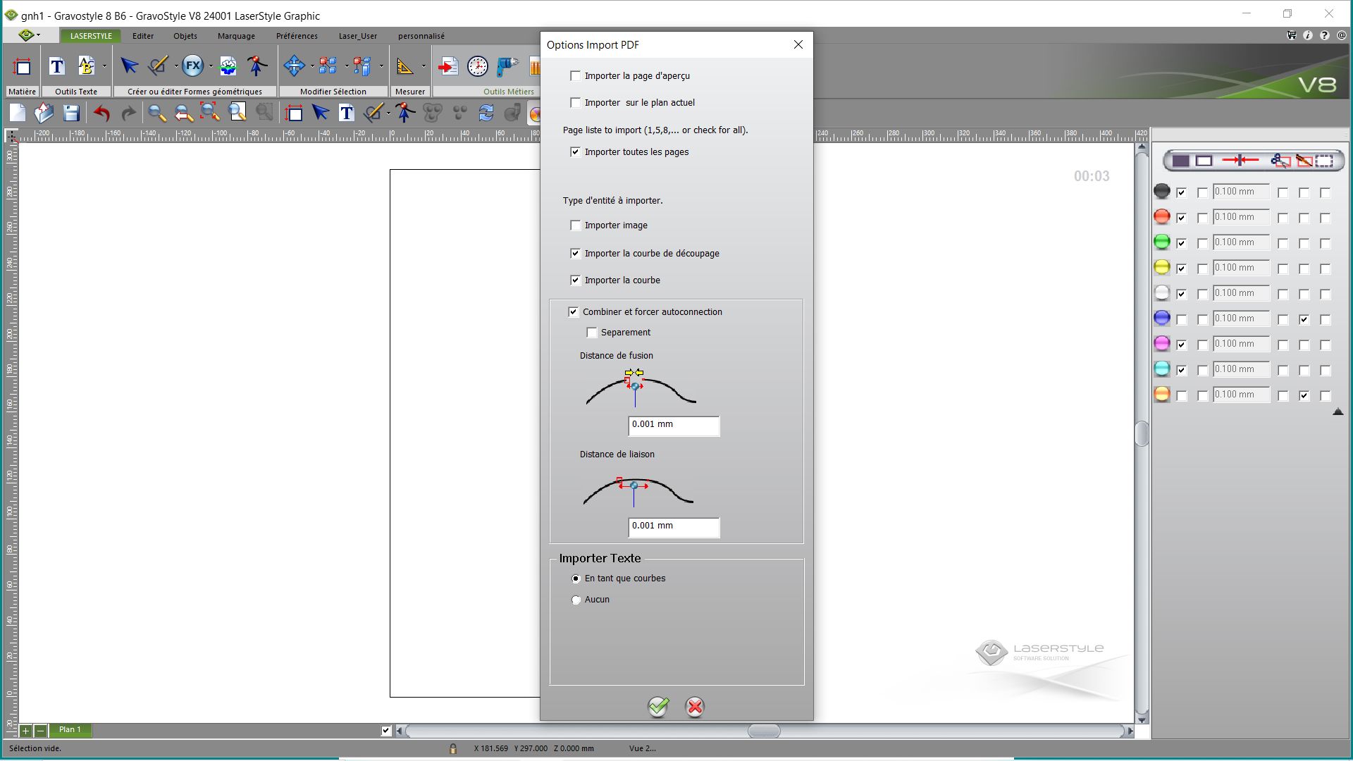
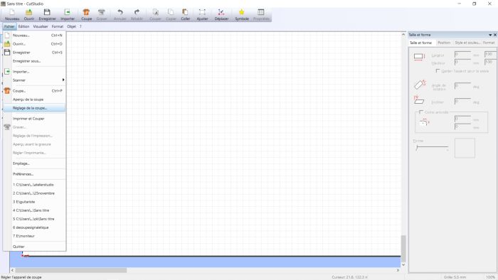
Import the file
Select the type of file
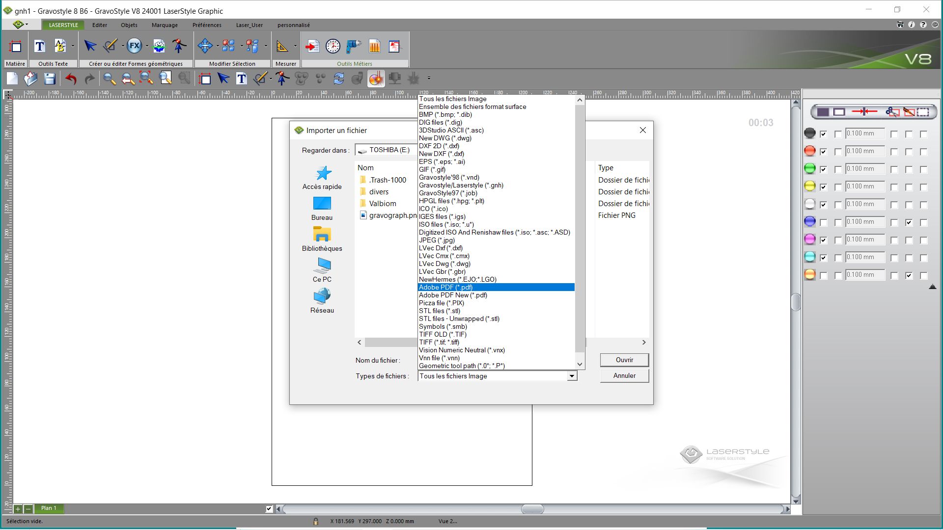
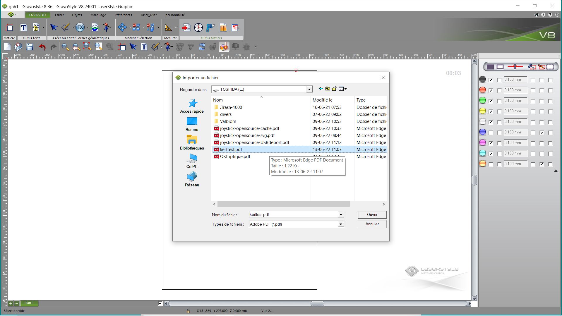
Validate
We apply a colour, and then we define the work to be done (which goes from engraving to cutting and marking)
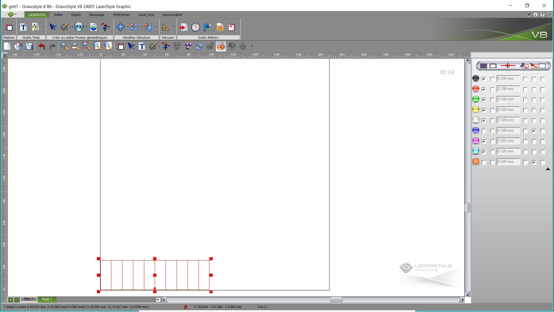
the work is positioned
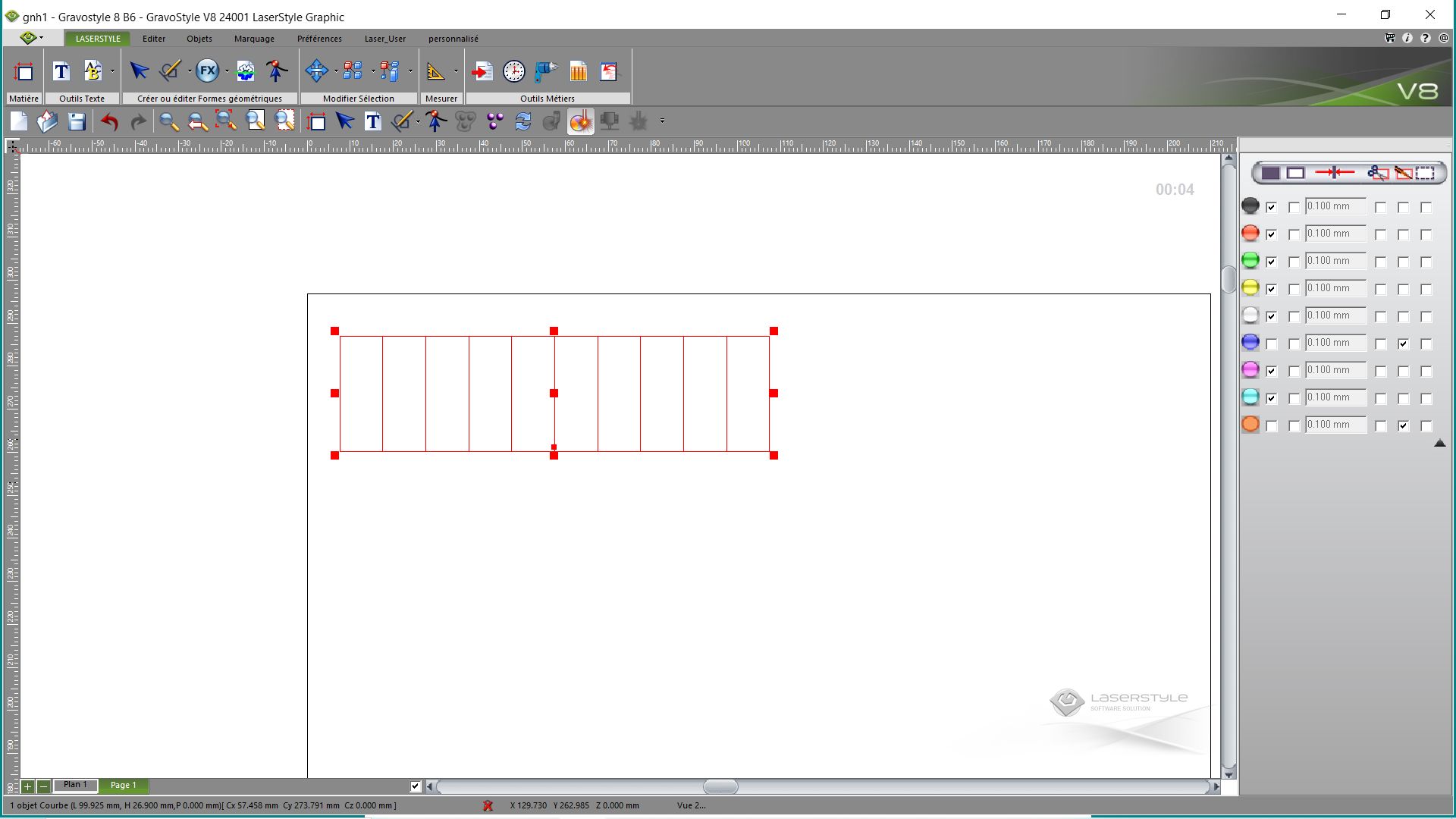

don’t forget to record your work
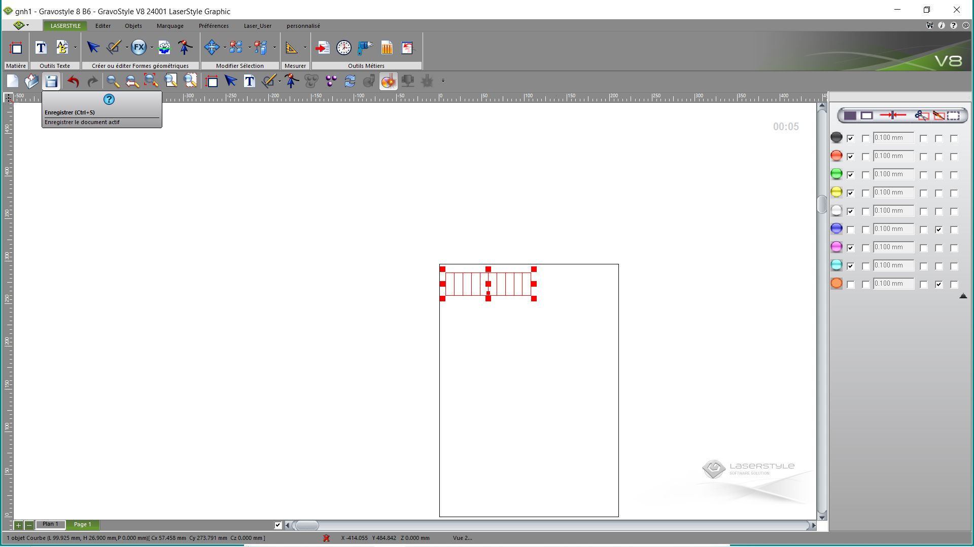
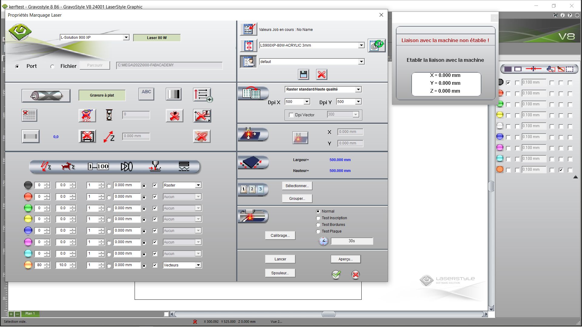
we launch the parameters for the machine. We click on default. We indicate the values for the cutting.
Gravostyle works in percent.
The values here for our material are : - Power 80 %. - Speed 10 %.
gravograph-machine1_r.jpg gravograph-machine2_r.jpg gravograph-machine3_r.jpg
the work to be done is checked.
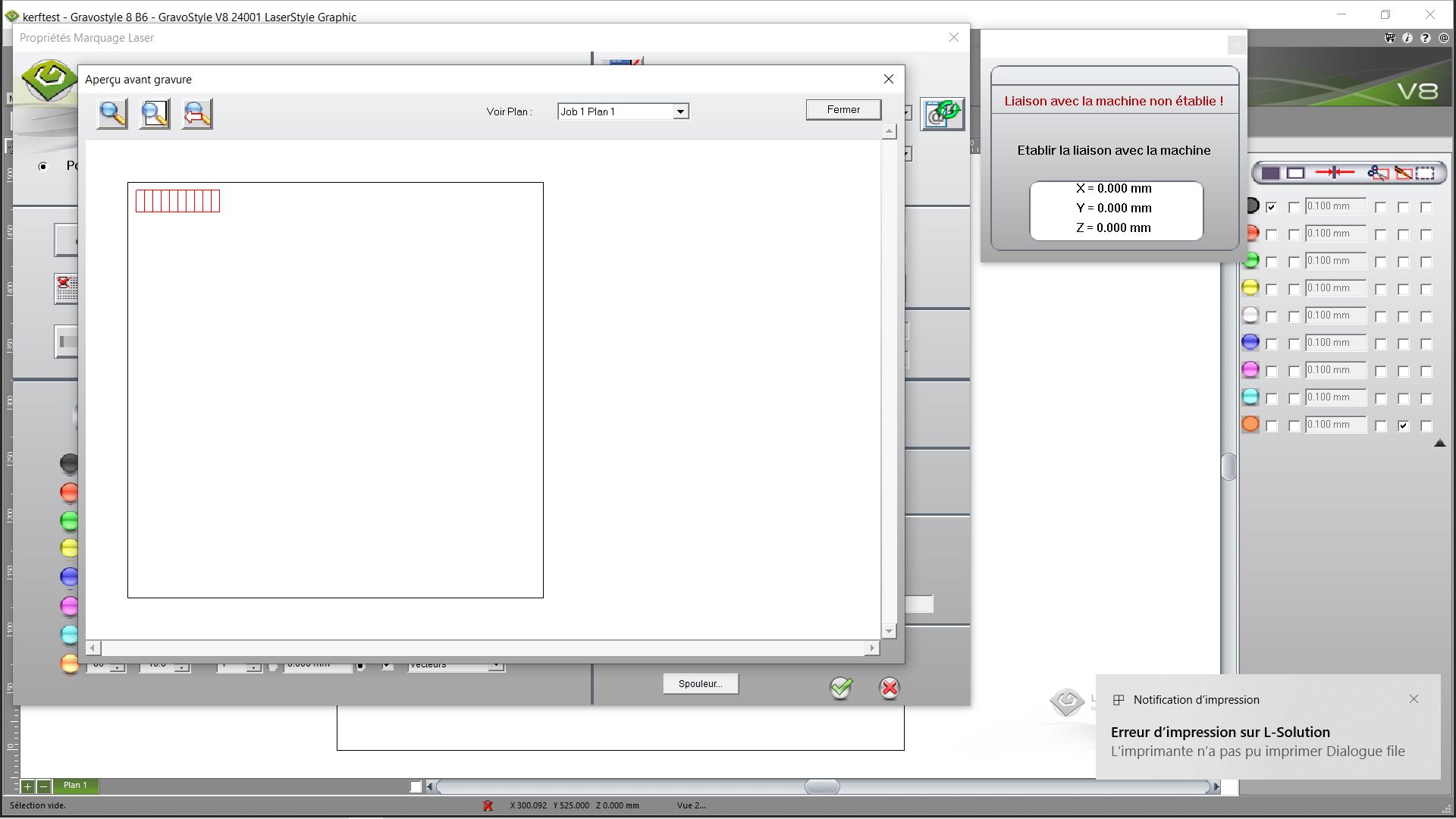
Thanks to this check, we also obtain the estimated working time.
Result ; I measure the 10 tabs and ?
Here is the measurement :
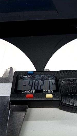
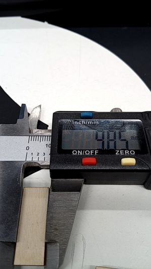
100 mm - 98.21 mm = 1.79 mm
1.79 mm / 10 = 0.178 mm
kerf = 0.18 mm ~0.2 mm
Individual Assignment
- Vinyl cutter - make a laptop sticker design, vectorize, cut using vinyl cutter
- Laser Cutter - Parametric modeling of Press-Fit Kit, cut Press-Fit pieces out of poplar plywood 4mm
Lasercut
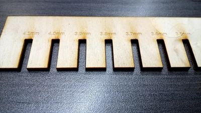
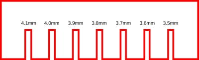
Creation of a test comb to validate the kerf for nesting, for example
In inkscape, I create a design that will allow me to test the nesting. I know that my kerf is 0.2mm, so for an interlocking design, we do x2 because two cuts.
So normally, for 4mm poplar plywood, I need to make a 3.6mm notch for everything to fit together properly.
file : kerf comb
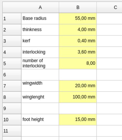
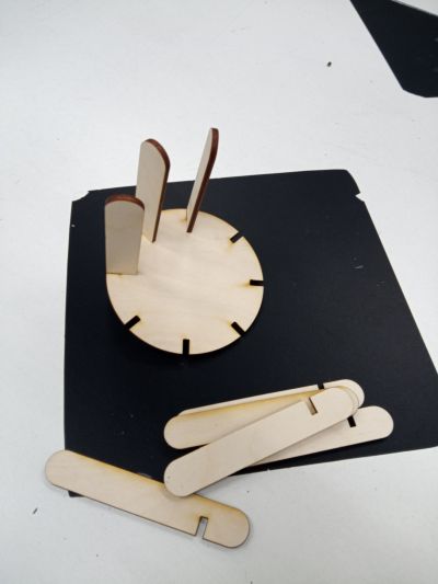
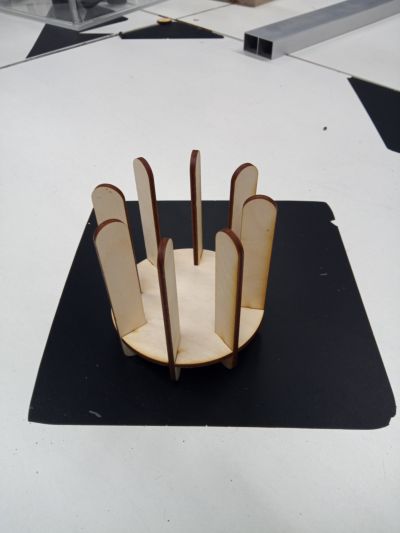
Creation of a parametric object
a candle holder To exploit the parameters of freecad; I decided to draw a candle holder fully customizable.
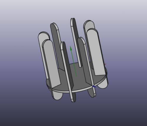
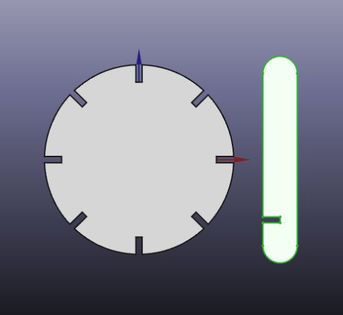
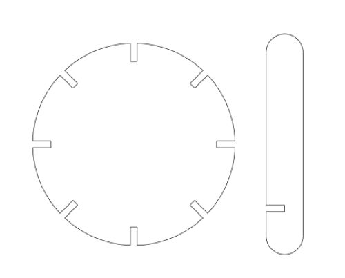
Result :


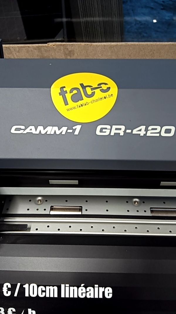
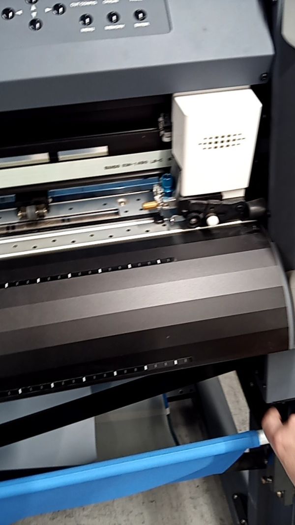
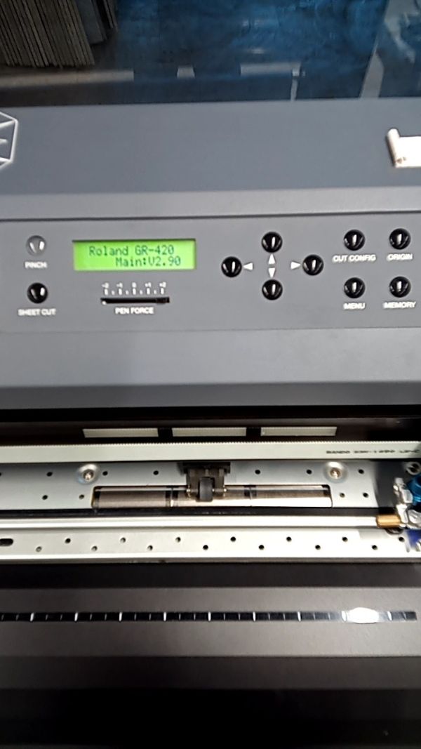
Vinyl cutter
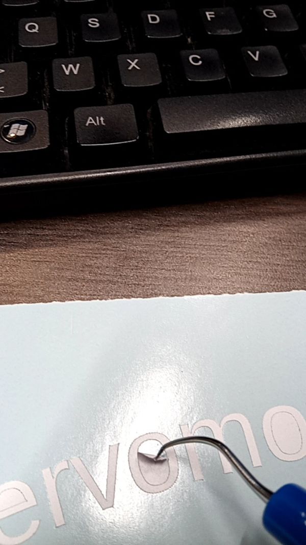
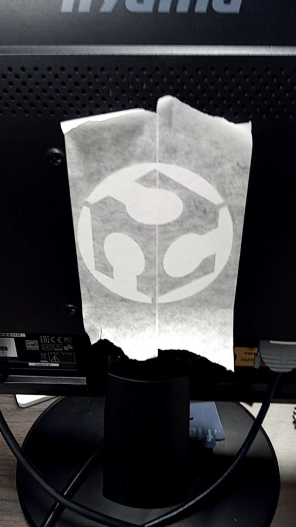
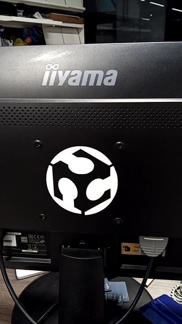
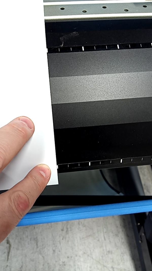
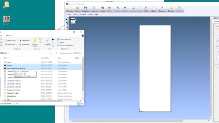
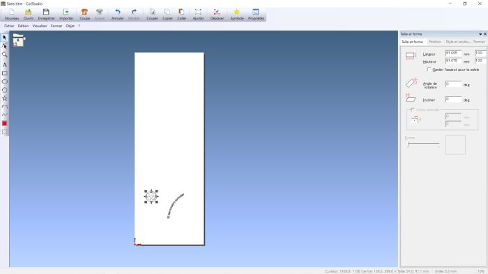
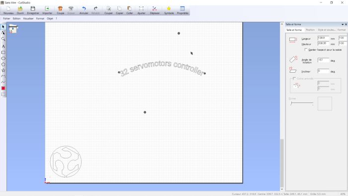
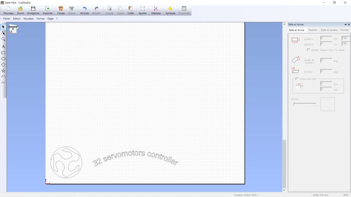
For the use of the vinyl cutter, I took the fabacademy logo (expressly in image) to go through the vectorisation and modification steps.
I use Inkscape for this
![]()
![]()
![]()
![]()
File : vinilcutlogofabacademy.svg

Attention, if you want to make FLEX (vinyl for teeshirt), do not forget to make a mirror effect
the paper is weeded (the excess is removed)