13. Input Devices
Individual assignment :
- Measure something: add a sensor to a microcontroller board that you have designed and read it
Group assignment :
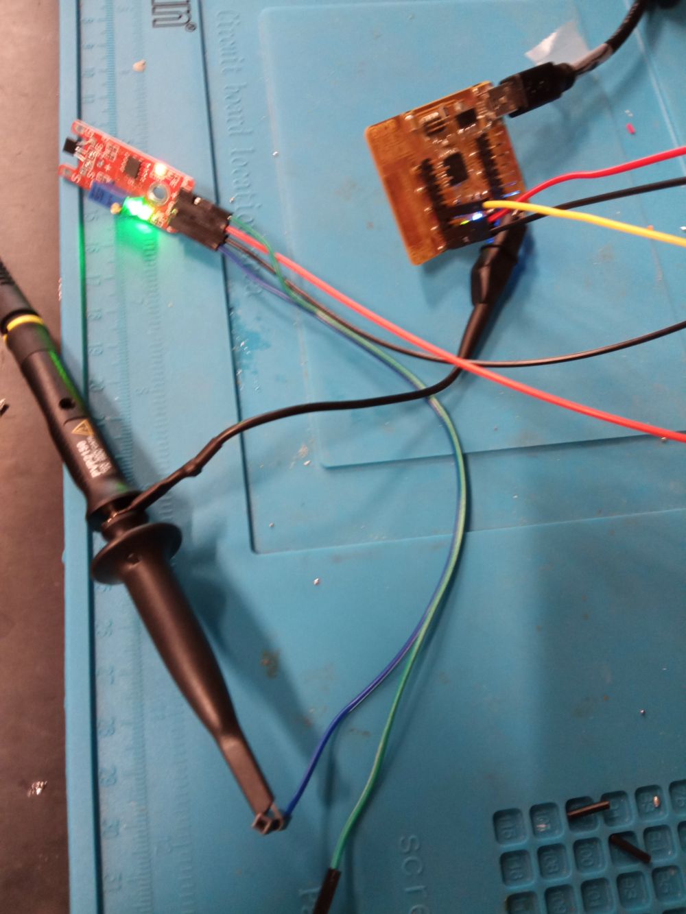
- Probe an input device’s analog levels and digital signals
Individual assignment
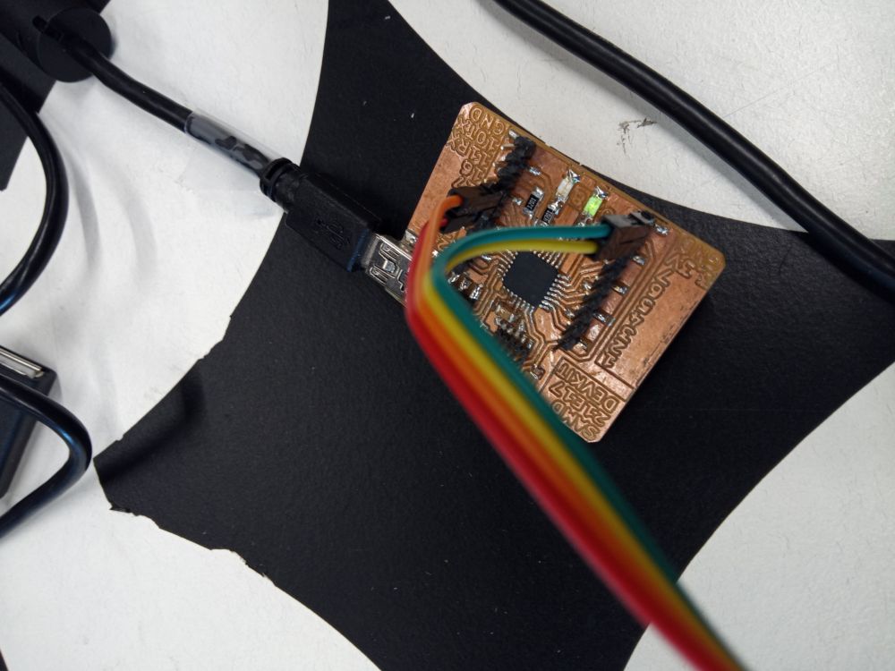
I use the SAMD21E17/E18 devkit board to Quentin Bolsée(LINK )
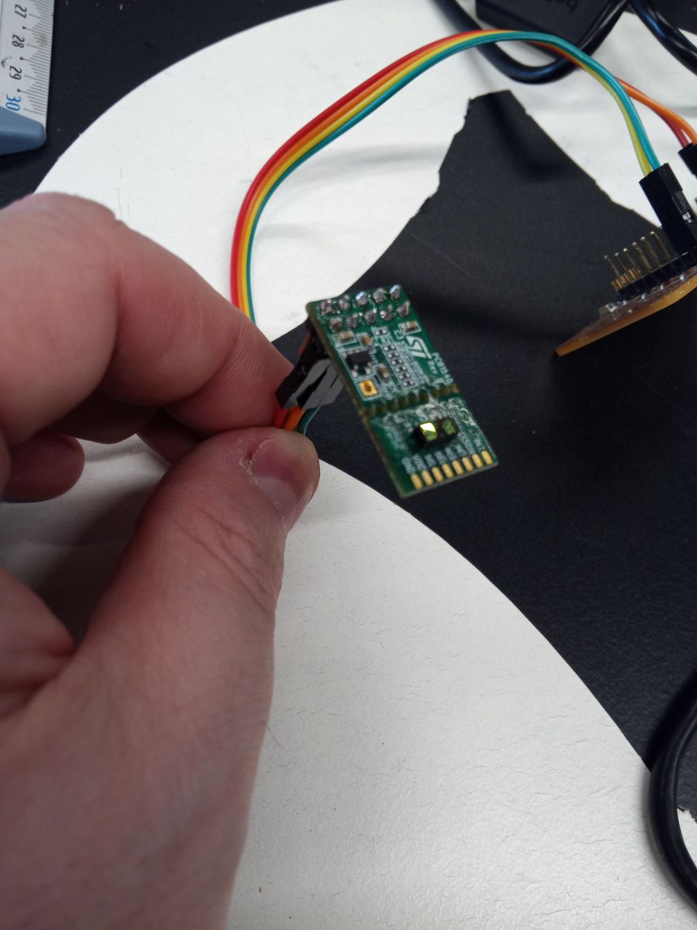
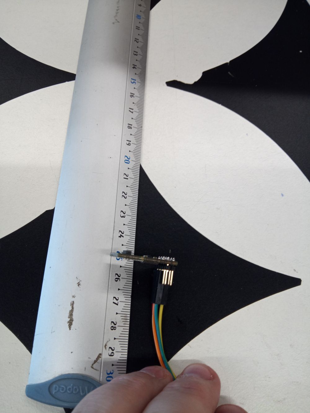
VLS3L1X Laser Distance Sensor
the VLS3L1X is perfect for making accurate measurements.
Here is the code to animate it.
#include <Wire.h>
#include <VL53L1X.h> // https://www.arduino.cc/reference/en/libraries/vl53l1x/

VL53L1X sensor;

void setup() {
  while (!SerialUSB) {

  }
  SerialUSB.begin(115200);
  Wire.begin();
  Wire.setClock(400000); // 400 KHz I2C
  sensor.setTimeout(500);
  if (!sensor.init()) {
    SerialUSB.println("Failed to detect and initialize sensor!");
    while (1);
  }

  sensor.setDistanceMode(VL53L1X::Long);
  sensor.setMeasurementTimingBudget(50000);
  sensor.startContinuous(50);
}

void loop() {
  sensor.read();
  SerialUSB.println(sensor.ranging_data.range_mm);
  delay(30);
}
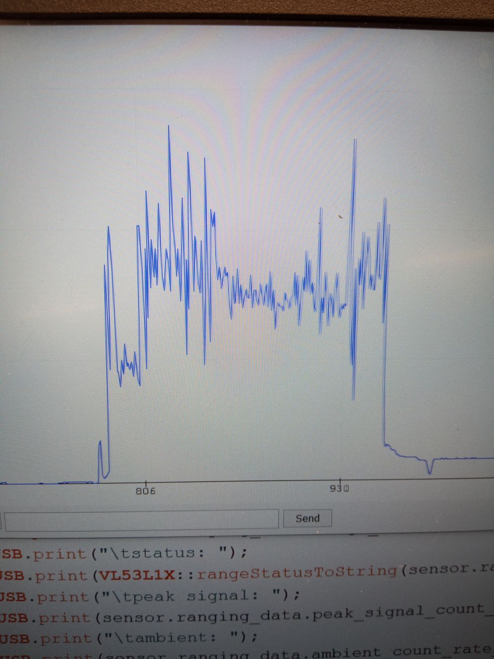
After connecting to our development board, we look at the values with a 30 cm slat to see how the laser reacts. It’s quite amazing to see the precision of the laser
we see here, the values that change when we approach or recede the sensor
Hall effect sensor
A Hall effect sensor measures a magnetic field variation
code :
#define PIN_ANALOG 7
#define PIN_LED 8

void setup() {
  SerialUSB.begin(115200);
  pinMode(PIN_ANALOG, INPUT);
  pinMode(PIN_LED, OUTPUT);
}

void loop() {
  int analogValue = analogRead(PIN_ANALOG);
  SerialUSB.println(analogValue);

  digitalWrite(PIN_LED, analogValue > 550 ? HIGH : LOW);
  delay(30);
}
serial plotter in Arduino IDE
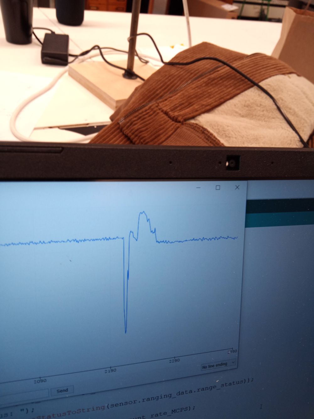
Measuring the sensor variation with a magnet
Here we see the oscilloscope variations of the hall effect device. Here after in the video the manipulation with a magnet to have the variations on the screen of the oscilloscope
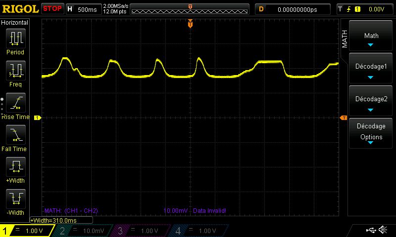
Here are some videos to show the hall effect on the oscilloscope
Hall Effect + Neopixel
code :
//define neopixel ring

#include <Adafruit_NeoPixel.h>
#define PIN        6
#define NUMPIXELS 12
Adafruit_NeoPixel pixels(NUMPIXELS, PIN, NEO_GRB + NEO_KHZ800);
#define DELAYVAL 100

#define PIN_ANALOG 7
#define PIN_LED 8

void show_level(int val, int val_min, int val_max){
  int c=map(val,val_min, val_max,0,NUMPIXELS);
  pixels.clear();
  for(int i=0; i<c; i++) {
    pixels.setPixelColor(i, pixels.Color(50, 50, 0));
  }
  pixels.show();
}


void setup() {
  SerialUSB.begin(115200);
  pinMode(PIN_ANALOG, INPUT);
  pinMode(PIN_LED, OUTPUT);

  pixels.begin();
  pixels.clear();
}

void loop() {
  int analogValue = analogRead(PIN_ANALOG);
  SerialUSB.println(analogValue);

  show_level(analogValue, 500, 650);

  delay(10);
}
Download : hall_pixel
Here is the result on video. The closer you get to the sensor, the more LEDs are displayed
Group assignment
Group Link : link
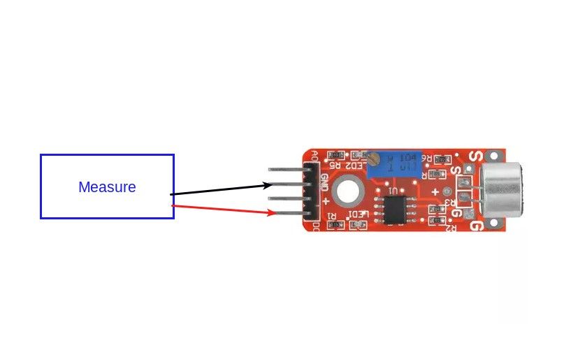
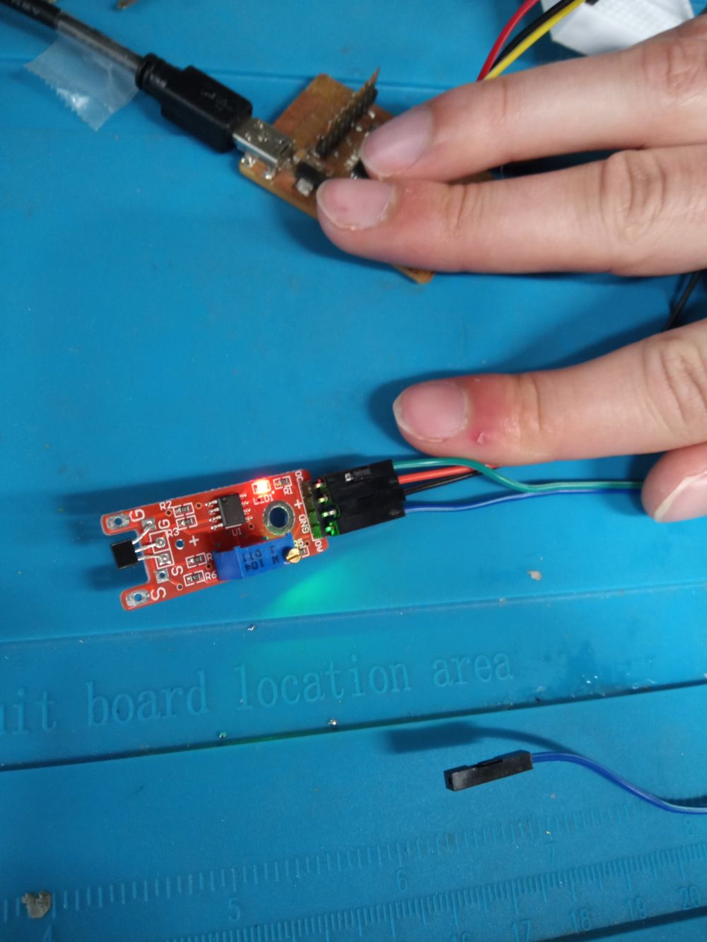
For this week’s work I decided to work with a KY-037 sound detector - I added a neopixel ring to light up when a dB threshold was exceeded.
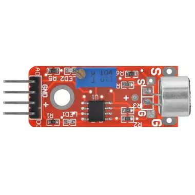
Technical Datasheet of the KY-038 / KY-037 Sound Sensor
Before we can connect the KY-037 sound sensor to any microcontroller, we have to know the technical specifications of the sensor. The following table shows the datasheet of the KY-037
| KY-037 | |
|---|---|
| Operation Voltage | 3.3V…5V |
| Frequency Response | 50 Hz…20 kHz |
| Impedance | 2.2 kΩ |
| Sensitivity | >48…66 dB |
KY-037 Operation Voltage
The operation voltage is between 3.3V and 5V, what makes the sound sensor compatible to Arduino microcontroller with an operation voltage of 5V.
KY-037 Frequency Response
The frequency response is exceptionally large and between 50Hz and 20kHz and for non-experts hard to imagine. But you can play test tones that are oscillating in a square wave descending 20kHz through 20Hz. To set the frequency response in relation to your human speed, the frequency range for a man speaking is between 100Hz and 120Hz and for women around 300Hz.
KY-038 / KY-037 Sensitivity
The sensitivity of the sound sensor is the smallest absolute amount of change that can be detected.
KY-037 Module Pinout and Electronic Components
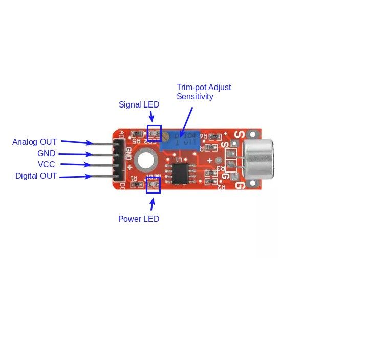
The KY-037 module consists of the following electronic parts:
- 4 output pins that connect the sound sensor to a microcontroller.
- A0: Analog pin to transfer an analog signal.
- G: Ground to connect the sound sensor to ground with the microcontroller.
- +: Pin for the operation voltage between 3.3V to 5V regarding to the technical datasheet.
- D0: Digital output based on a predefined threshold through the potentiometer and the operation voltage of the microcontroller.
- Potentiometer to define a threshold for the digital output pin.
- 2 LEDs to indicate that the module is operating and to indicate the status of the digital pin.
- 6 Resistors to prevent LEDs for too high voltages and to operate as voltage dividers.
- LM393 dual comparator to compare the signal created by the microphone with the predefined value through the potentiometer and to control the status of the LED that indicates the status of the digital output.
- Microphone that generates the sound signal.
Code
//define neopixel ring

#include <Adafruit_NeoPixel.h>
#define PIN        6
#define NUMPIXELS 12

Adafruit_NeoPixel pixels(NUMPIXELS, PIN, NEO_GRB + NEO_KHZ800);
#define DELAYVAL 100

//define big sound

const int MIC = 0; //the microphone amplifier output is connected to pin A0
int adc;
int dB, PdB; //the variable that will hold the value read from the microphone each time


void setup() {
Serial.begin(9600); //sets the baud rate at 9600 so we can check the values the microphone is obtaining on the Serial Monitor
  pinMode(3, OUTPUT);

  pixels.begin();
}

void loop(){
  pixels.clear();

  PdB = dB; //Store the previous of dB here

adc= analogRead(MIC); //Read the ADC value from amplifer
//Serial.println (adc);//Print ADC for initial calculation
dB = (adc+83.2073) / 11.003; //Convert ADC value to dB using Regression values
  pixels.clear();


if (PdB!=dB)

//Serial.println ("les db sont de:",dB);
Serial.println (dB);


if (dB>50) //define db for turn the neopixel LED on high
{
  digitalWrite(3, HIGH);   // turn the LED on (HIGH is the voltage level)
  delay(100);                       // wait for a second
  digitalWrite(3, LOW);


  for(int i=0; i<NUMPIXELS; i++) {

    pixels.setPixelColor(i, pixels.Color(150, 150, 0));
    pixels.show();
    delay(DELAYVAL);
    pixels.clear();


  }

}
//delay(100);

}
Download : Big Sound
Measure