12. Mechanical design, machine design
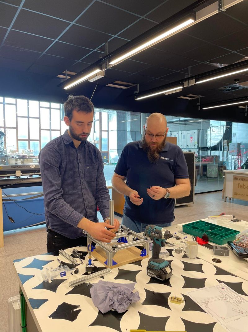
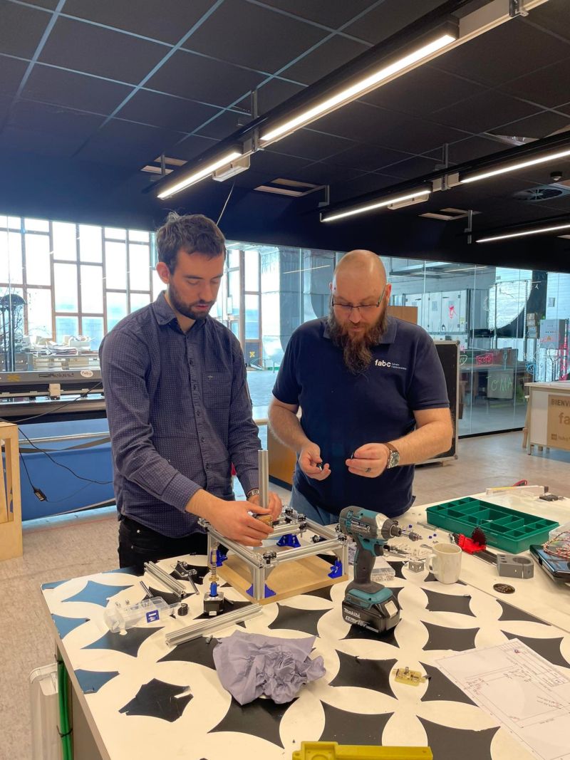
For these two weeks of work, with my instructor Quentin, we agreed to work on the Urumbu project.
Link to ULB site : link
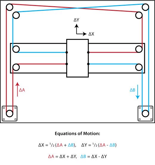
What is the Urumbu Project ?
The original project is a 2D core xy motion system using serialstep. Urumbu Project

Action plan
- Modification of the xy-carriage to support an object
- Creating a z-axis to put on the xy-axis
Modification of the xy-carriage to support an object
We need to widen the carriage in order to be able to add an additional tool or axle while avoiding the overhang.
Indeed, on the starting model there is only one bar for the carriage and therefore it is quite difficult to avoid the overhang.
Base model
I created a base to attach the machine to. This base was drawn on Freecad and machined on the CNC.
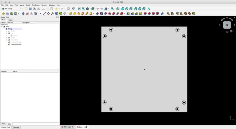
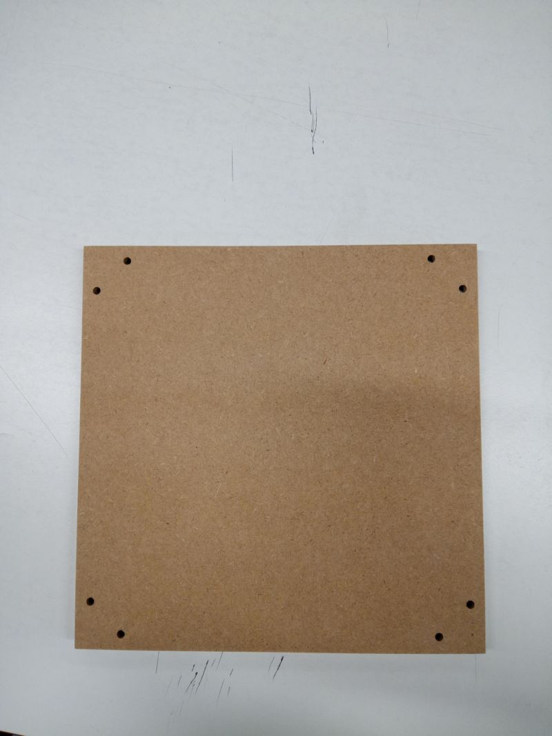
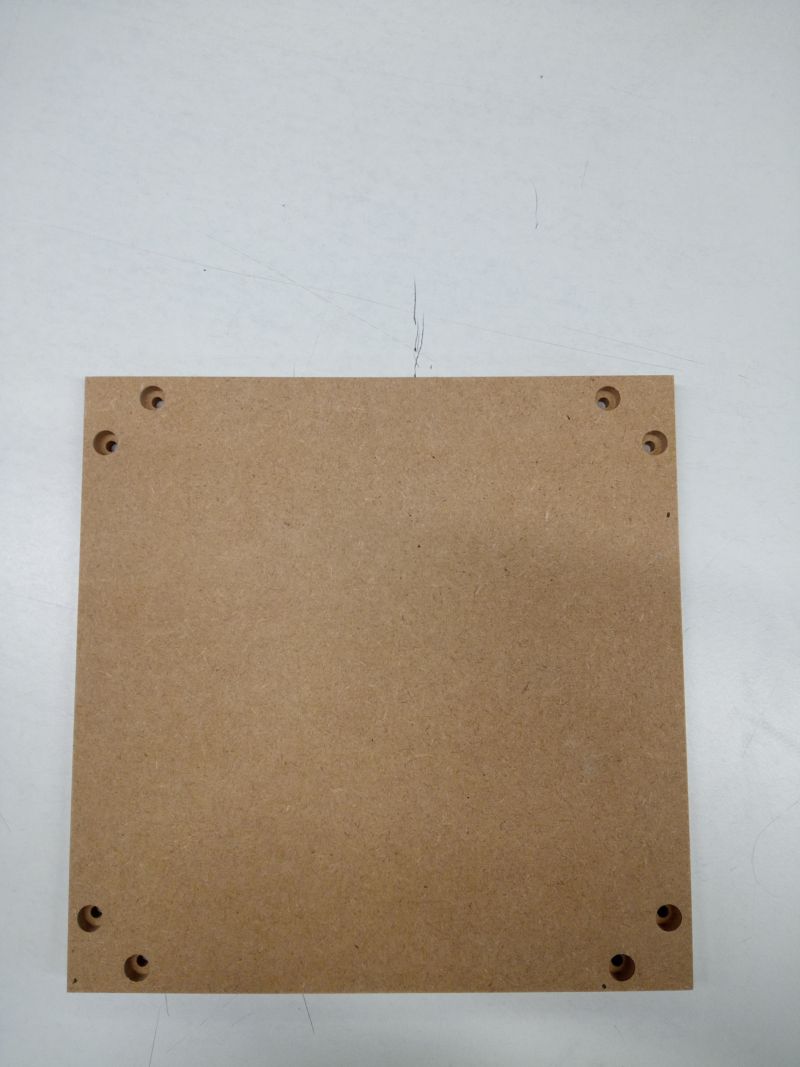
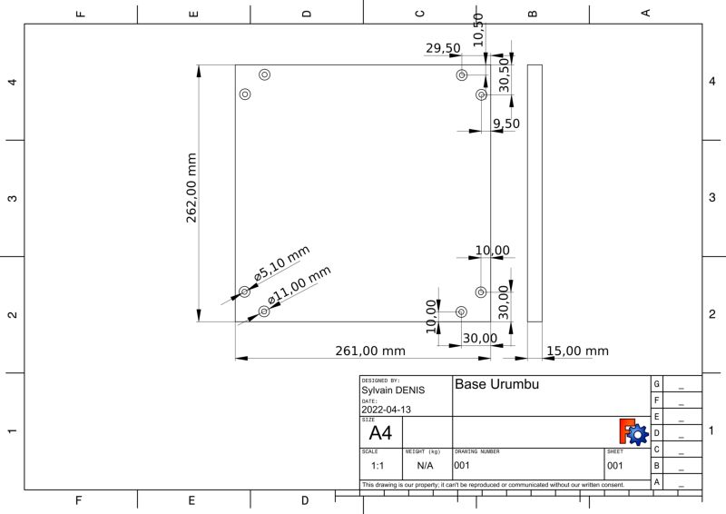
Files :
Base feet
I have drawn and printed the base fixing feet
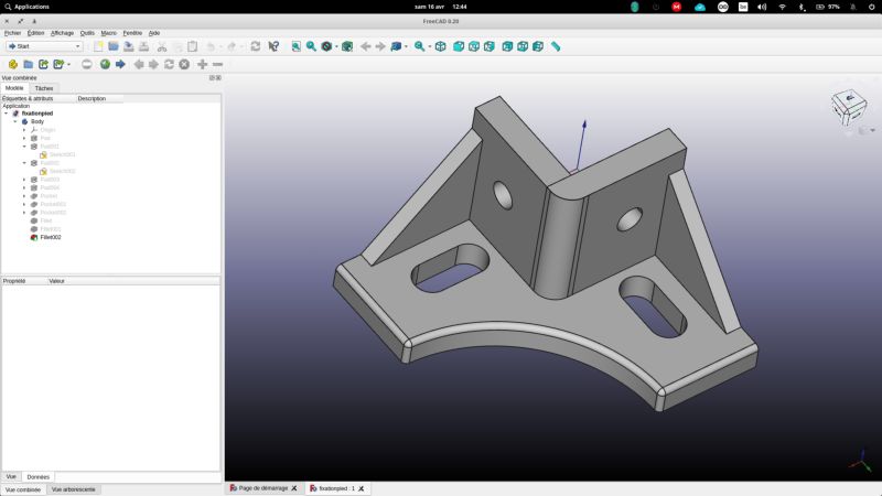
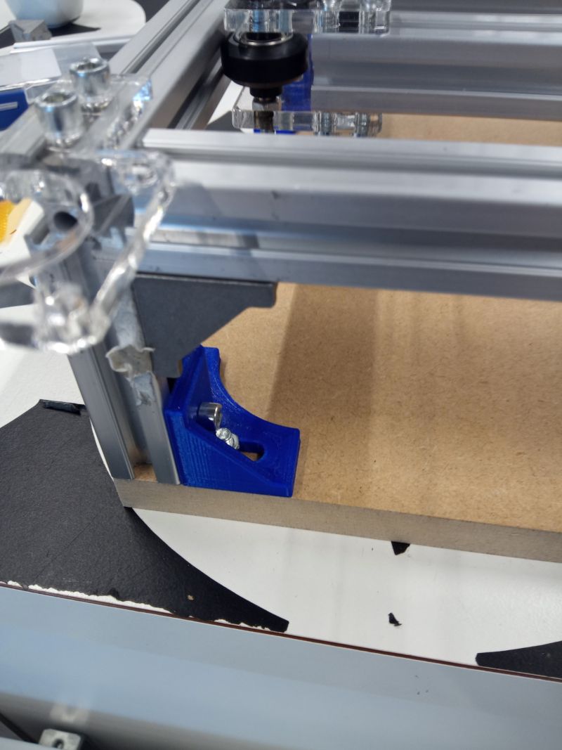
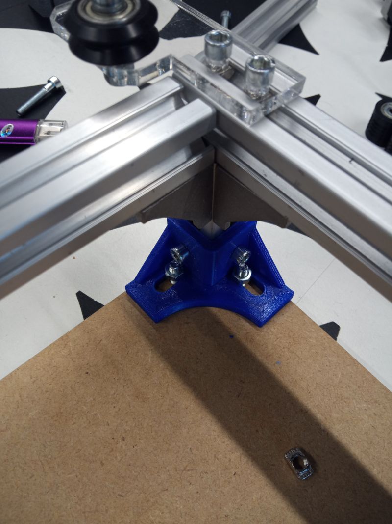
Files :
Success
Base stability : OK
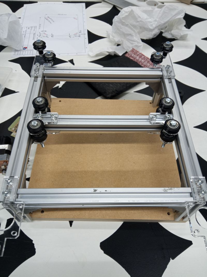
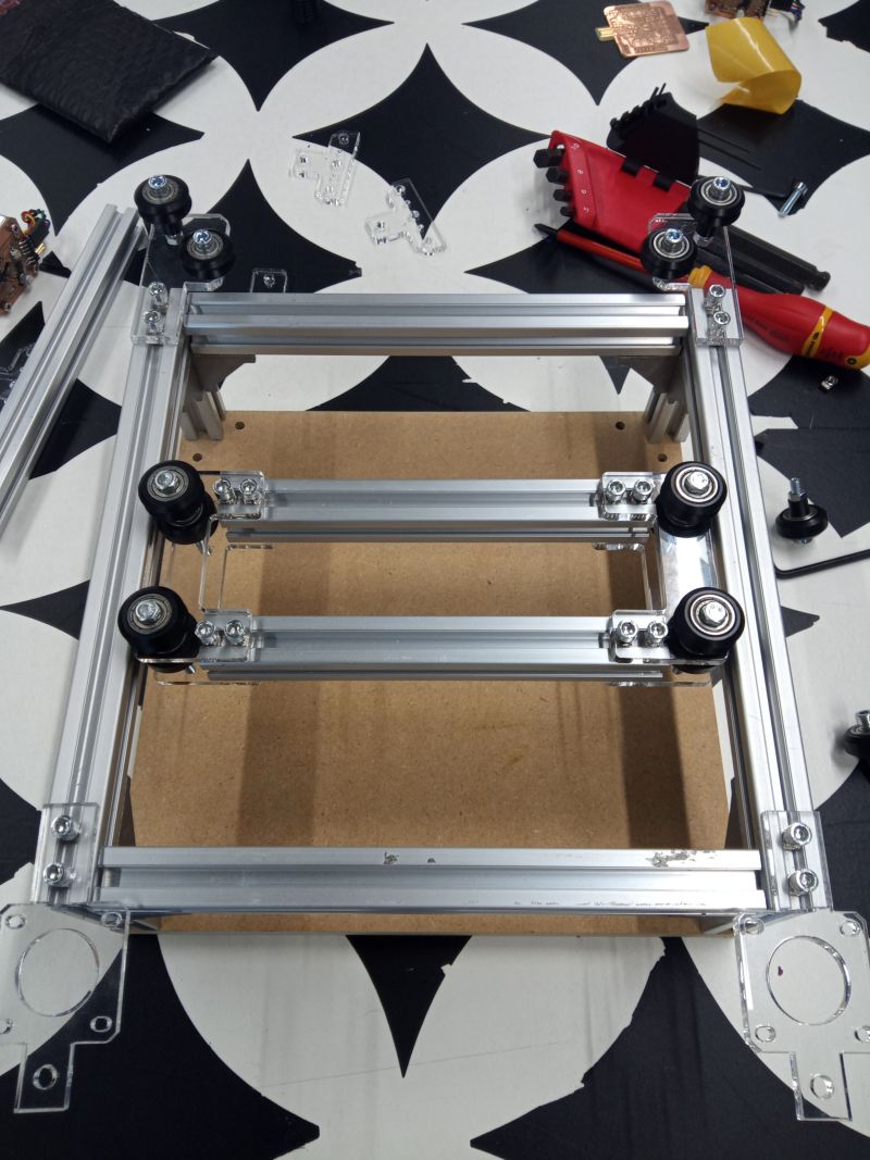
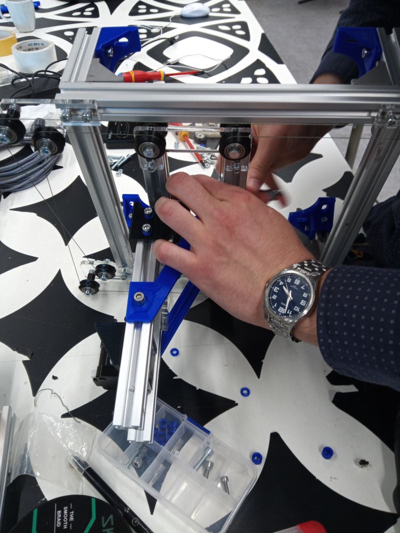
Modification of the carriage
We need to cut the new supports for the trolley to size with the aluminium profiles. We have created a small template to cut these profiles correctly.
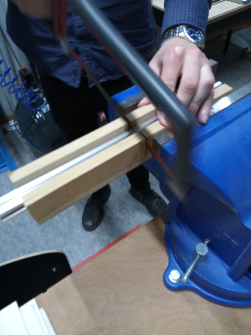
To define the width of the trolley, I redraw the profiles, the wheels to define the maximum width and the minimum position of the wheels
Files :
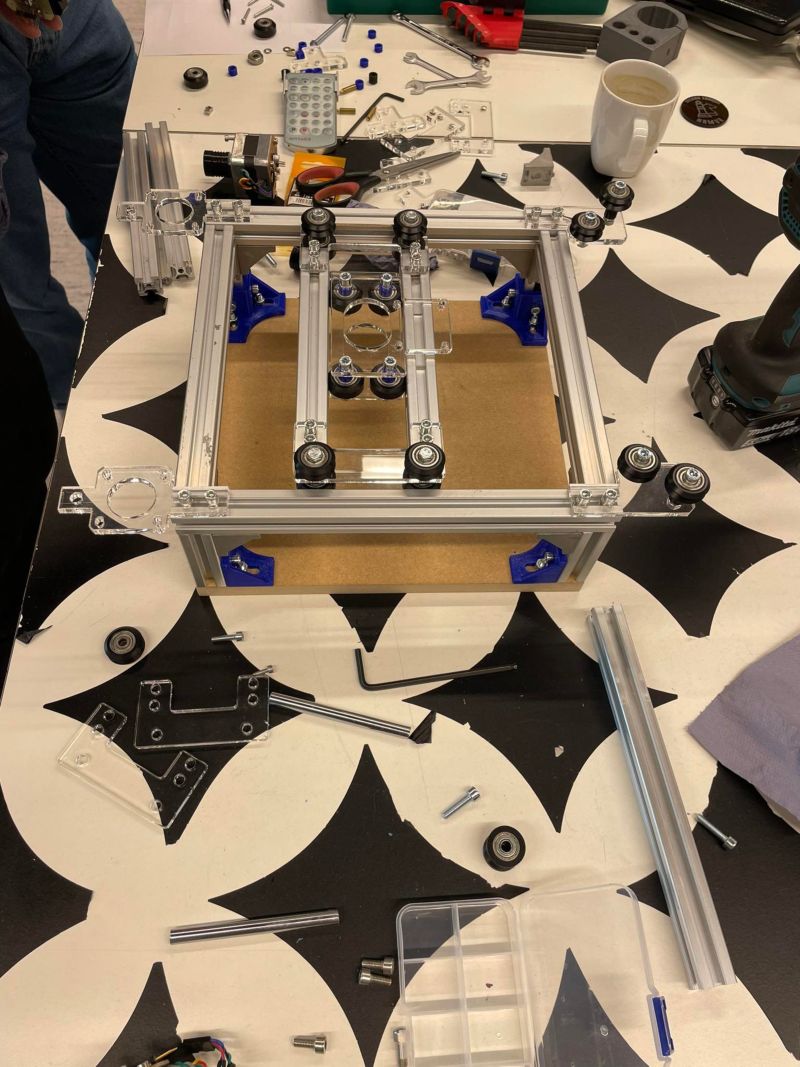
Assembly of the trolley for y-axis
It is useful to have a bracket to facilitate the subsequent assembly of the trolley
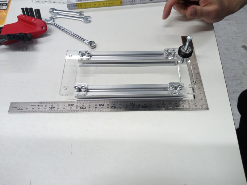
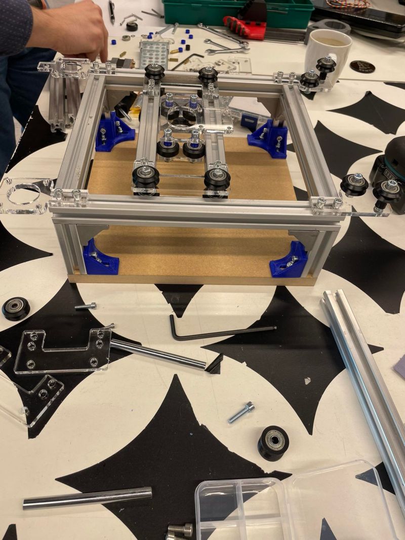
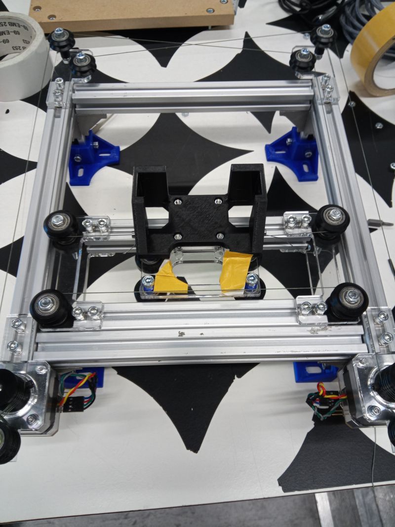
Carriage assembly for x-axis
Success
Carriage : OK
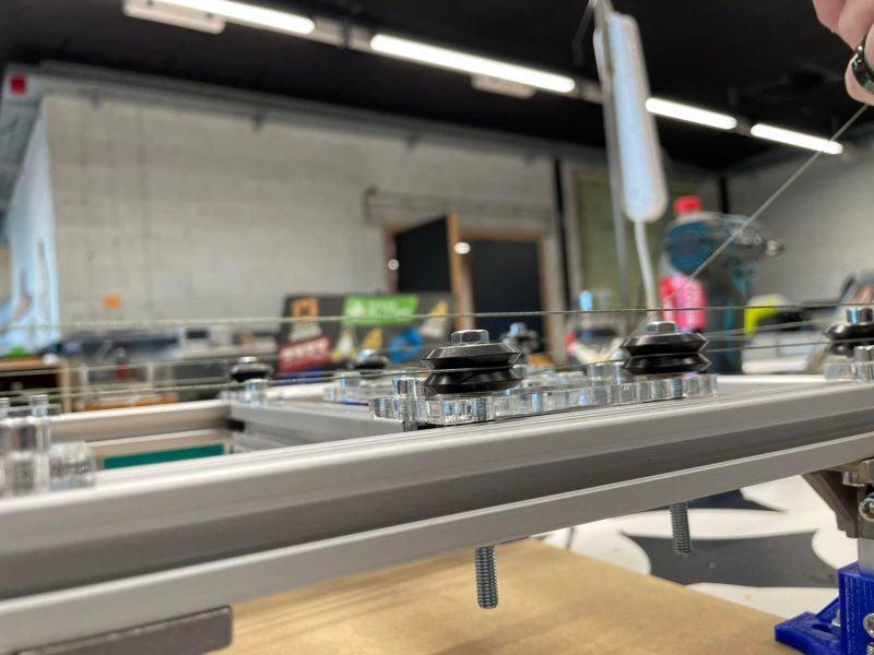
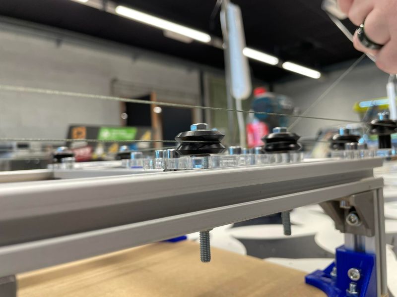
Mounting the motors and running the wire
Several hands are needed to pass the wire
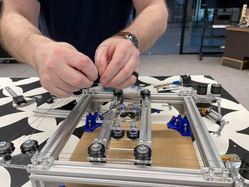
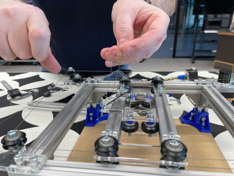
Success
it works manually
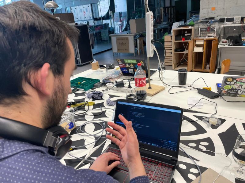
Testing with motors and code
Quentin sends some code to test the machine and ???
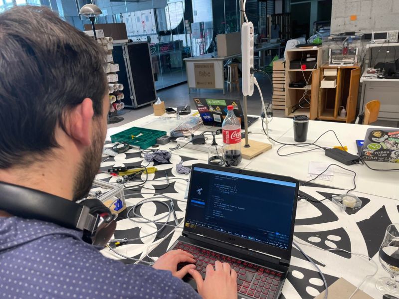
It’s alive
A circle
A square
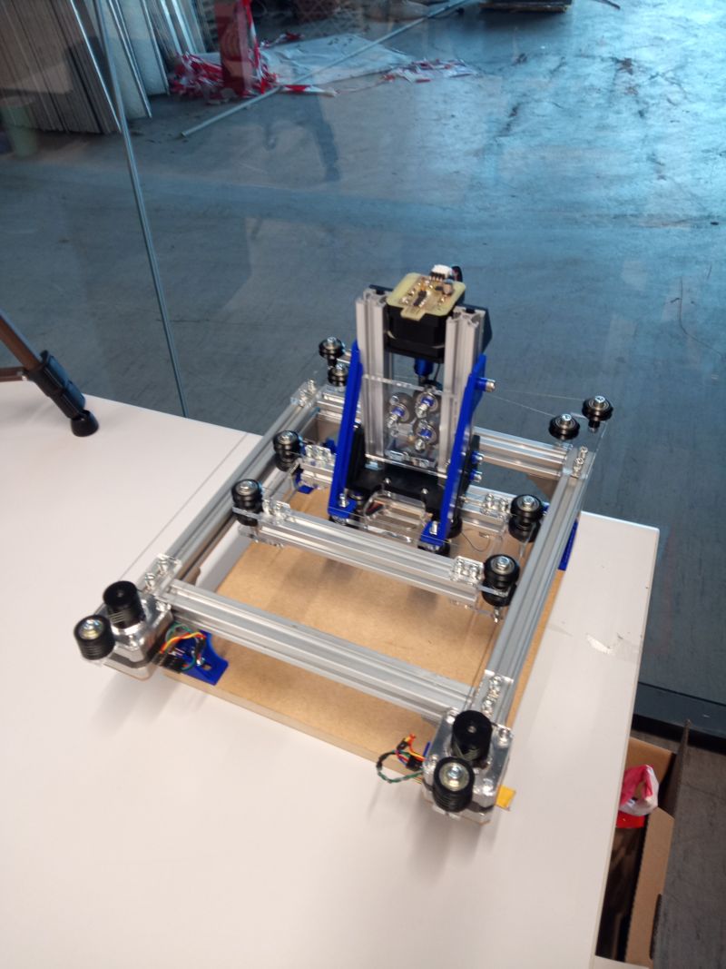
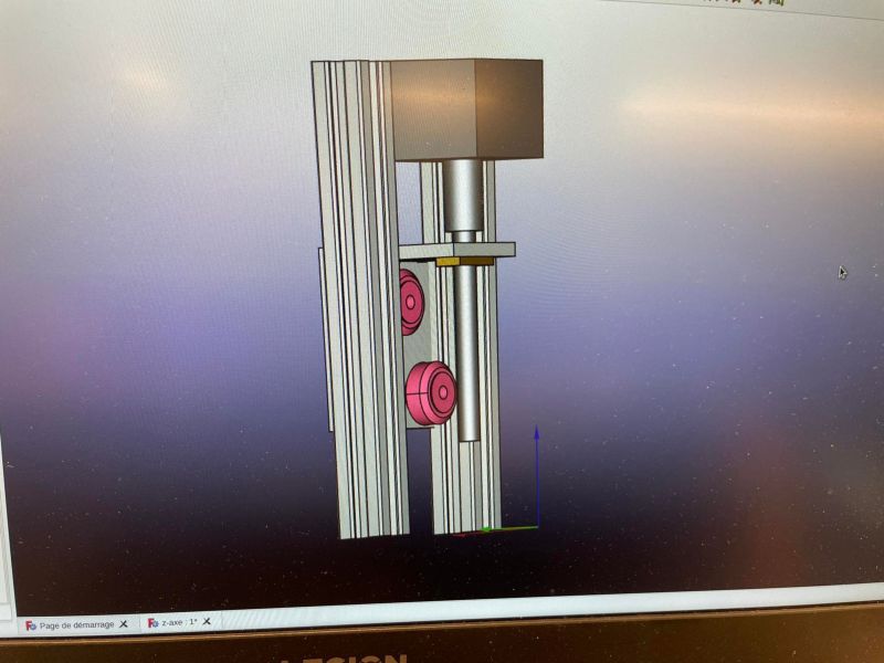
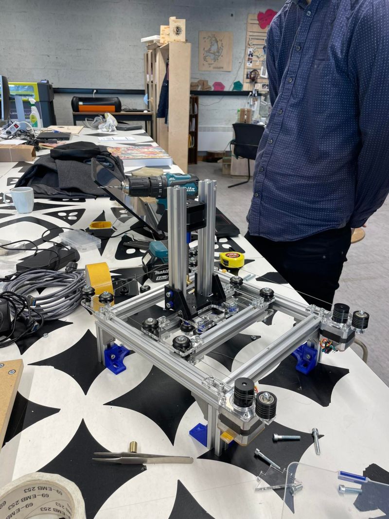
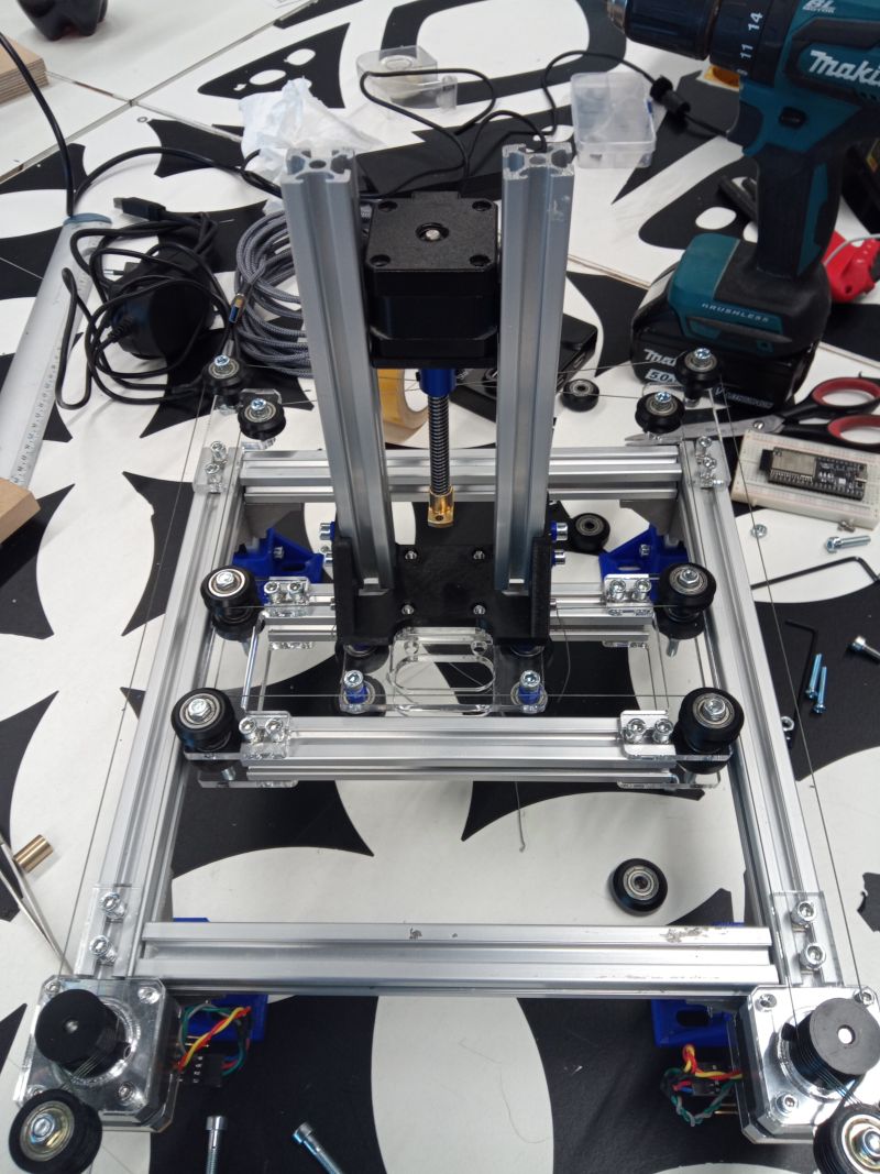
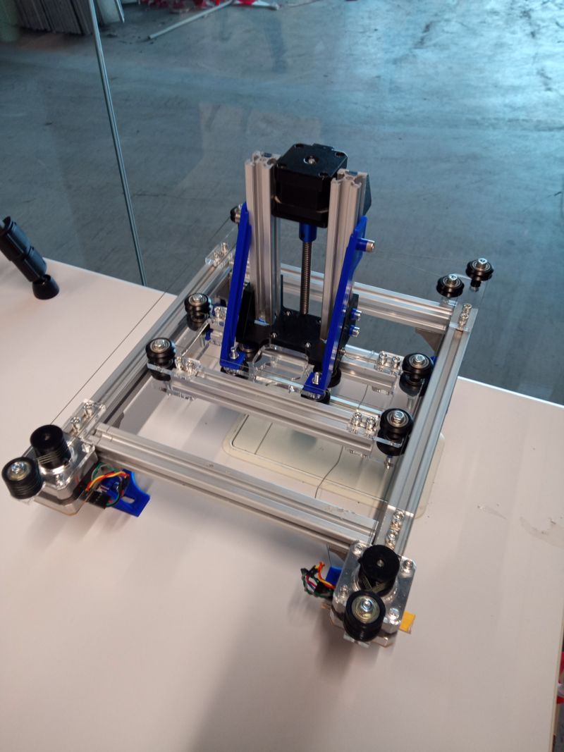
Axe Z
Now we move on to the stage of making the Z axis
Quentin arrived with this piece that will allow profiles to be held vertically
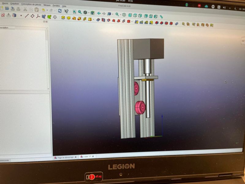
Drawing on Freecad to think about the possibilities of fixing the different components (profiles, wheels, motor, tool holder)
Reflexions
In reflection mode, to imagine the different types of fixings for the tool holder
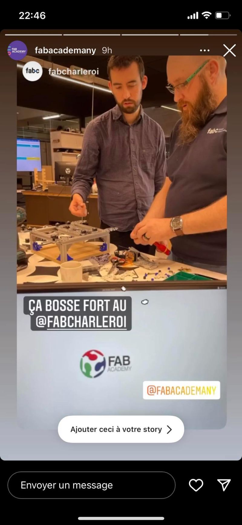
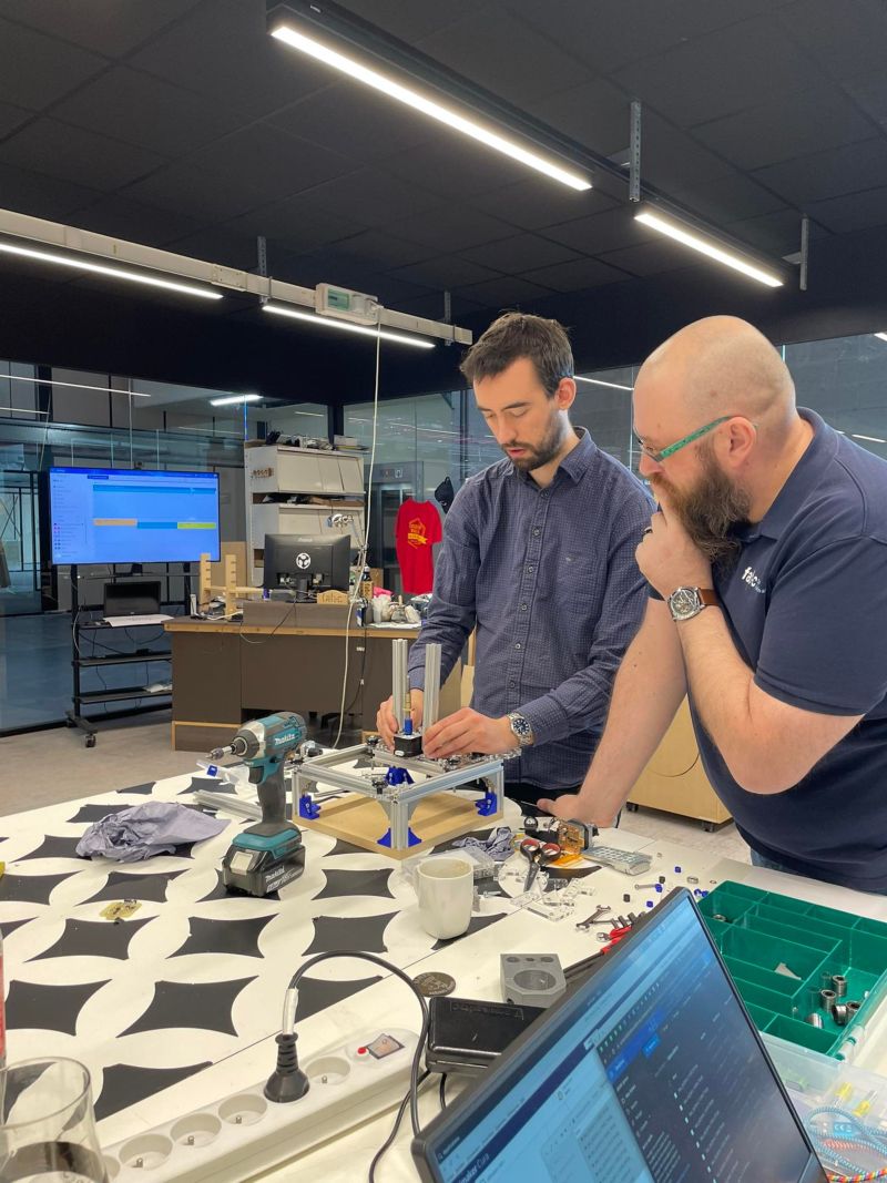
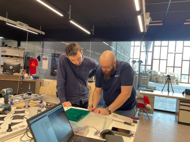
Teamwork finally pays off, we are now making good progress on the project
Little failure
Vibrations can be noticed, probably due to the weight of the engine? To remedy this, Quentin designed supports that we print directly
Result
It works, the vibrations are attenuated
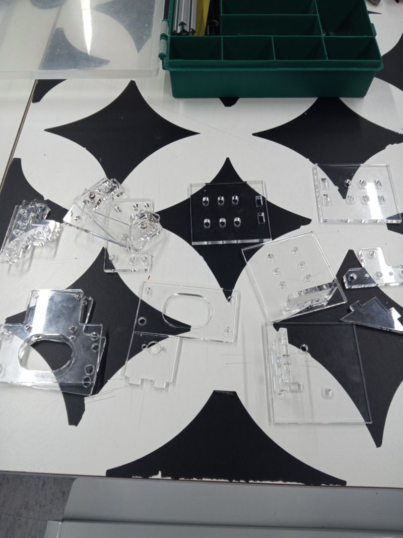
In the meantime, I draw the next cuts that will be used to fix the tools that will be linked via the motor’s worm gear

After several iterations, I finally arrived at a compromise
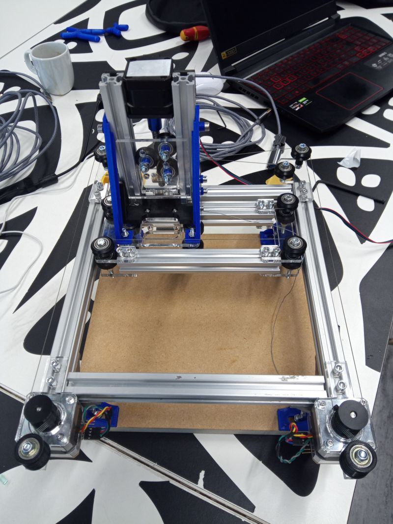
Final Result
This is the finished machine