8. Computer controlled machining
Objectives :
Group assignment :
- Do your lab’s safety training
- Test runout, alignment, fixturing, speeds, feeds, materials, and toolpaths for your machine
Individual assignment :
- Make (design+mill+assemble) something big (~meter-scale)
- Extra credit: don’t use fasteners or glue)
- Extra credit: include curved surfaces
Group assignment
Link to ULB Group : link
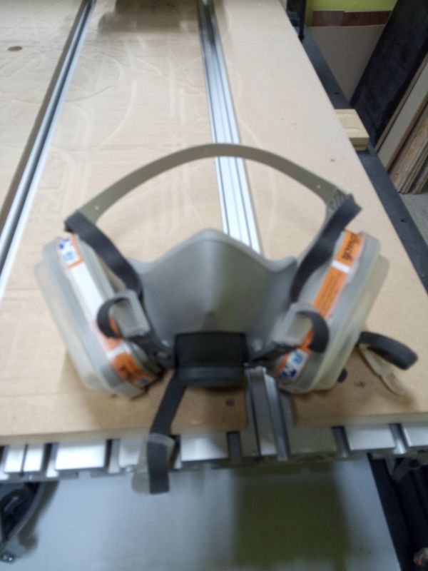
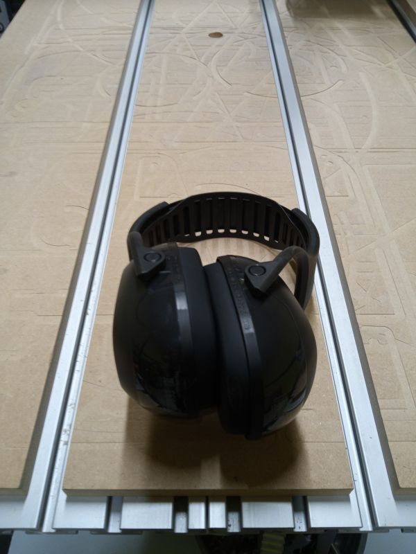
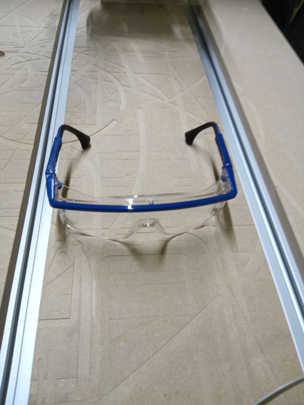
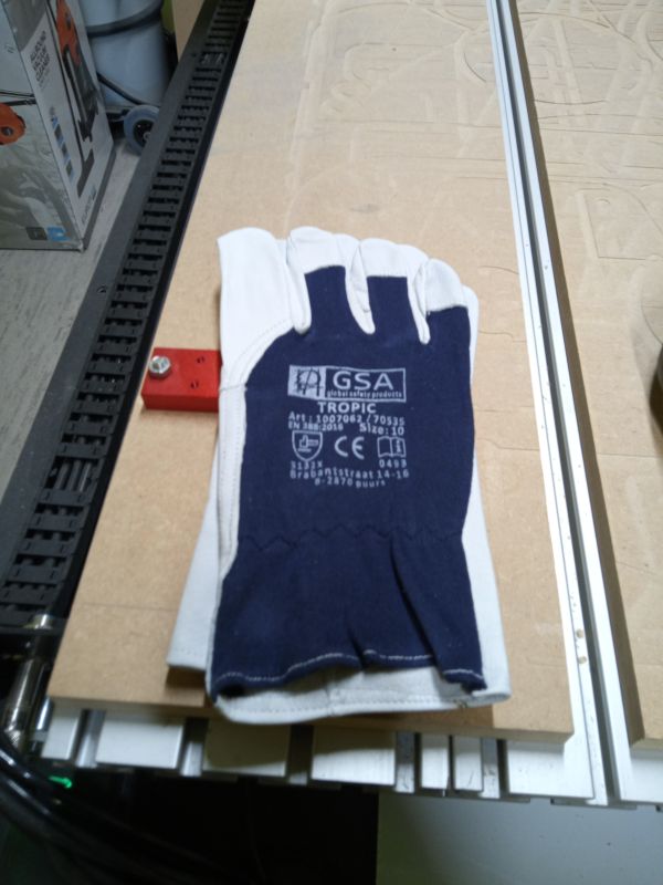
Human protection
Safety is essential in the fablab (even more so with this kind of machine). The first step is to have personal protective equipment (e.g. ear muffs, goggles, dust mask, and gloves especially for moving the boards)
Starting the machine and security
at the fablab, we decided to put the machine in a secure place (in a room with only one entrance where it is alone).
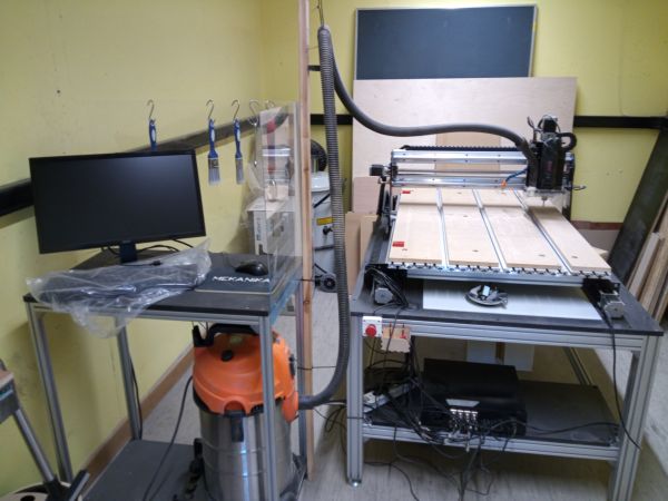
We are using a Mekanika Pro-M Mk1 Link
Mekanika uses PlanetCNC software running on a Raspberry Pi 3
Mekanika is a Belgian startup that creates completely open source and scalable machines. Here is the link to their website : https://www.mekanika.io/

Presentation of the ensemble. On the left, the console part, on the right the machine.
A bit of advertising
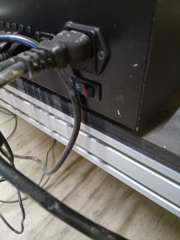
First, turn on the power strip
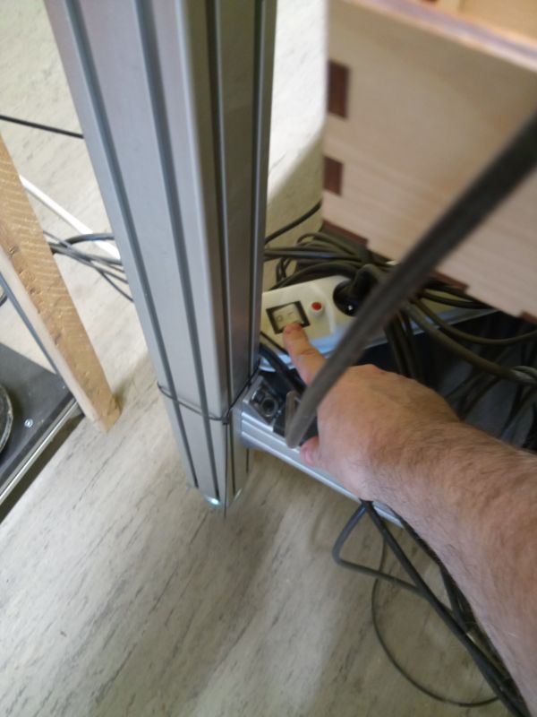
The Raspberry Pi starts up.
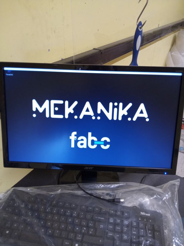
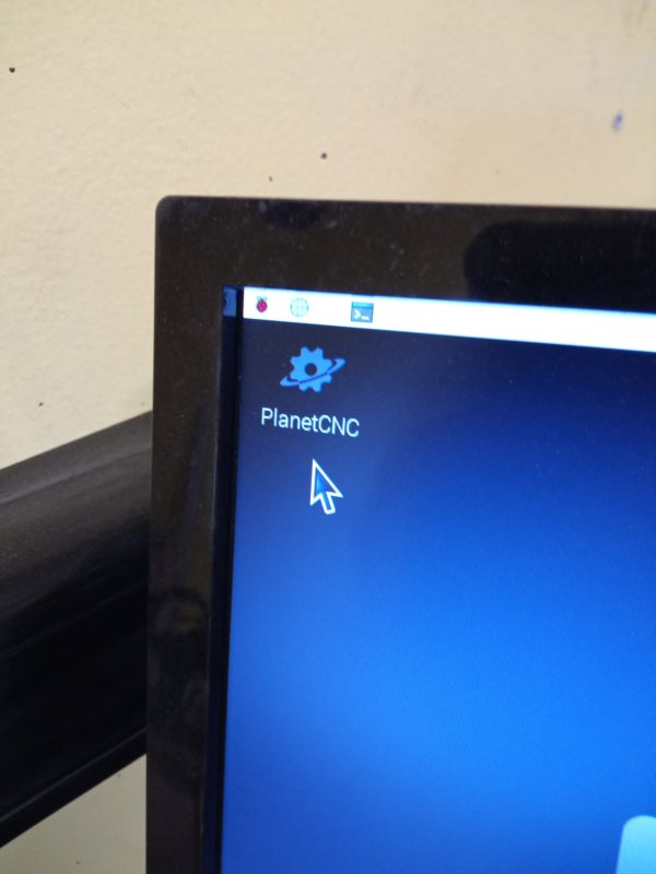
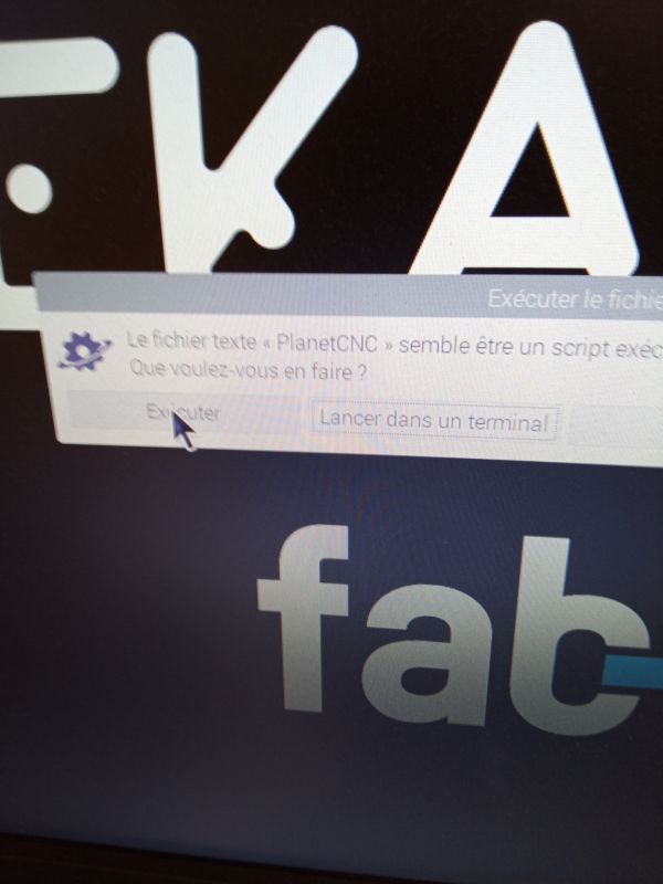
You can start PlanetCNC
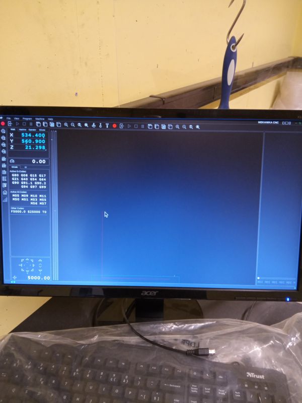
Now we can start the machine
Warning
Make sure there is nothing in the way of the machine
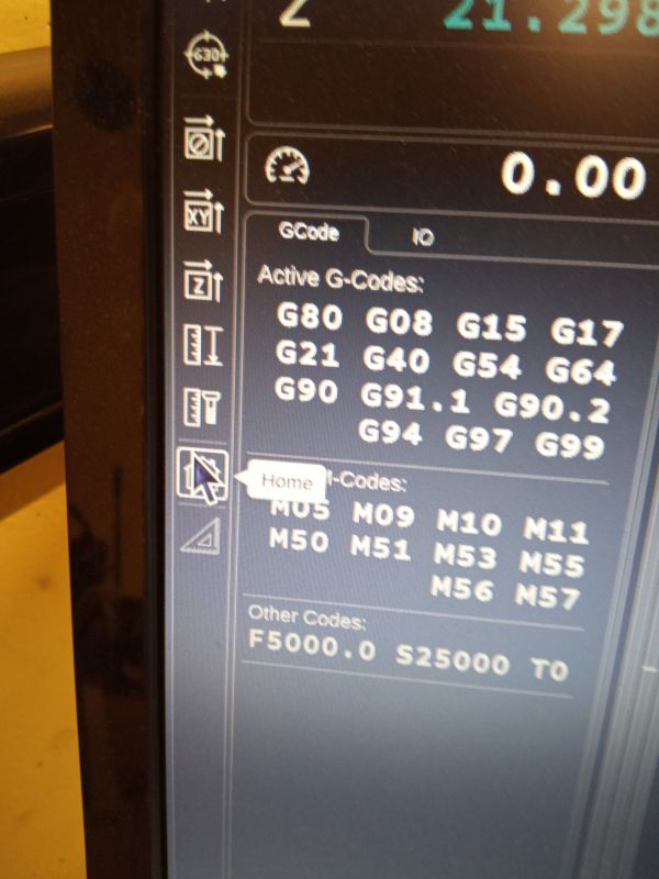
You can click on Home. The machine will move in X, Y and Z to then position itself at its home
Warning
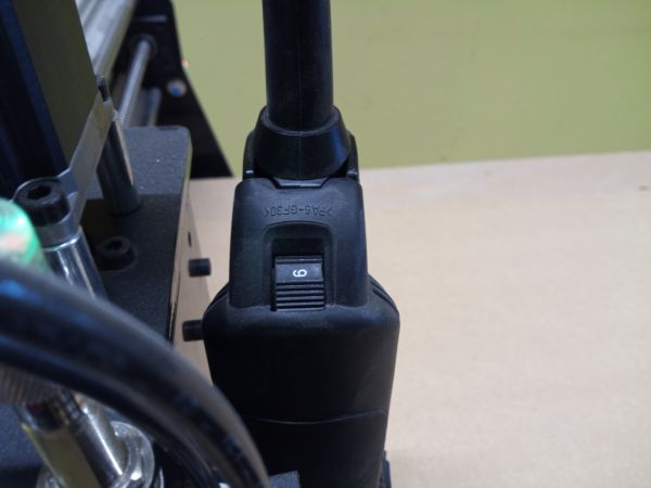
To change the tool, disconnect the spindle
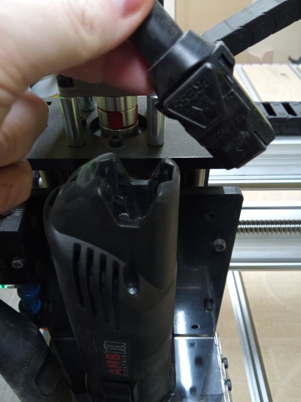
When the tool is changed, you reconnect the spindle
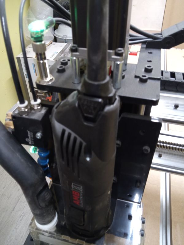
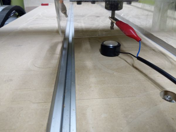
We are going to move the spindle to be able to adjust the Z axis
Warning
Have your hand next to the emergency stop
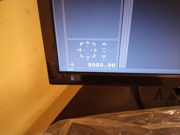
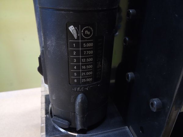
Setup Speed Spindle
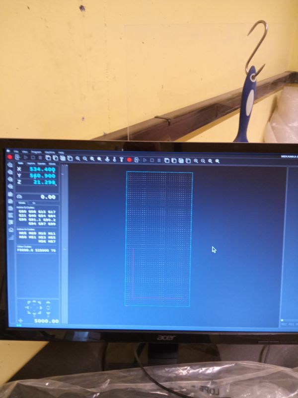
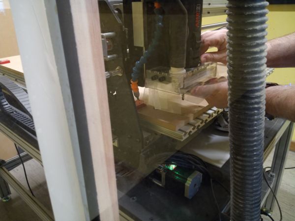
The next step is to do an empty test without putting on our work board.
We load our file for testing and run the job empty to see if everything goes well. (I remind you to have your hand on the emergency stop button just in case)
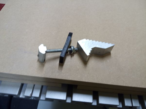
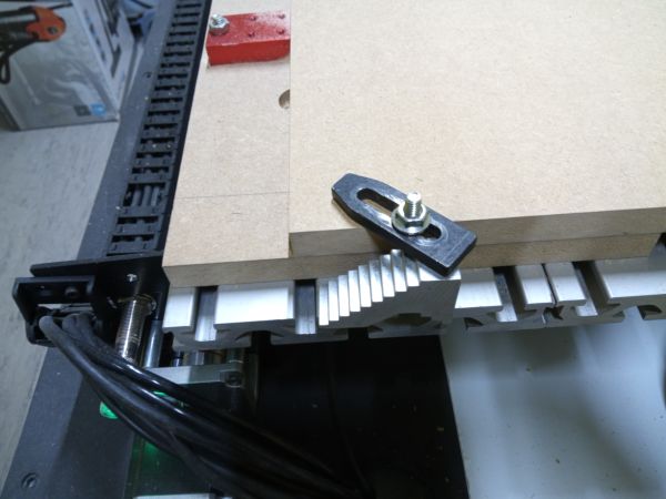
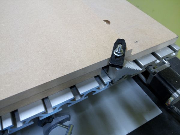
We can install our work board and fix it with the clamps
Warning
Ensure that these are not in the way of our tool
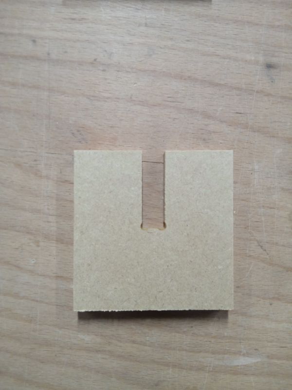
testing
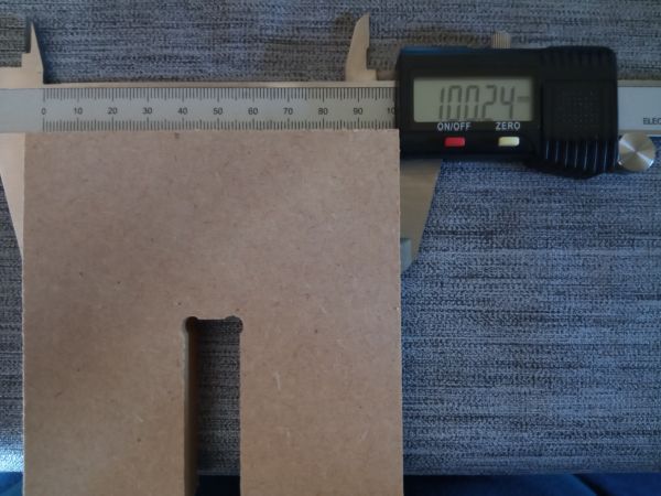
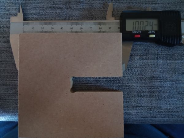
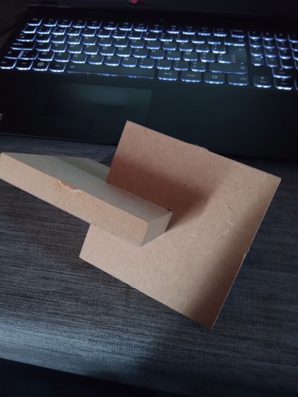
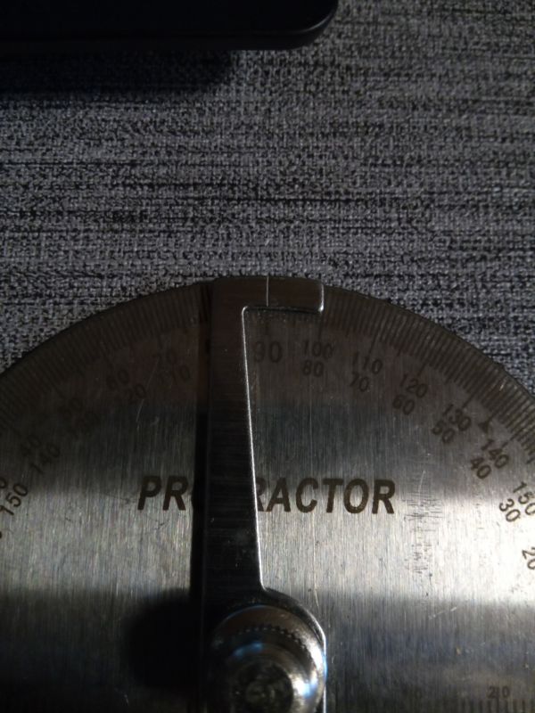
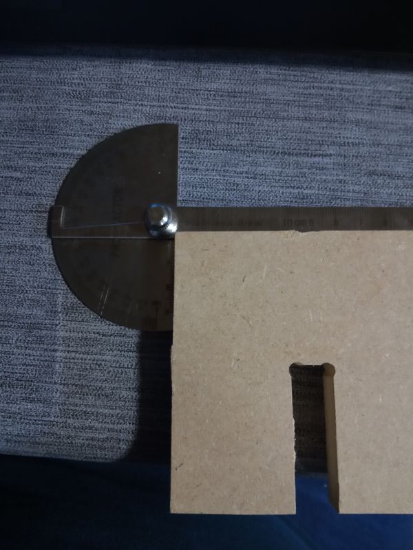
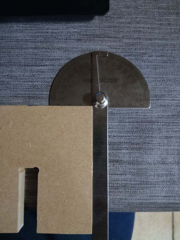
I made a design to test the dimensions and angles of the machine, as well as the clamping joints (without glue)
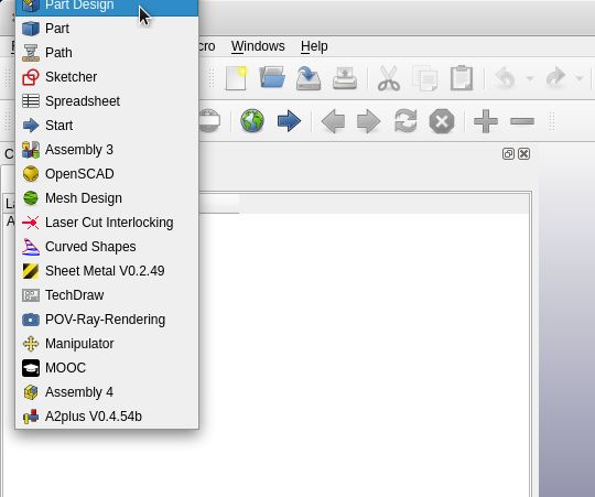
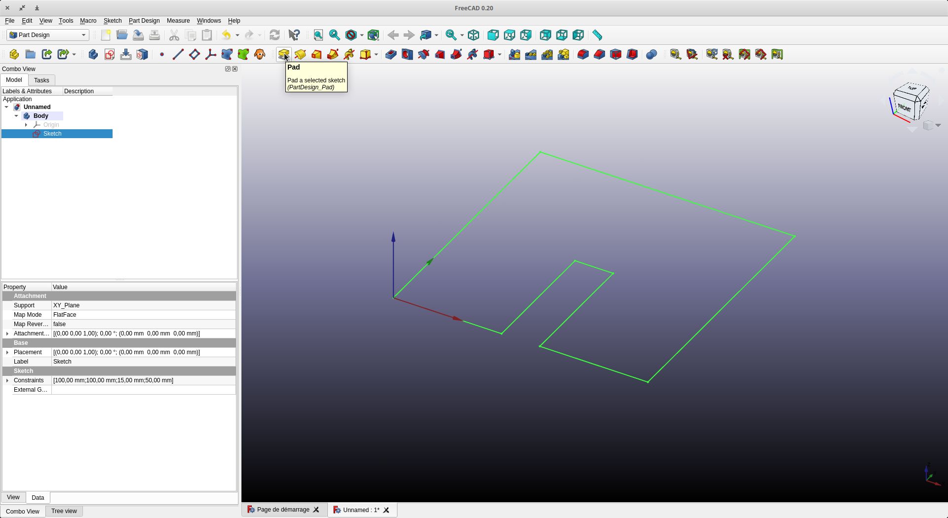
We start Freecad and open a new document. We go to the Part Design workshop and create a new sketch
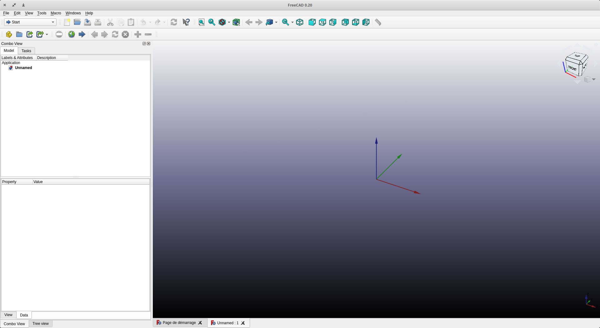
Select workbench “PartDesign”
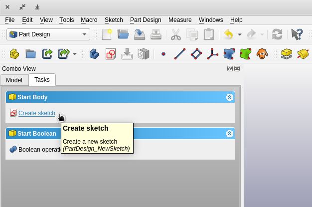
Create Body
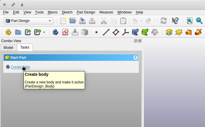
Create sketch
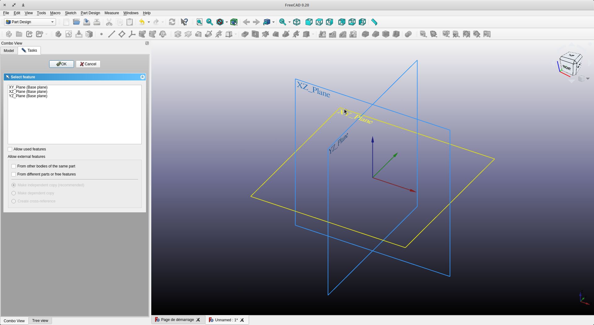
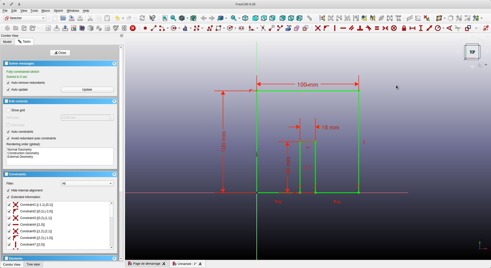
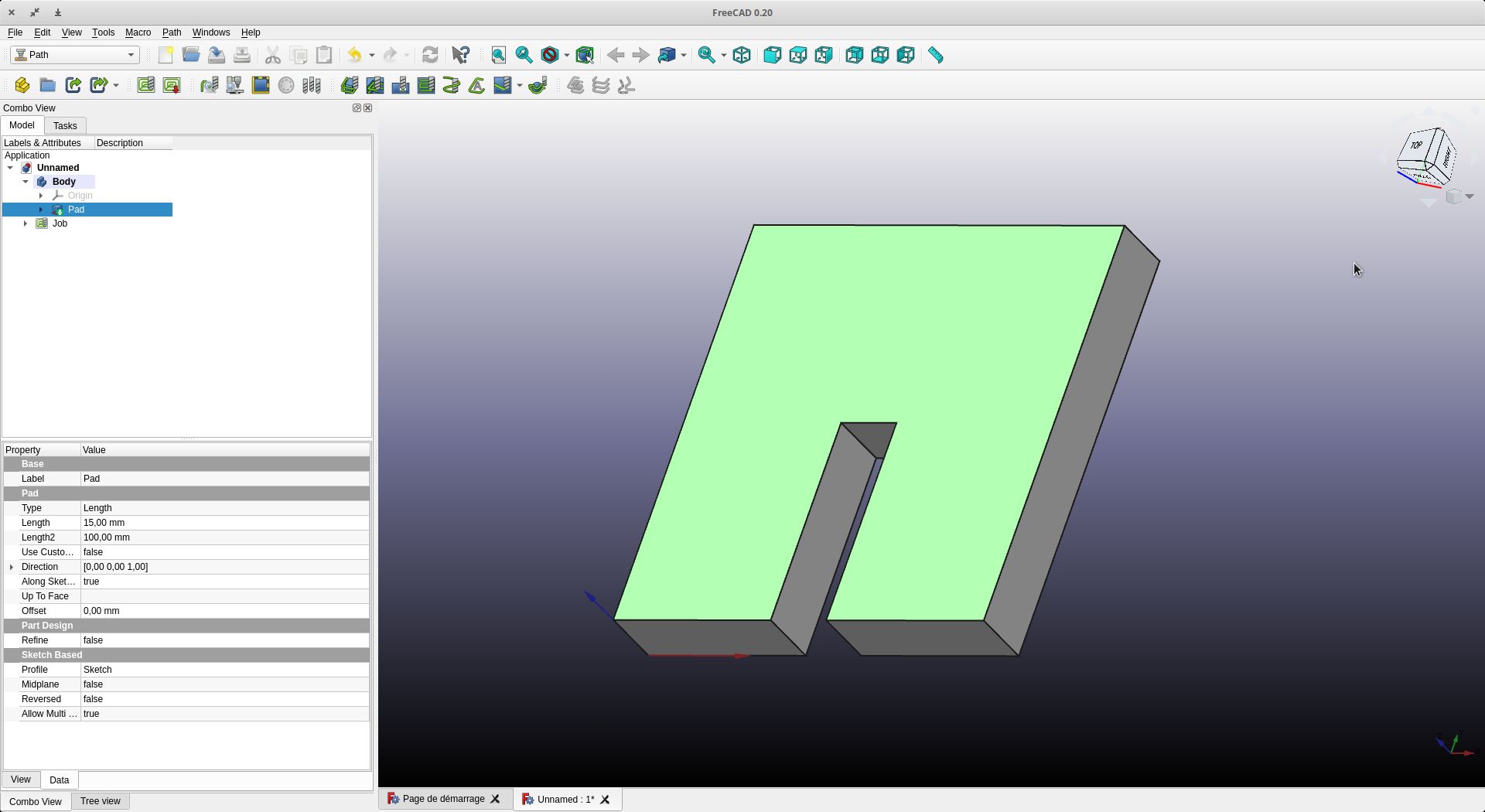
We choose a plan and start drawing the sketch. Here a square with an interlocking
Draw your sketch
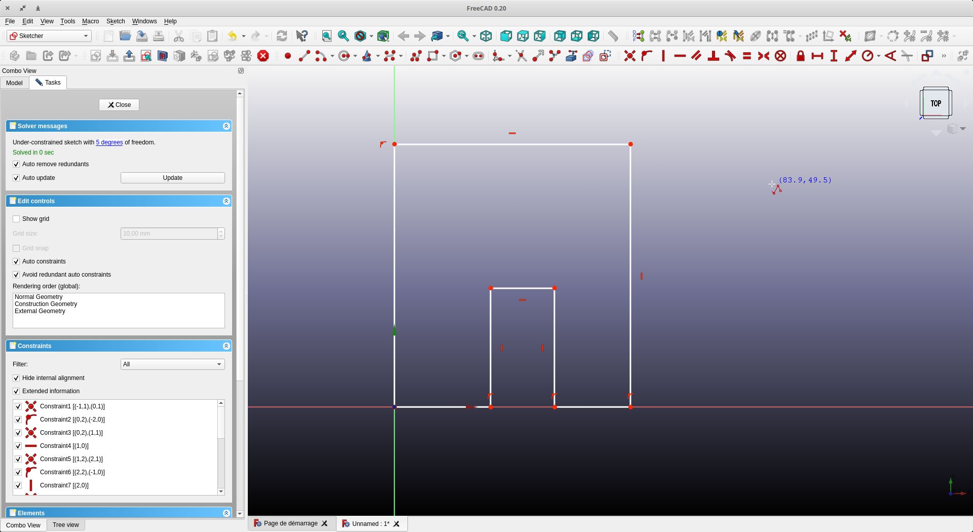
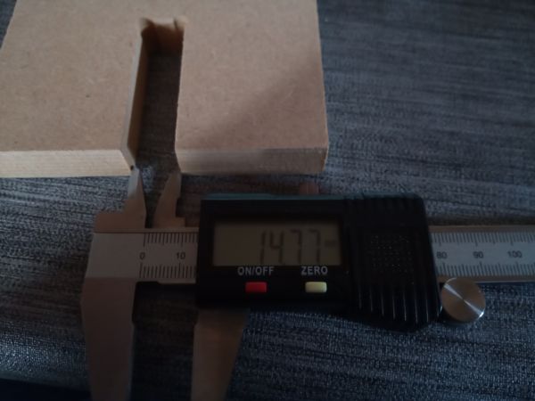
The dimensions are given - 100mm for each side. For the interlocking, a depth of 50mm and a spacing of 15mm is used (15mm thick MDF board is used)
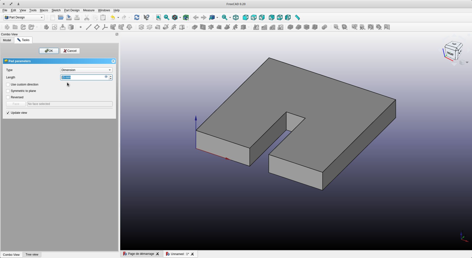
We close and make a 15 mm extrusion (equal to our board thickness)
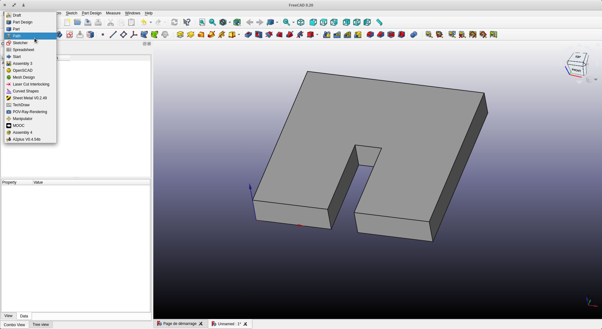
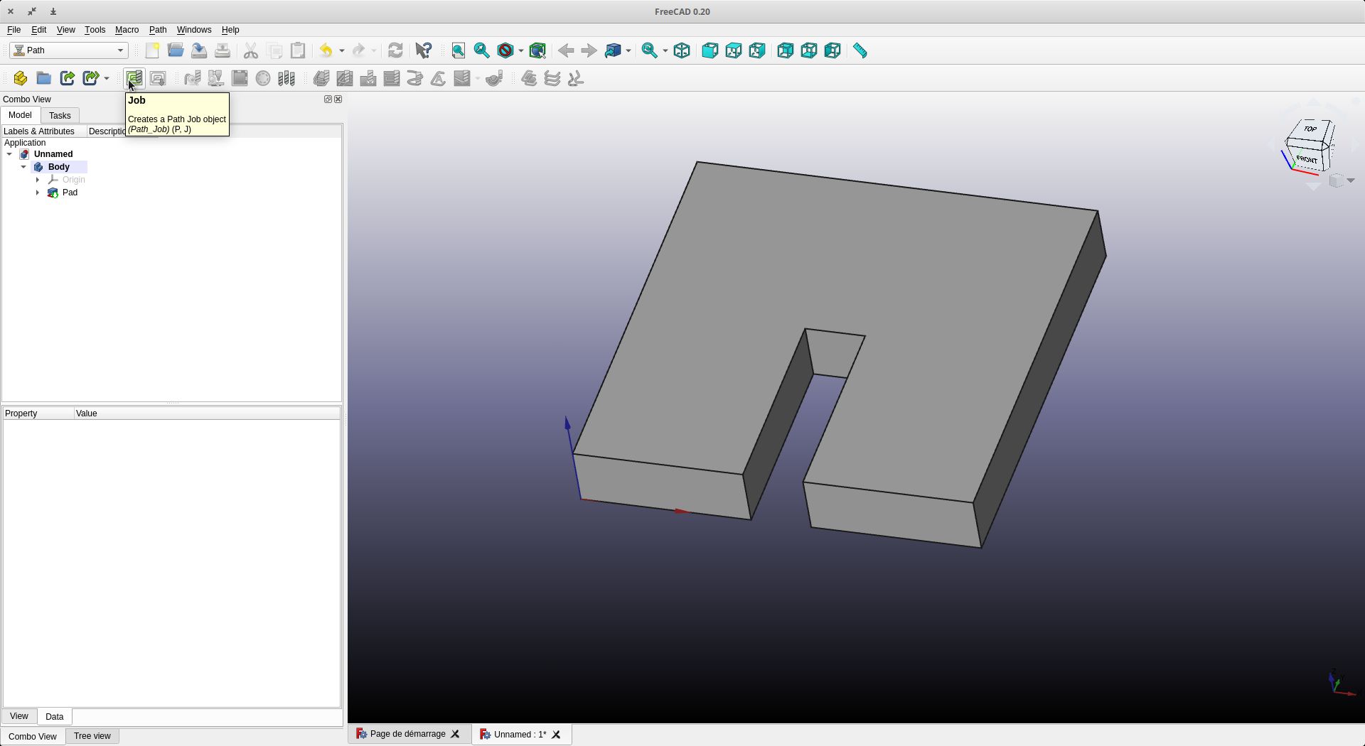
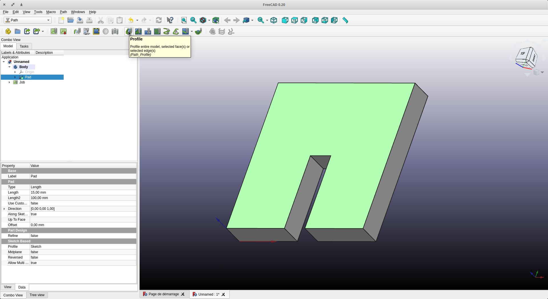
Let’s go now to the “Path” workshop
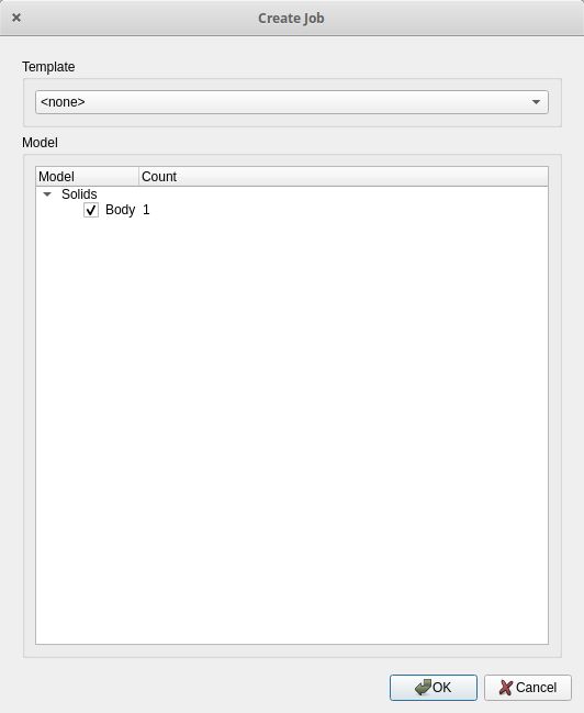
Click on job
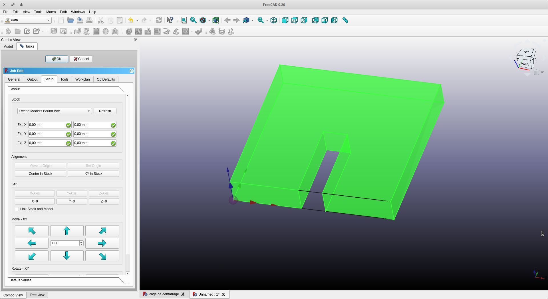
We check that ext X, Y and Z encompass our object and that we are in the right direction, especially for Z
Let’s go to the tools tab
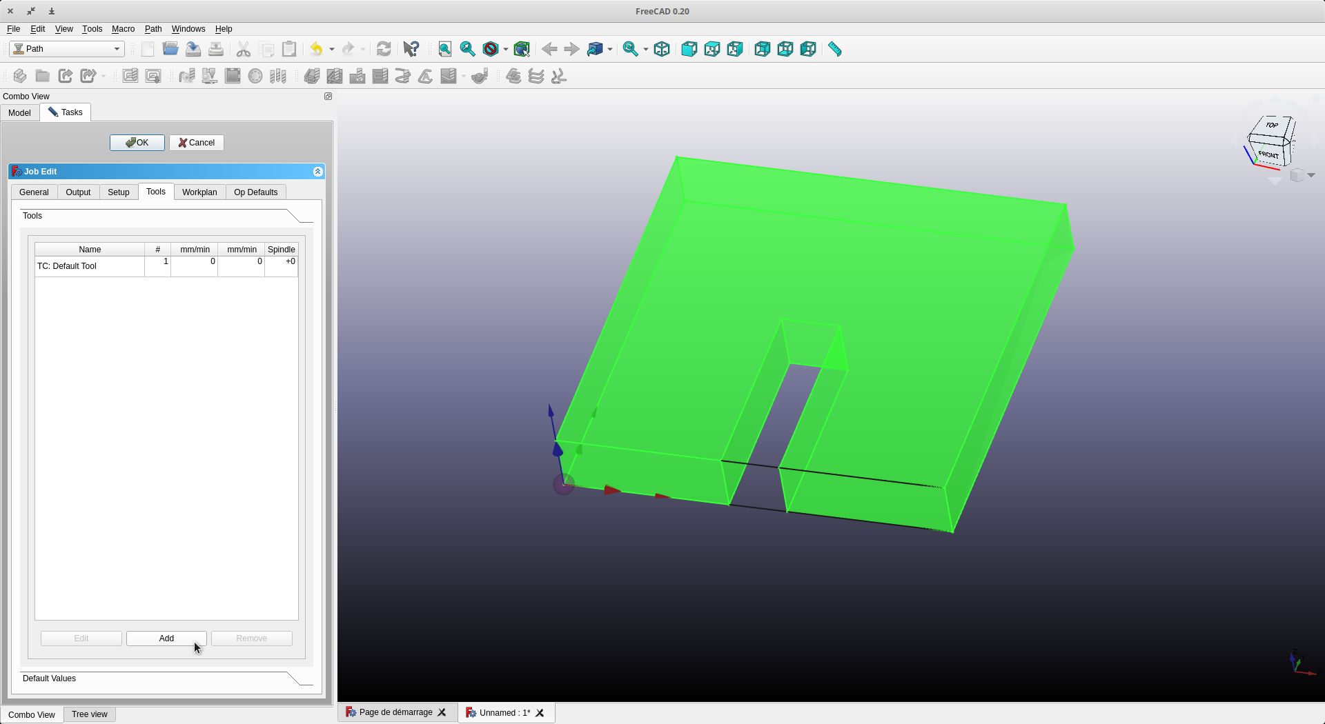
We will add or create a tool
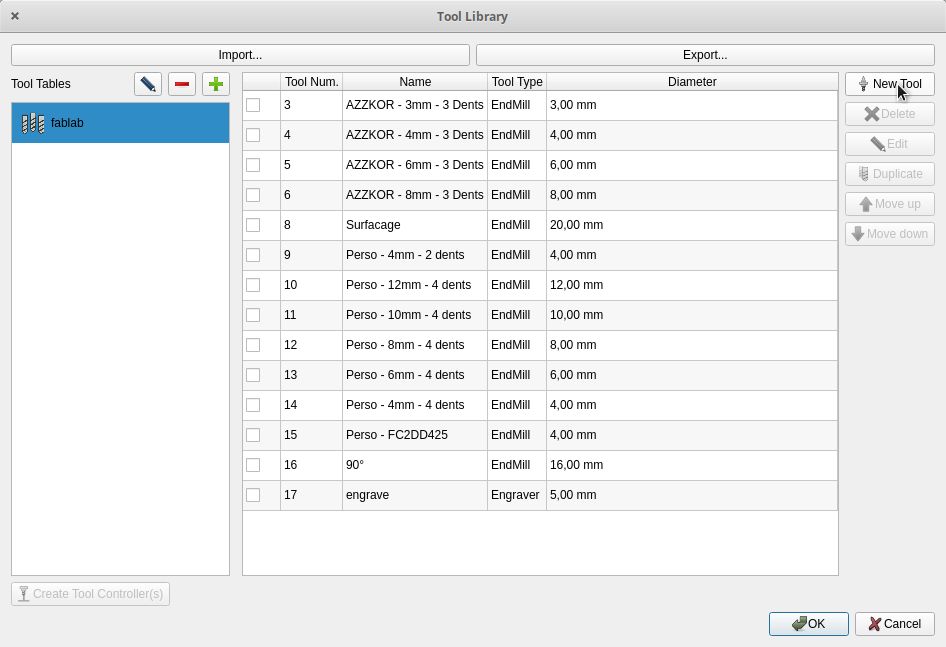
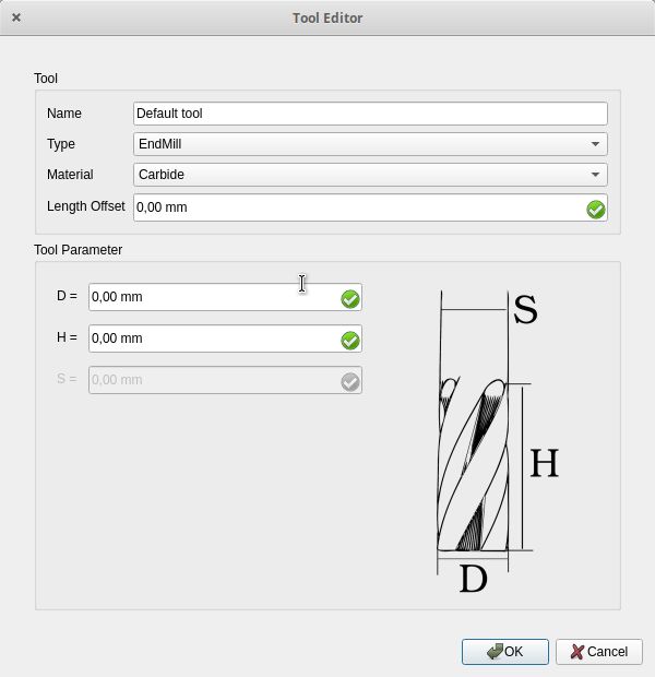
If it does not exist, click on “New Tool”. Enter the different information of the tool.
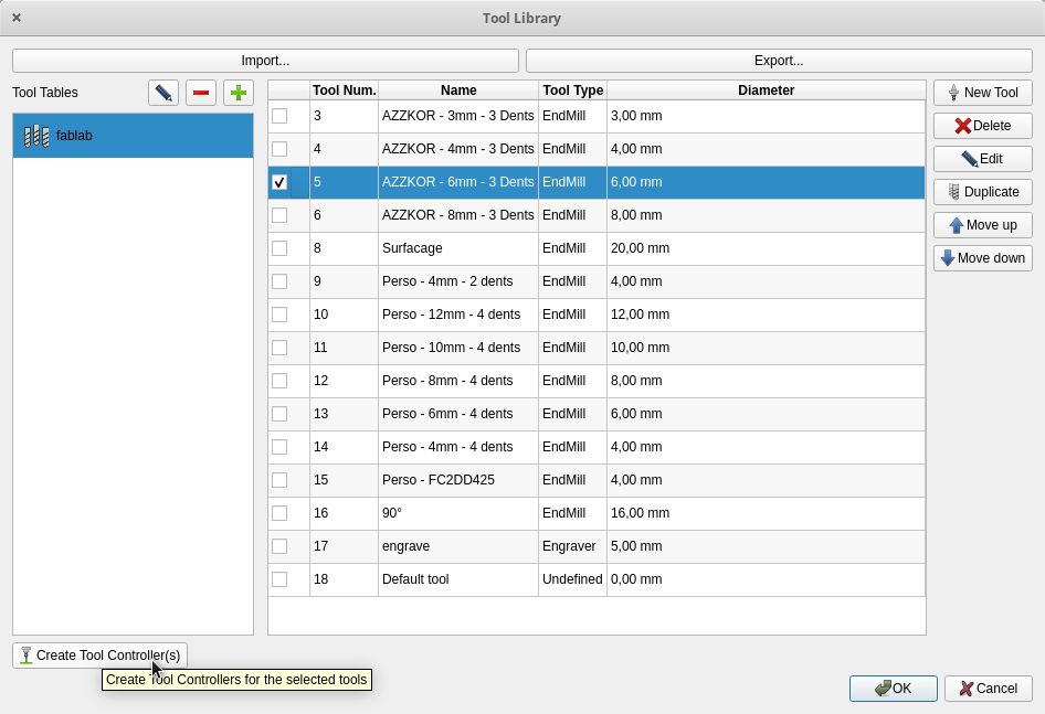
Once everything is done, select the tool you wish to use and click on “Create Tool Controller”.
Don’t forget to put on your gears. I have calculated them via my calculator (CNC-Calculator ) which gives the maximum speeds. With a bit of experience, I do different tests as the work progresses to increase the speeds little by little. For the moment I am at 2000 mm/min for the speed of movement. For the spindle speed I stay around 25000 RPM


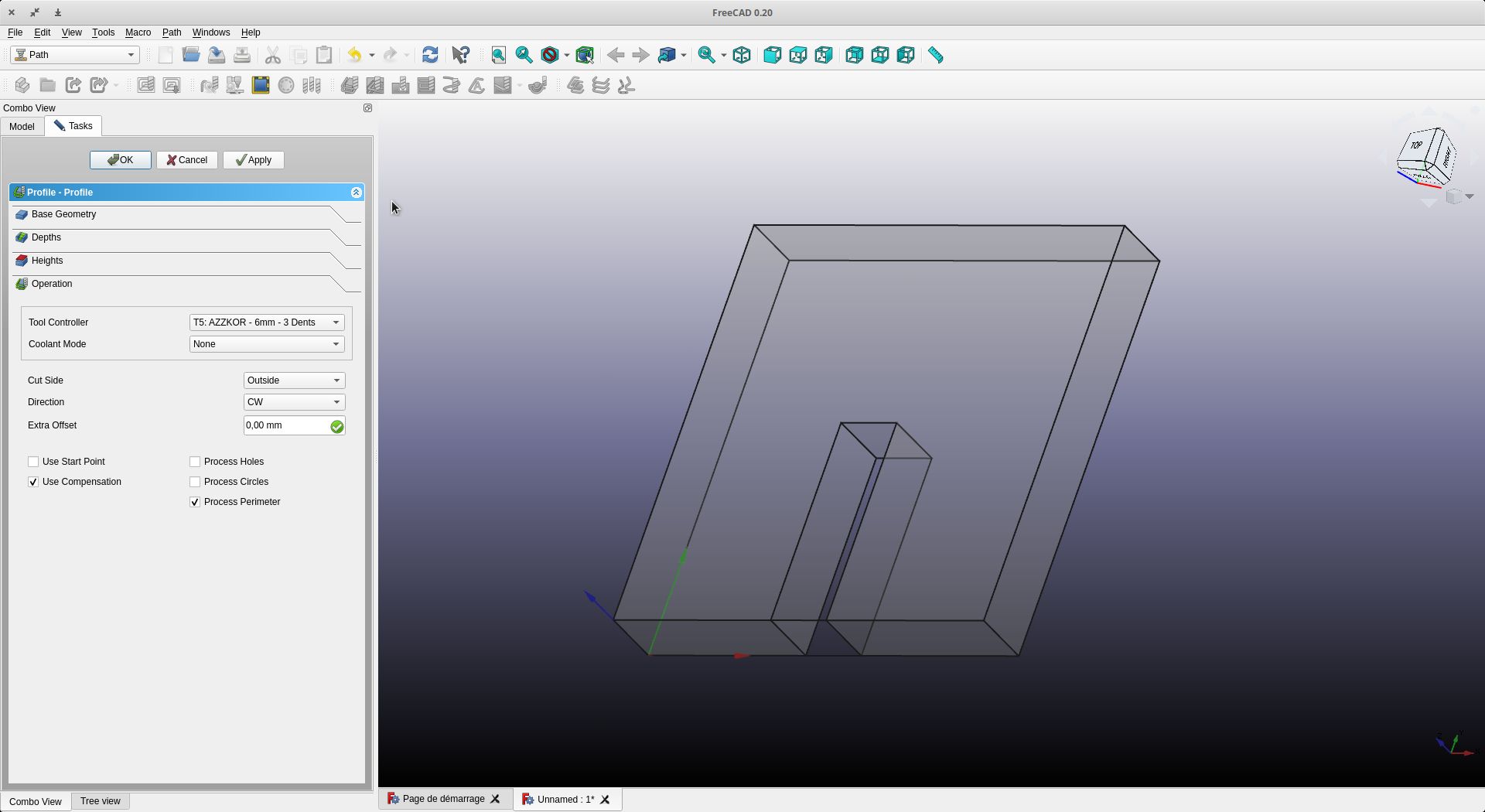
Click on Profile to do the cutting job
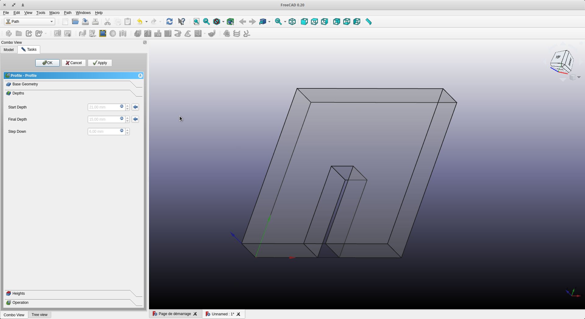
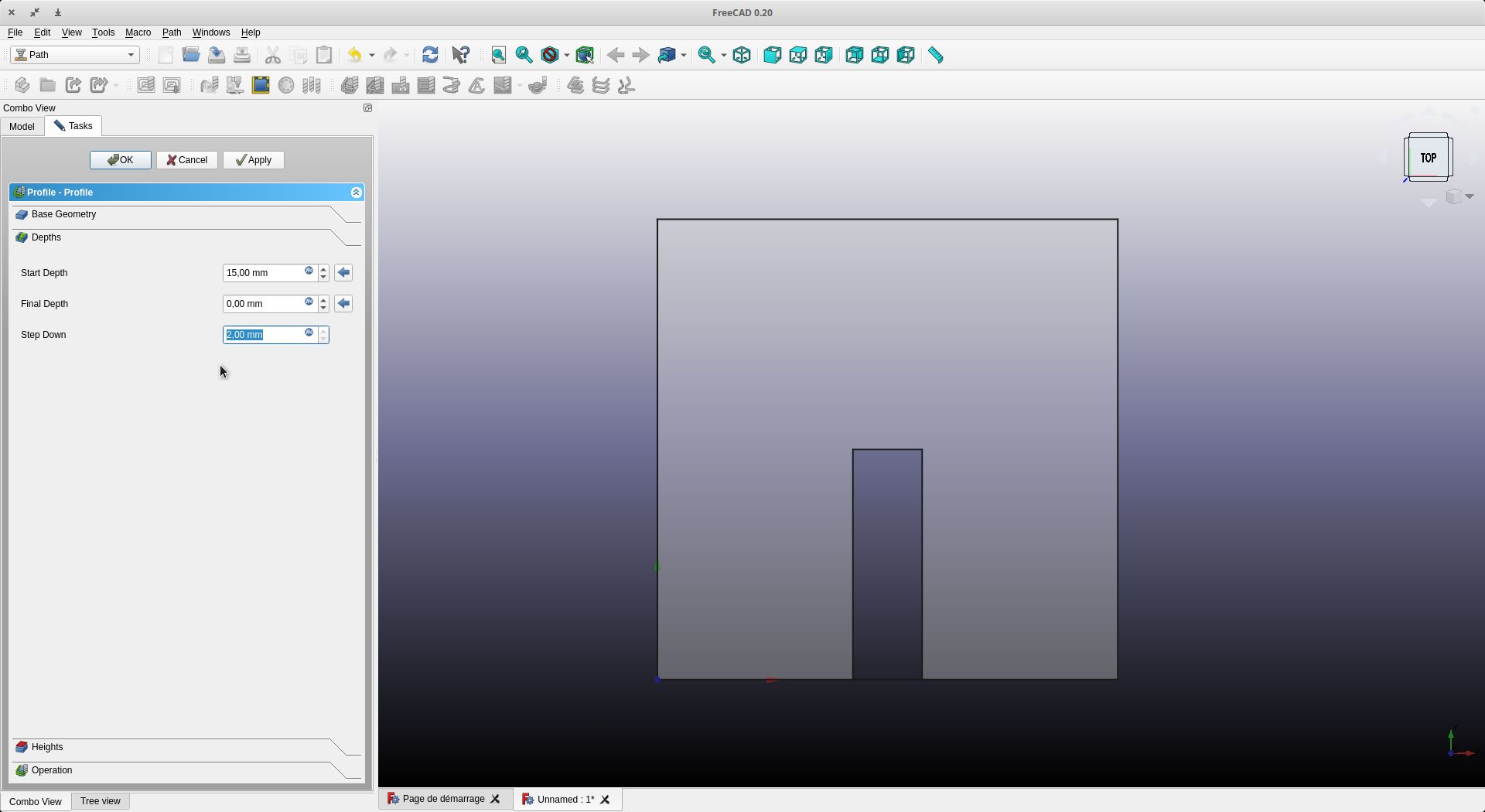
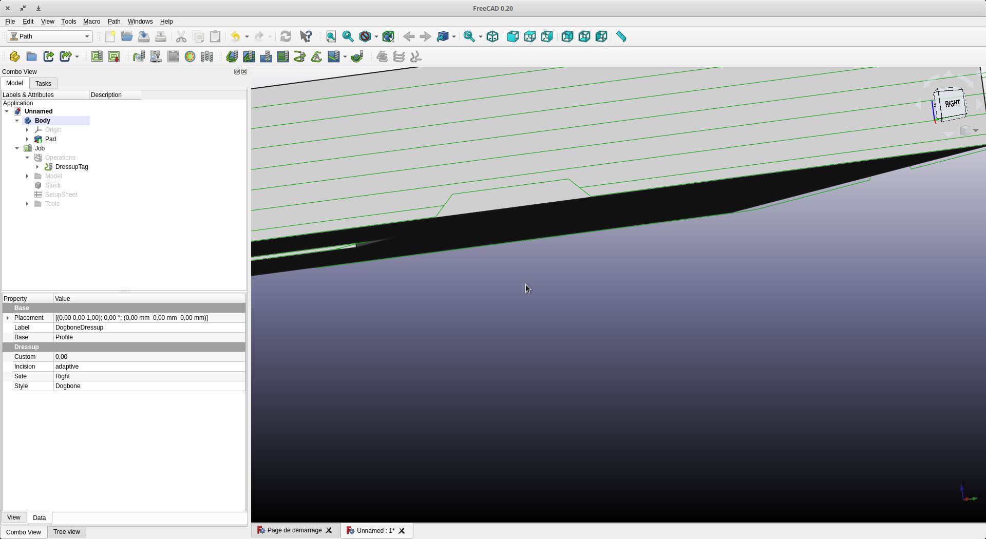
Check the height parameters (start and end) and the descent pitch of the spindle (here I am using 2 mm steps)
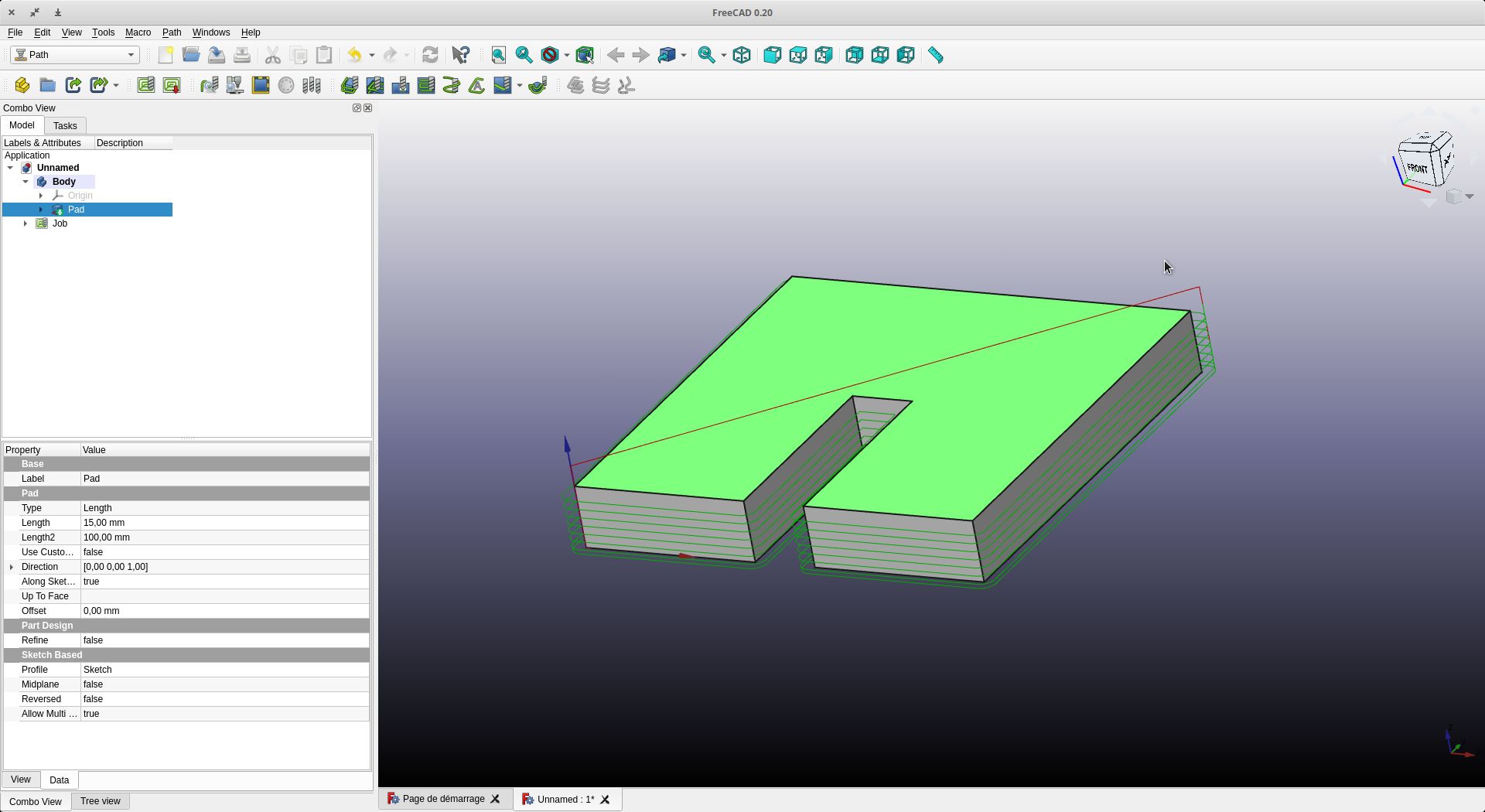
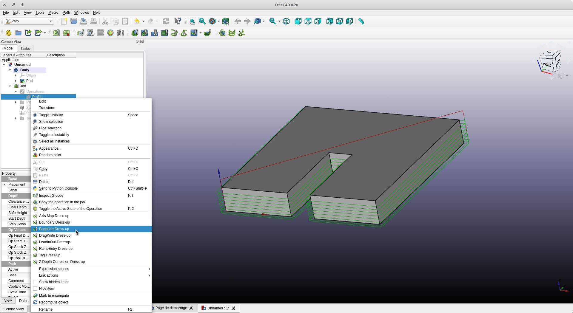
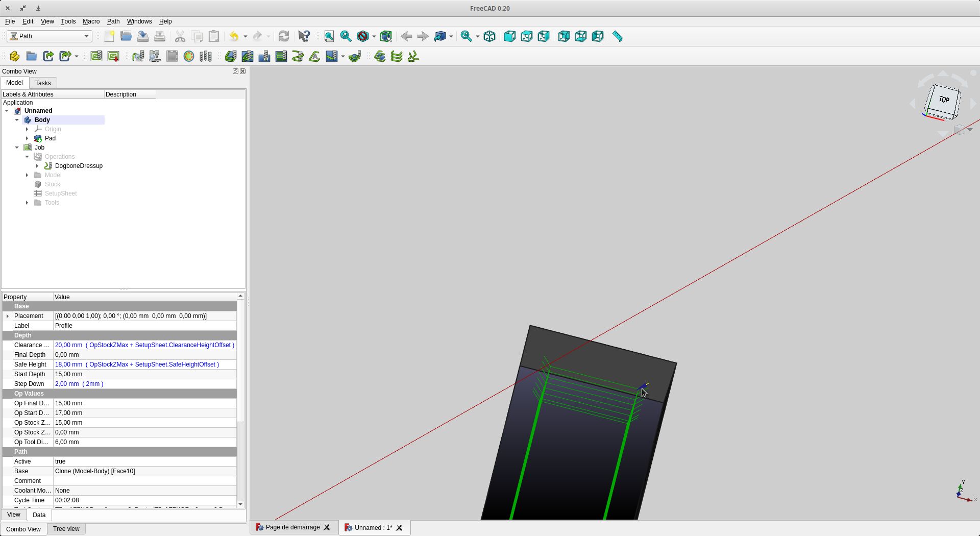
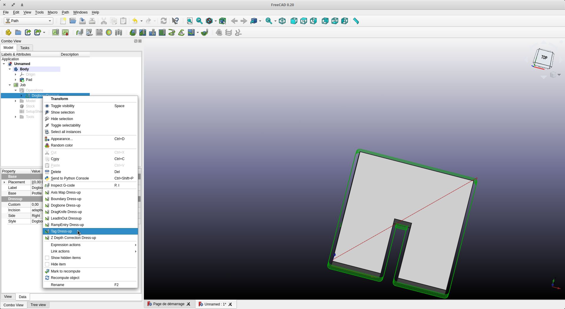
You can see the traces of the tool’s passage. We will make dogbones.
Info Dogbones
Dogbones are a great way to allow vertical plates to be inserted into horizontal plates without out having to worry about the radius left from the cutter. Depending on the thickness and size of the part will affect the size of the dogbones needed. When possible, its best to use a 0,8mm radius as this will help keep the machine time down. A small cutter such as a 0.5mm radius can be used but it will take more passes and a slower cut rate, which will increase the cost of the parts. If you wish to not use dogbones when making slots for a vertical plate, you can also ensure that you get a better fit by making the slot longer then needed to allow for the radius of the inside corners. This may make the part a bit more loose in the slot.
Types of dog bones
 This is the most common dogbone used. It’s great as it gets the radius of the cutter outside of the slot to allow a good fitment of the parts. The only issue is if the slot is close to an outside edge or another hole, it can get a bit too close as it requires a bit more room.
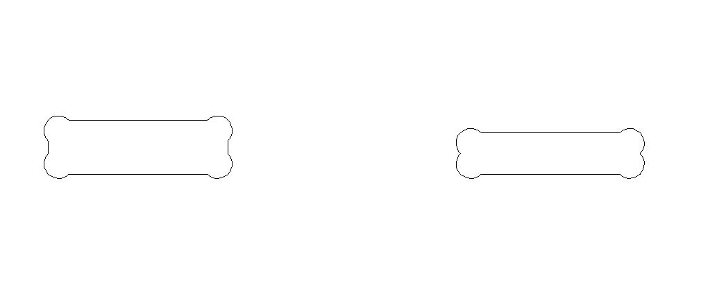 Here is a great alternative to the above dogbone. It works well when there is less romme but it have one downside. On narrow slots, the material remaining at the ends of the slot are very small and may not hold properly. This is more suited for wider slots where more material can be left behind to hold the part.
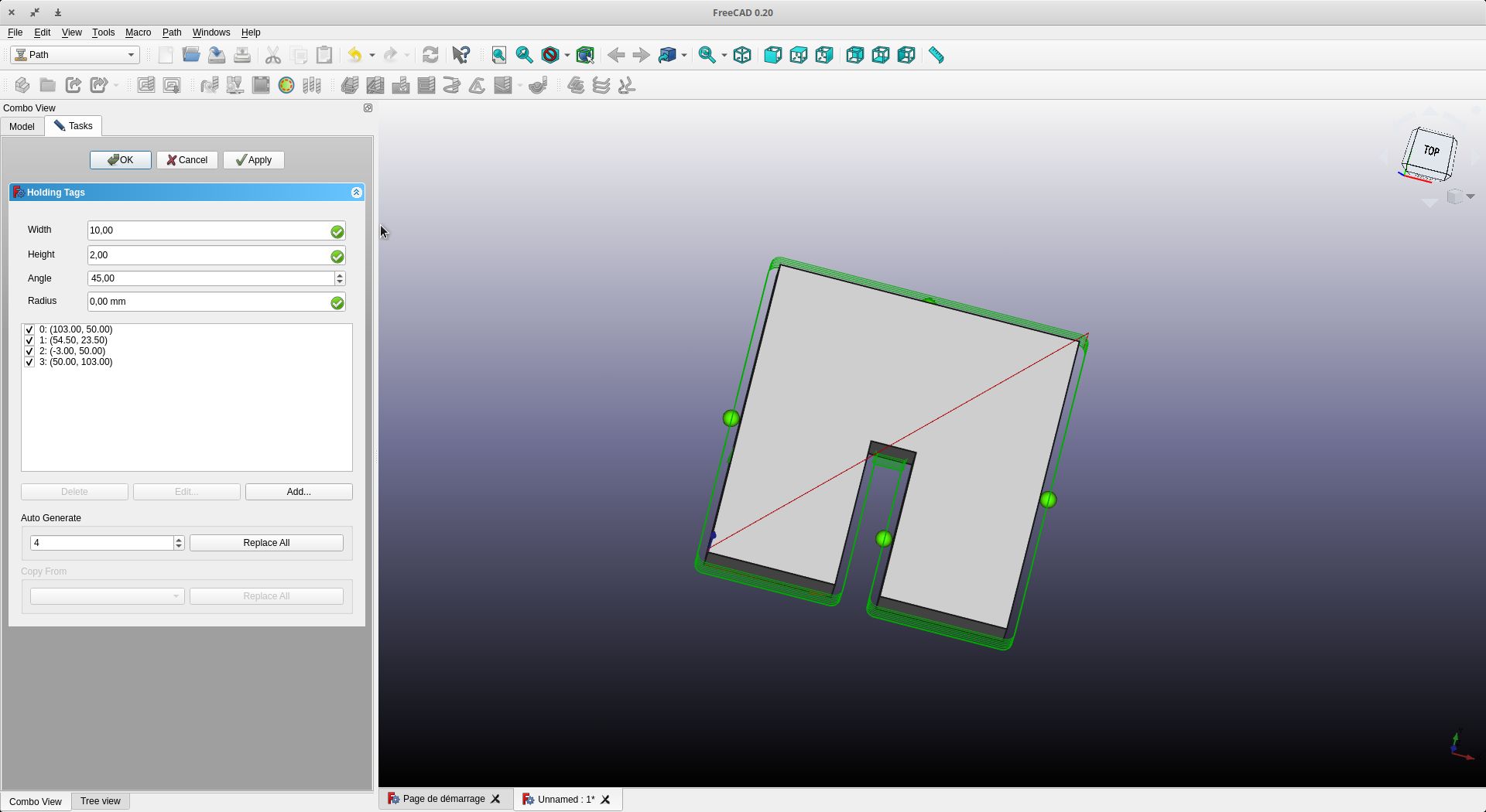
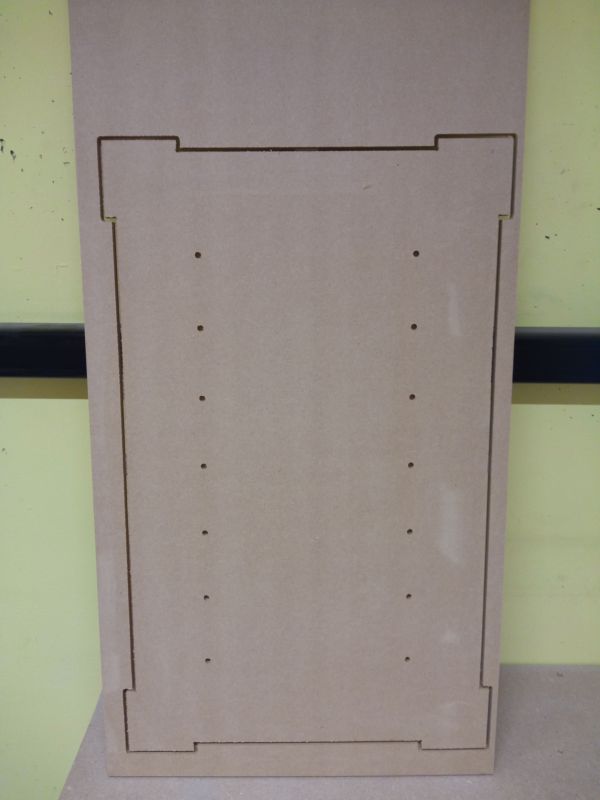
We add holding tabs for safety and to ensure that our board will not move at the end of the job
The dimensions of the retaining tabs can be changed. Personally, I use a length of 10 mm and a thickness of 2 mm for the MDF

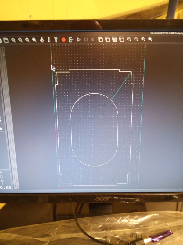
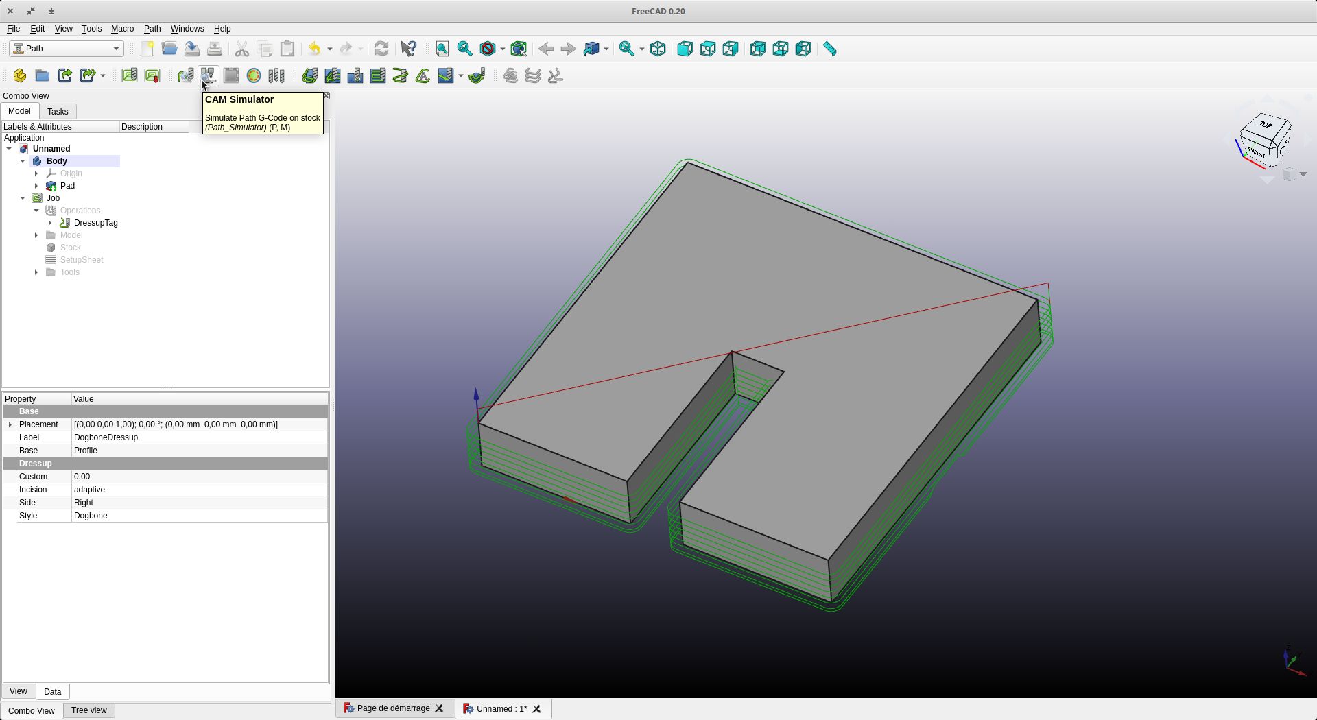
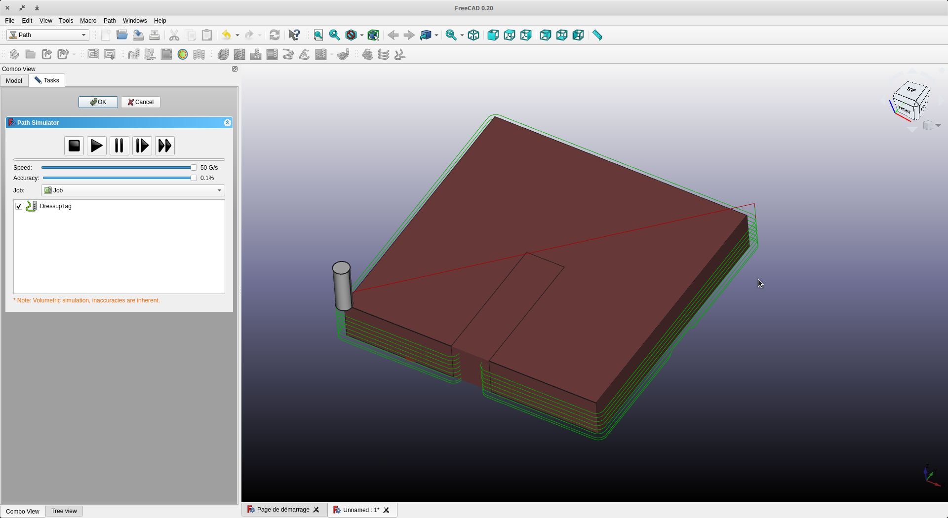
Once we have done all these operations, we can simulate the work by clicking on “CAM Simulator”.
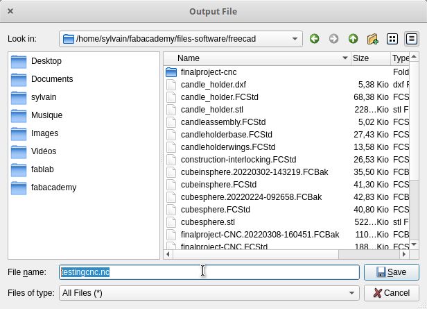
We can now save our file to be read by our digital milling machine. First of all, we have to choose the post-processor (in our case Linuxcnc)
We click on Post-Process and we can save our file with the extension .nc

Results :
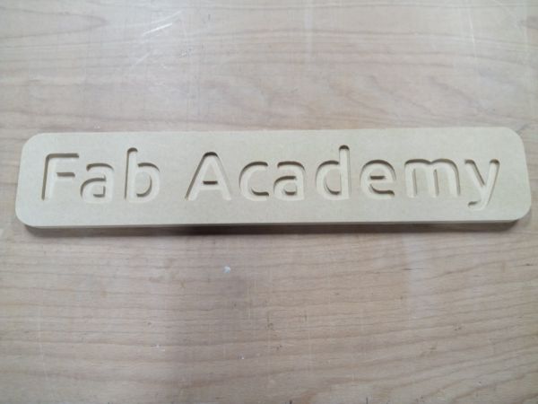
I also made an engraving and cutting. Here is the result. For the Fab Academy registration, I used the “pocket” operation. To do this, the thickness of the letters must be greater than the wick used.
Files :
Individual assignment
Module 3 of Final Project
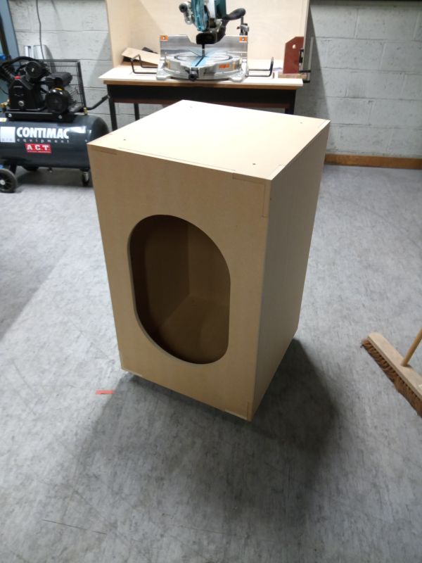
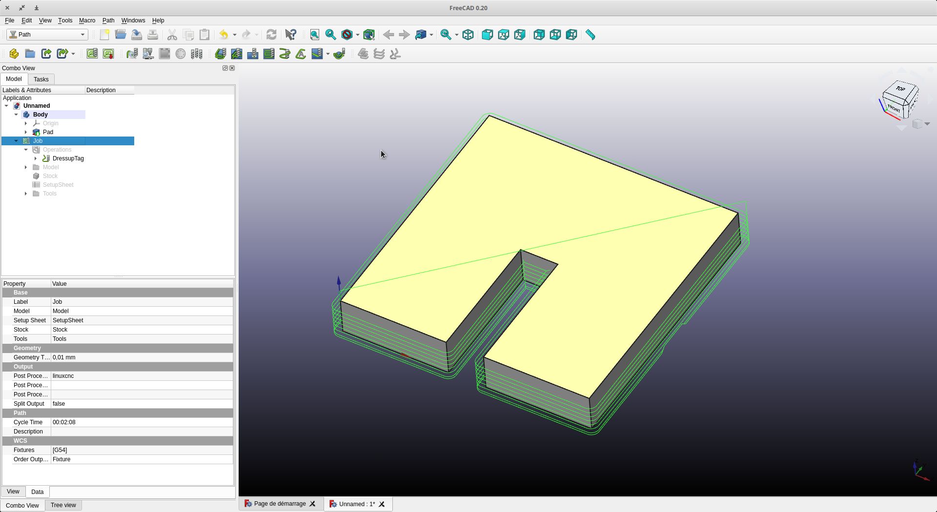
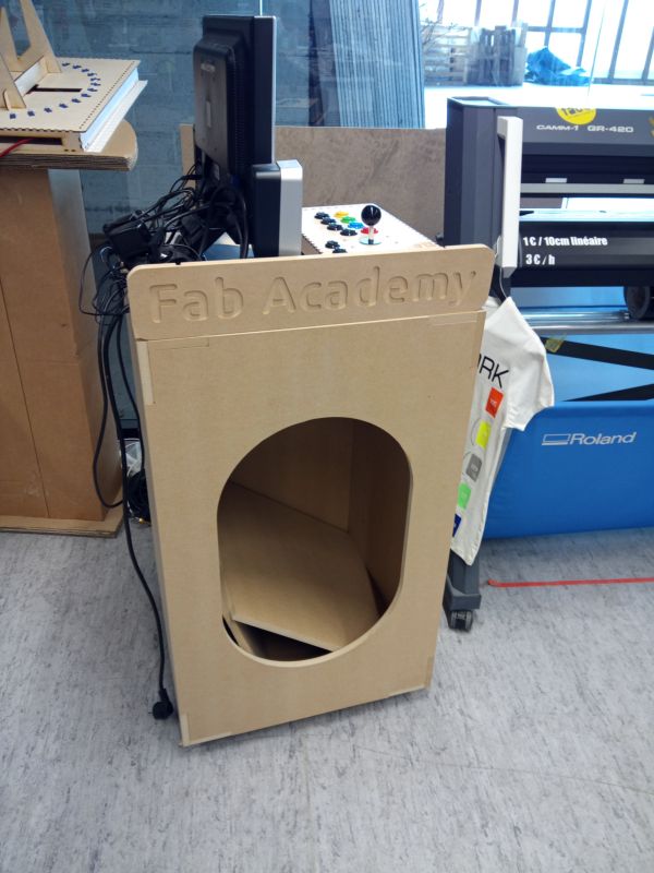
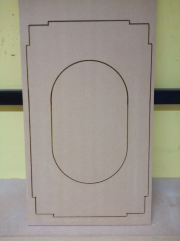
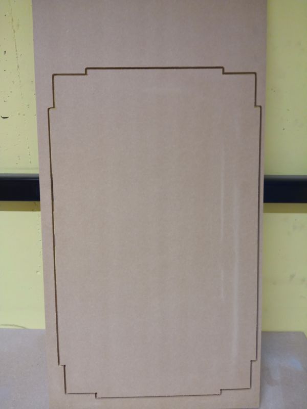
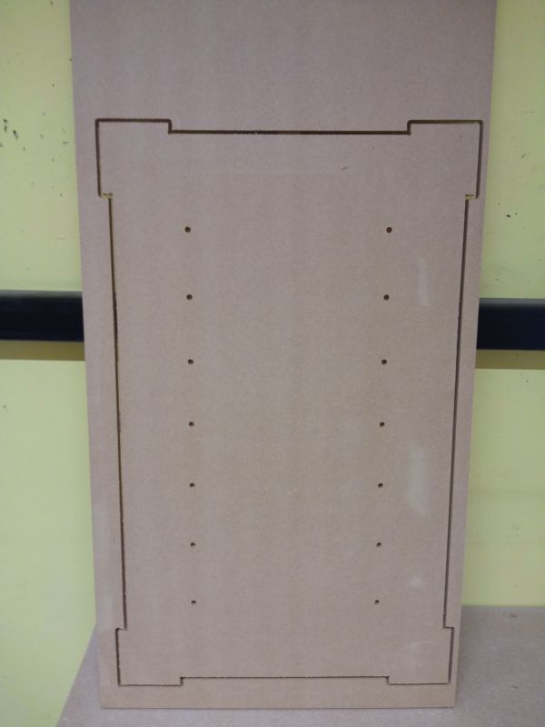
For my individual work, I took the opportunity to do some of my final work. This is a part of the furniture of my project here in brown.
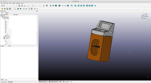
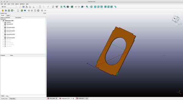
To simplify the task, I have duplicated my work so that I only have the digital milling work on one file. This also makes the original file safe and prevents having too big a construction tree.
You can download both files and the gcode files below
- finalproject.FCStd
- finalproject-CNC.FCStd
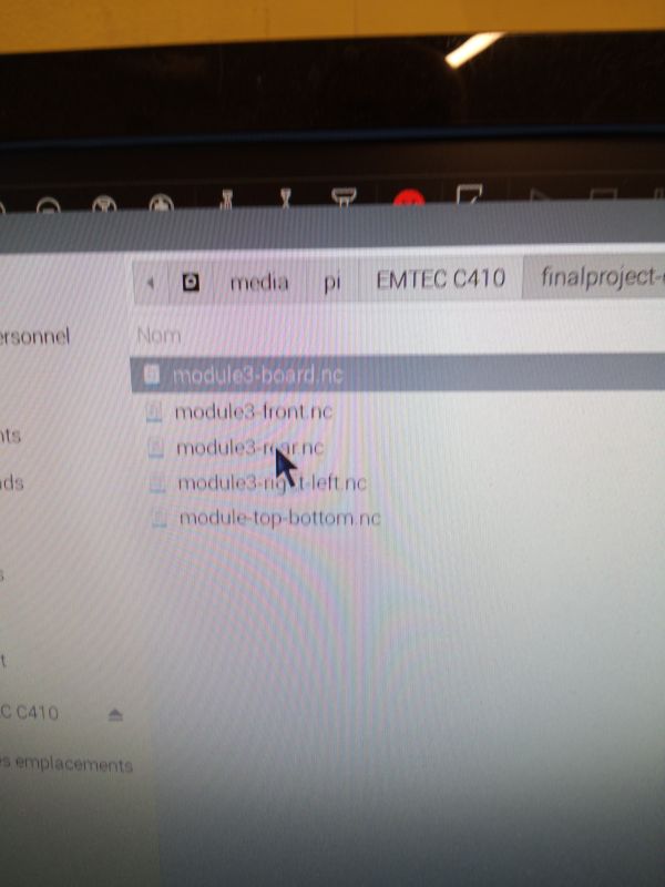
- module3-board.nc
- module3-front.nc
- module3-rear.nc
- module3-right-left.nc
- module3-top-bottom.nc
Video of 1st piece
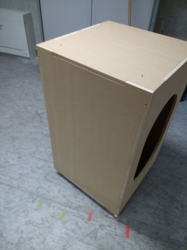
We’re off to cut. All in all, I had two hours to do it
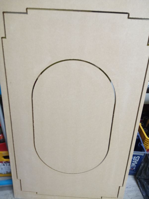
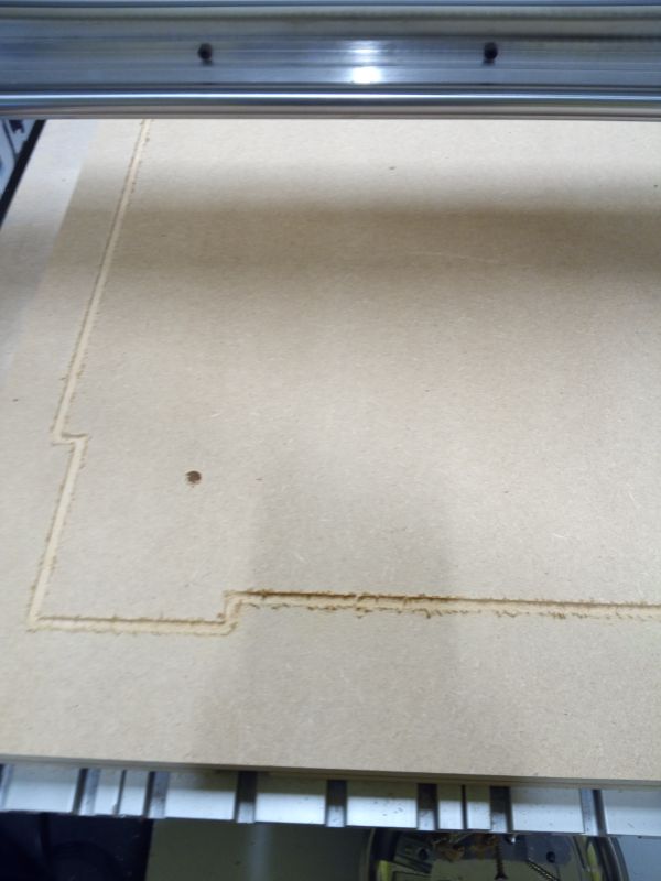
Cutting out the retaining tabs
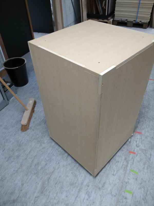
A little sanding
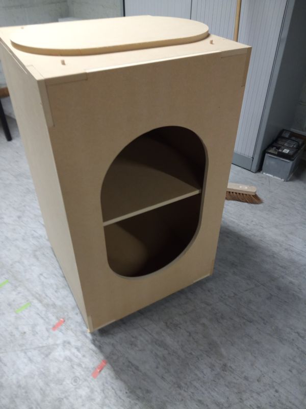
Final Result