14. Networking and communications
Individual assignment :
- design, build, and connect wired or wireless node(s) with network or bus addresses
Group assignment :
- send a message between two projects
Individual assignment
This week we will use an ESP32 Board.
This week we will be using an ESP32 Board. To do this we need to install the recognition of this board in the Arduino IDE
Installing the ESP32 Board in Arduino IDE
Prerequisites
Arduino IDE Installed
To install the ESP32 board in your Arduino IDE, follow these next instructions:
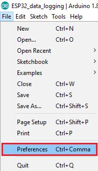
1 . In your Arduino IDE, go to File> Preferences
2 . Enter the following into the “Additional Board Manager URLs” field:
https://raw.githubusercontent.com/espressif/arduino-esp32/gh-pages/package_esp32_index.json
Then, click the “OK” button:
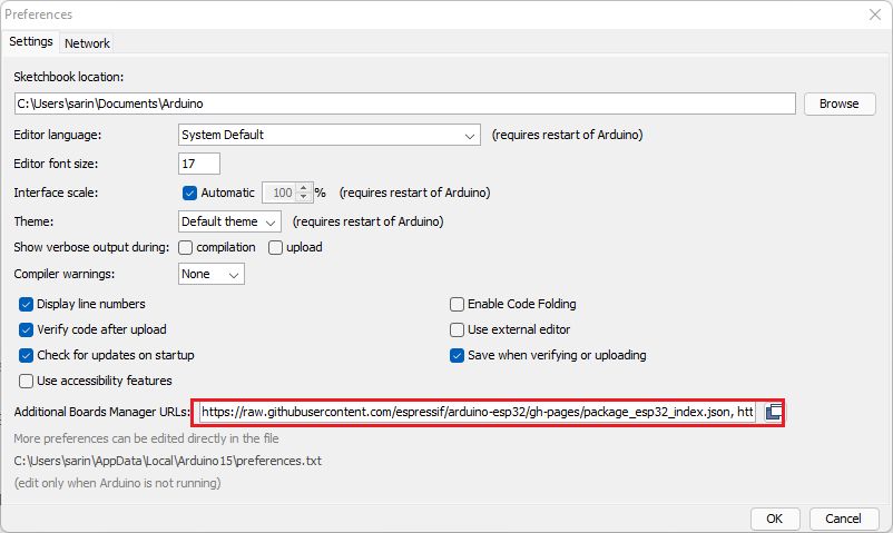
if you already have other links, you can add it to the line.
https://raw.githubusercontent.com/qbolsee/ArduinoCore-fab-sam/master/json/package_Fab_SAM_index.json https://raw.githubusercontent.com/espressif/arduino-esp32/gh-pages/package_esp32_index.json
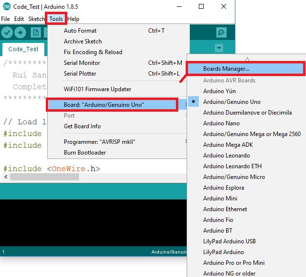
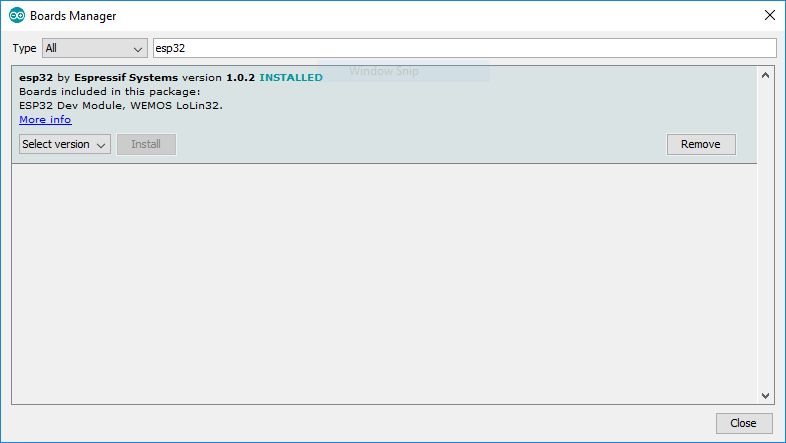
3 . Open the Boards Manager. Go to Tools > Board > Boards Manager…
4 . Search for ESP32 and press install button for the “ESP32 by Espressif Systems“:
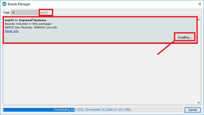
5 . That’s it. It should be installed after a few seconds.
First program for testing ESP32
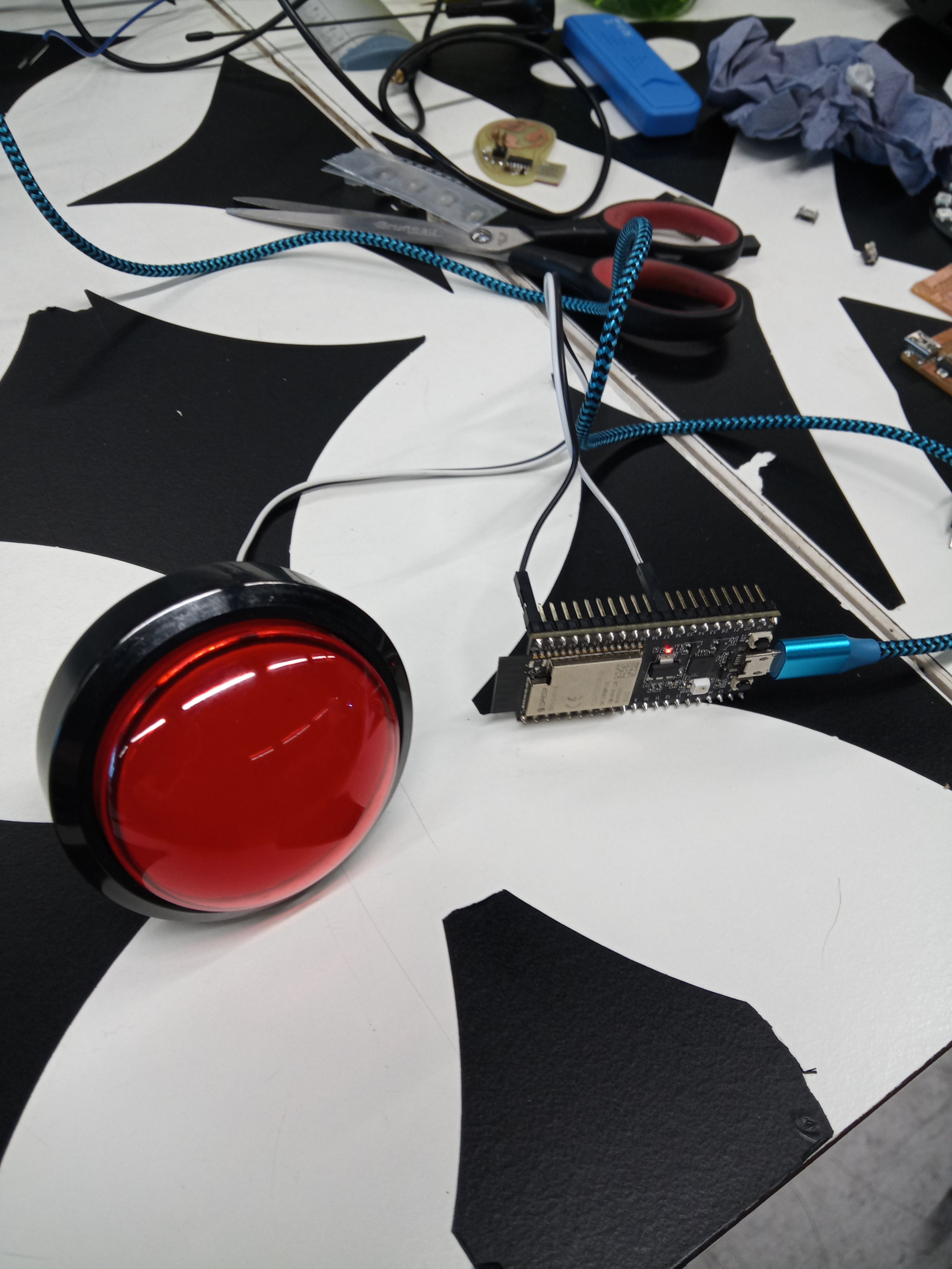
connection
Connect the button on PIN37 and GND
code
#define PIN_BUTTON 37
int state_btn = HIGH;


void setup() {
  // put your setup code here, to run once:
pinMode(PIN_BUTTON,INPUT_PULLUP);
Serial.begin(115200);
}

void loop() {
  // put your main code here, to run repeatedly:
int state_new = digitalRead(PIN_BUTTON);
if (state_btn && !state_new) {
Serial.println("pressed");
}
state_btn = state_new;
delay(1);
}
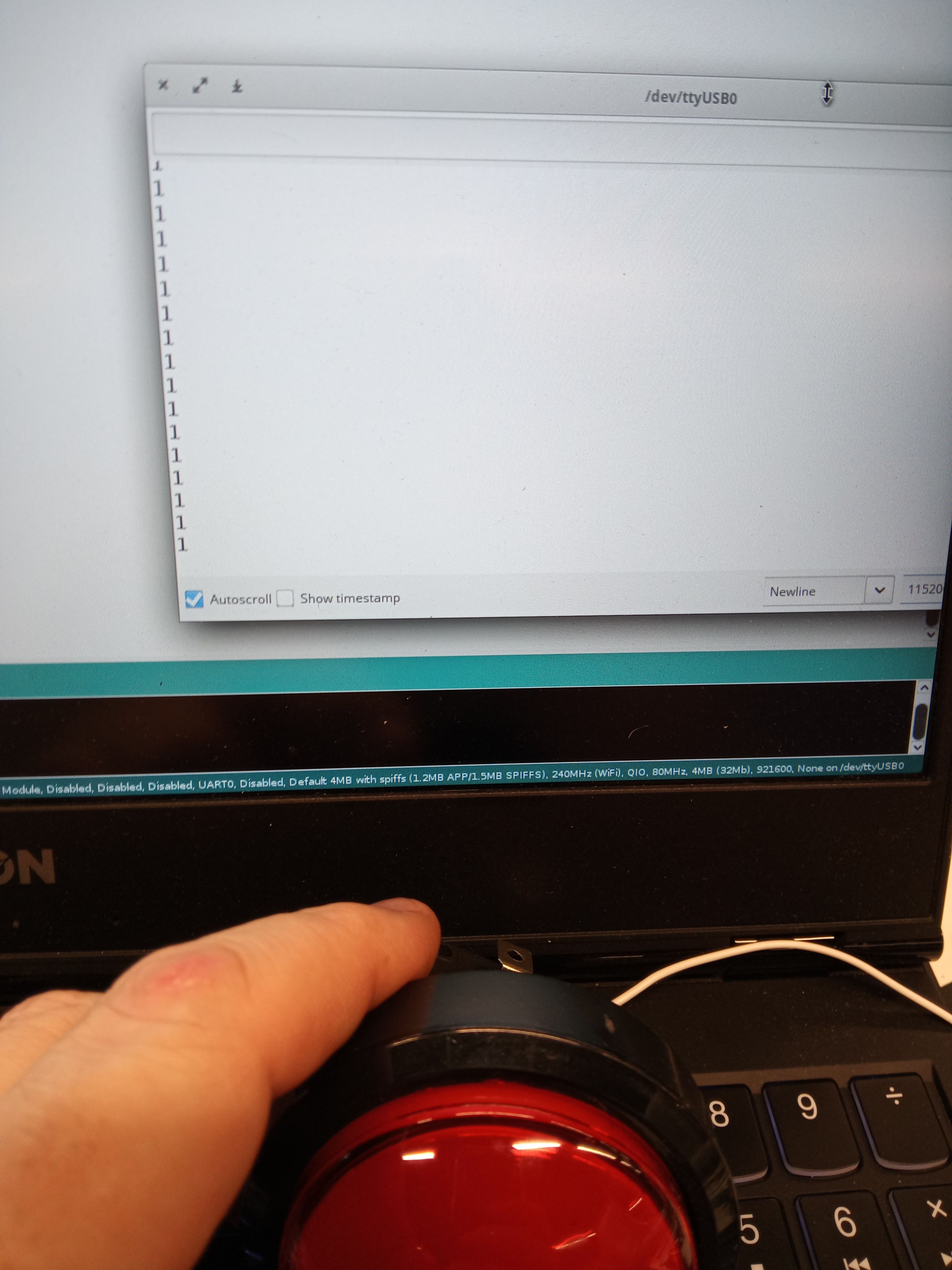
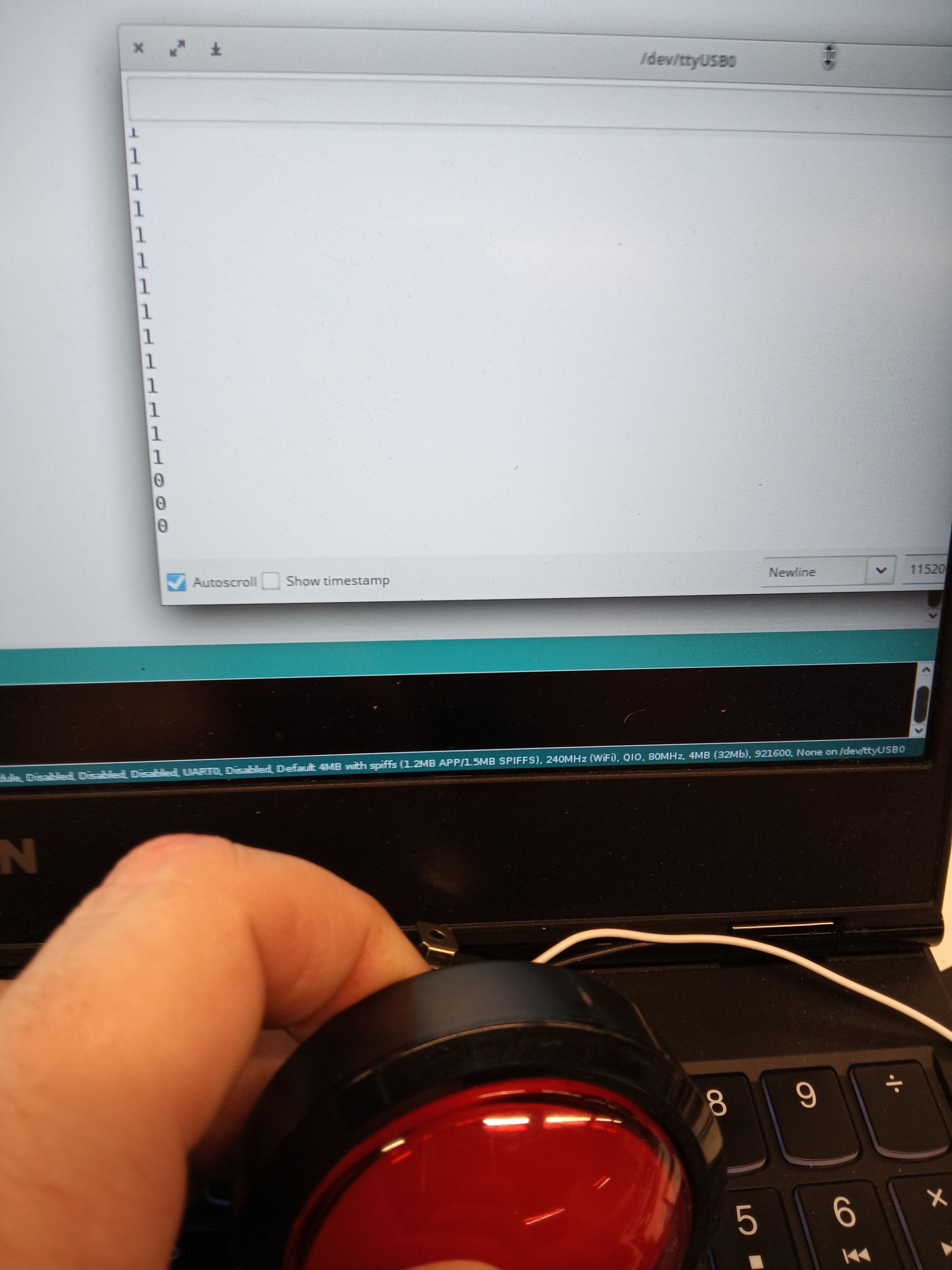
Result in picture
Second program for testing ESP32 with WIFI
To test the ESP32 with WiFi we need a broker to use the MQTT protocol
Mosquitto Installation
Eclipse Mosquitto is an open source (EPL/EDL licensed) message broker that implements the MQTT protocol versions 5.0, 3.1.1 and 3.1. Mosquitto is lightweight and is suitable for use on all devices from low power single board computers to full servers.
The MQTT protocol provides a lightweight method of carrying out messaging using a publish/subscribe model. This makes it suitable for Internet of Things messaging such as with low power sensors or mobile devices such as phones, embedded computers or microcontrollers.
For Ubuntu/Debian distribution
sudo apt install mosquitto
If this does not work, follow the procedure below
sudo apt-add-repository ppa:mosquitto-dev/mosquitto-ppa
sudo apt-get update
sudo apt install mosquitto
Test Mosquitto work
This code allows you to test the Wifi connection and see how Mosquitto reacts
#include <WiFi.h>

#define PIN_BUTTON 37
int state_btn = HIGH;

const char* wifi_ssid = "A6KE6K TEMP";
const char* wifi_password = "tempo8fi";

void setup() {
  pinMode(PIN_BUTTON,INPUT_PULLUP);
  Serial.begin(115200);
  WiFi.mode(WIFI_STA);
  WiFi.begin(wifi_ssid, wifi_password);
  Serial.print("Connecting to WiFi..");
  while (WiFi.status() != WL_CONNECTED) {
    Serial.print('.');
    delay(1000);
  }
  Serial.println("");
  Serial.println(WiFi.localIP());
}

void loop() {
  // put your main code here, to run repeatedly:
int state_new = digitalRead(PIN_BUTTON);
if (state_btn && !state_new) {
Serial.println("pressed");
}
state_btn = state_new;
delay(1);
}
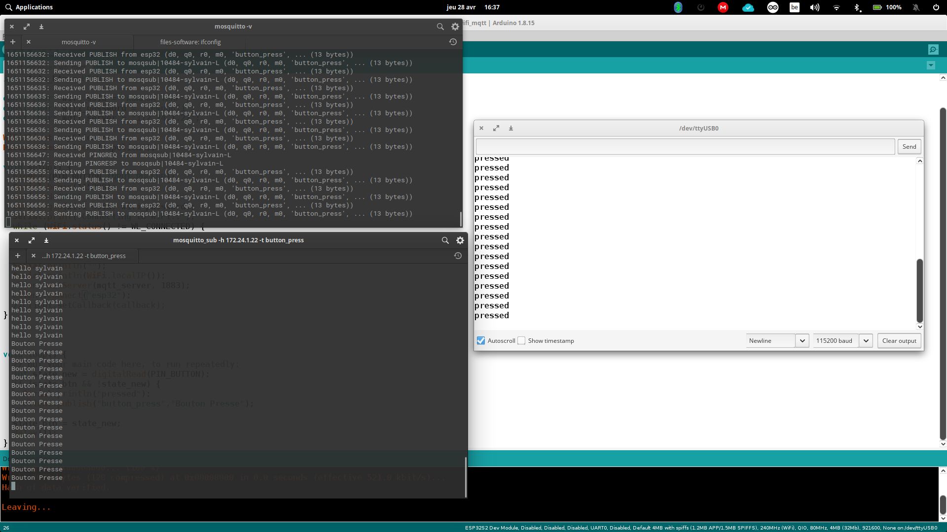
Result
First window, starting mosquitto with the command
mosquitto -v
The second window shows the result of the following command. Mosquitto reads and gives the answer.
mosquitto_sub -h 172.24.1.22 -t button_press
The third window is the arduino IDE serial monitor. It allows to check the operation when the button is pressed.
Group assignment
Group Link : link
For the group work, we worked with an ESP32 with the button on one side and the SAMD 21E17 DEVKIT with a NeoPixel ring on the other.
code
#include <WiFi.h>
#include <PubSubClient.h>
#define PIN_BUTTON 37
int state_btn = HIGH;

const char* wifi_ssid = "A6KE6K TEMP";
const char* wifi_password = "tempo8fi";
const char* mqtt_server = "172.24.1.22";

WiFiClient espClient;
PubSubClient client(espClient);

int count_sleep = 0;

void setup() {
  pinMode(PIN_BUTTON,INPUT_PULLUP);
  Serial.begin(115200);
  WiFi.mode(WIFI_STA);
  WiFi.begin(wifi_ssid, wifi_password);
  Serial.print("Connecting to WiFi..");
  while (WiFi.status() != WL_CONNECTED) {
    Serial.print('.');
    delay(1000);
  }
  Serial.println("");
  Serial.println(WiFi.localIP());
  client.setServer(mqtt_server, 1883);
  client.connect("esp32");
  //client.setCallback(callback);
}


void loop() {
  // put your main code here, to run repeatedly:
  int state_new = digitalRead(PIN_BUTTON);
  if (state_btn && !state_new) {
    Serial.println("pressed");
    client.publish("button_press","Bouton Presse");
  }
  state_btn = state_new;
  delay(1);
  count_sleep++;
  if (count_sleep == 5000) {
    client.publish("esp32", "still connected");
    count_sleep = 0;
  }
}
On the PC that has the samd with the neopixel ring, we will first install
in terminal
pip3 install paho-mqtt
A python code will have to be run to do our tests. Here is the code
import paho.mqtt.client as mqtt
import serial


mqtt_broker = "172.24.1.22"
ser_port = None


def on_message(client, userdata, message):
    global ser_port
    if message.topic == "button_press":
        print(f'Received:\n  topic: {message.topic}, message: {message.payload.decode("utf-8")}')
        ser_port.write(b"g")


def main():
    global ser_port

    print("Opening serial...")
    ser_port = serial.Serial("COM6", 115200)
    print("done!")

    client = mqtt.Client("my_pc")
    client.connect(mqtt_broker)

    client.on_message = on_message

    client.subscribe("button_press")

    try:
        client.loop_forever()
    finally:
        print("Closing serial...")
        ser_port.close()


if __name__ == '__main__':
    main()
This the code for de SAMD with the neopixel ring.
#include <Adafruit_NeoPixel.h>

#define PIN 2
#define NUMPIXELS 12
Adafruit_NeoPixel pixels(NUMPIXELS, PIN, NEO_GRB + NEO_KHZ800);

#define DELAYVAL 20

void setup() {
  pixels.begin();
  SerialUSB.begin(115200);
}

void circle() {
  pixels.clear();
  for(int i = 0; i < NUMPIXELS; i++) {
    pixels.setPixelColor(i, pixels.Color(0, 50, 0));
    pixels.show();
    delay(DELAYVAL);
  }
  for(int i = 0; i < NUMPIXELS; i++) {
    pixels.setPixelColor(i, pixels.Color(0, 0, 0));
    pixels.show();
    delay(DELAYVAL);
  }
}

void loop() {
  if (SerialUSB.available()) {
    char c = SerialUSB.read();
    if (c == 'g') {
      // go!
      circle();
    }
  }
}
code : neopixel_samd.ino
Finally, it remains to run the python code to see the whole thing work (see the videos below)
python3 mqtt_test.py
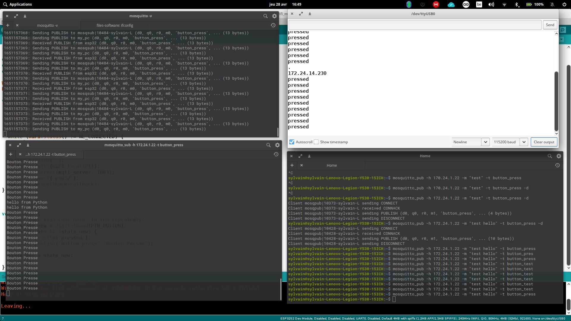
Result
When the button is pressed, the message “button pressed” appears and the ring lights up via the second computer
 )
)
This is the result with 2 computers
 )
)
Videos
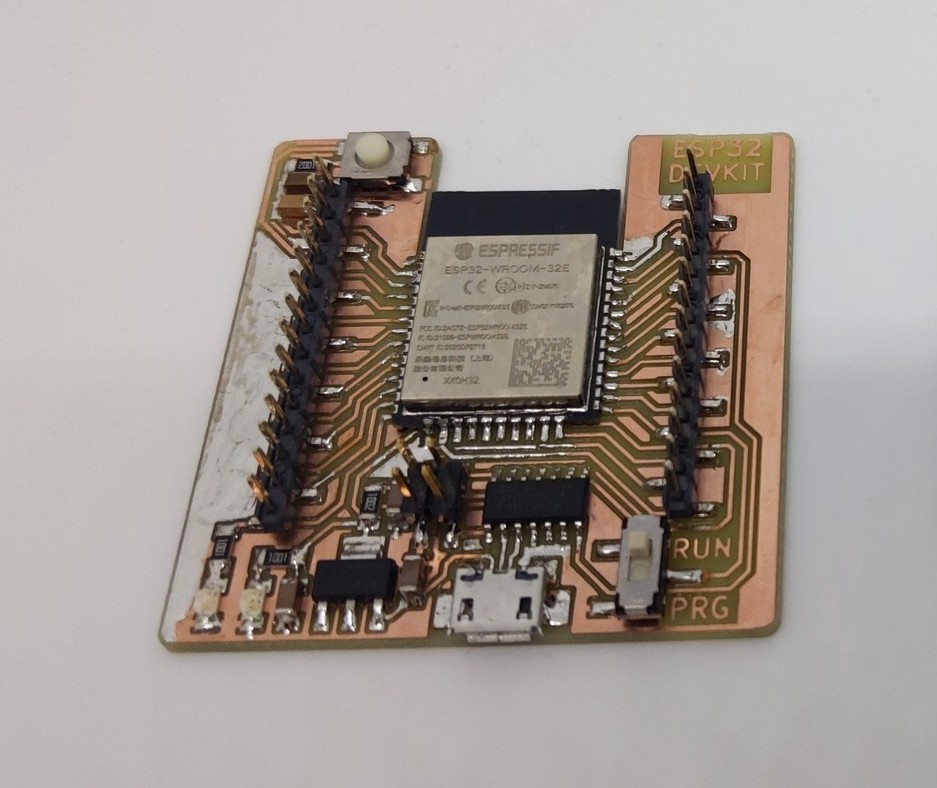
Bonus 1 - Design of a DevKit ESP32
With Quentin, it was decided to create this board in order to work on it. After the design, we decided to work with the “commercial” ESP32 while waiting for the DEV KIT to be created. After soldering the components, here is the result:
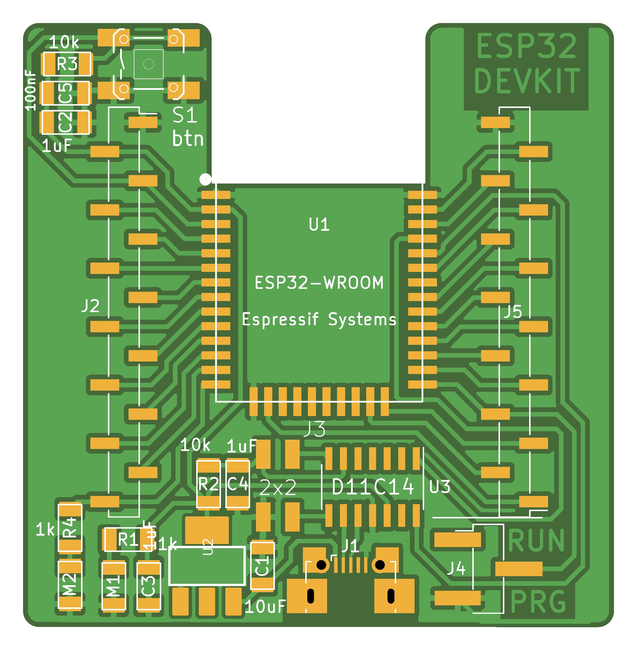
Files : esp32_devkit.zip
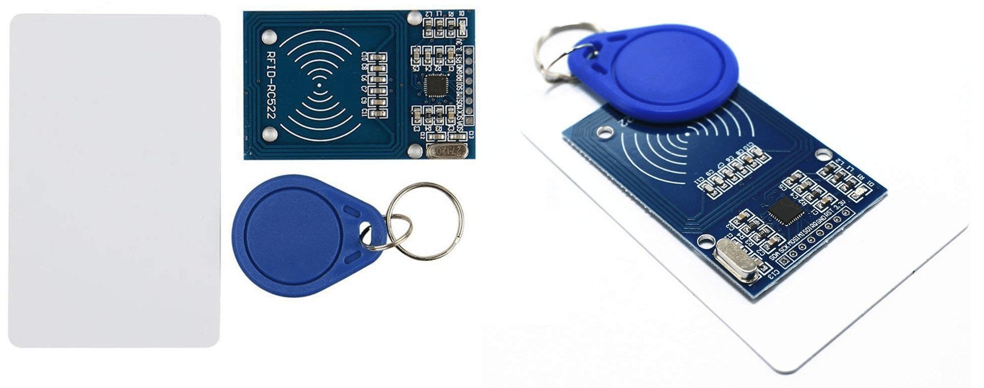
Bonus 2 - use of an RFID card instead of the button
The idea is very simple, use an RFID card or badge to replace the button on our assembly.
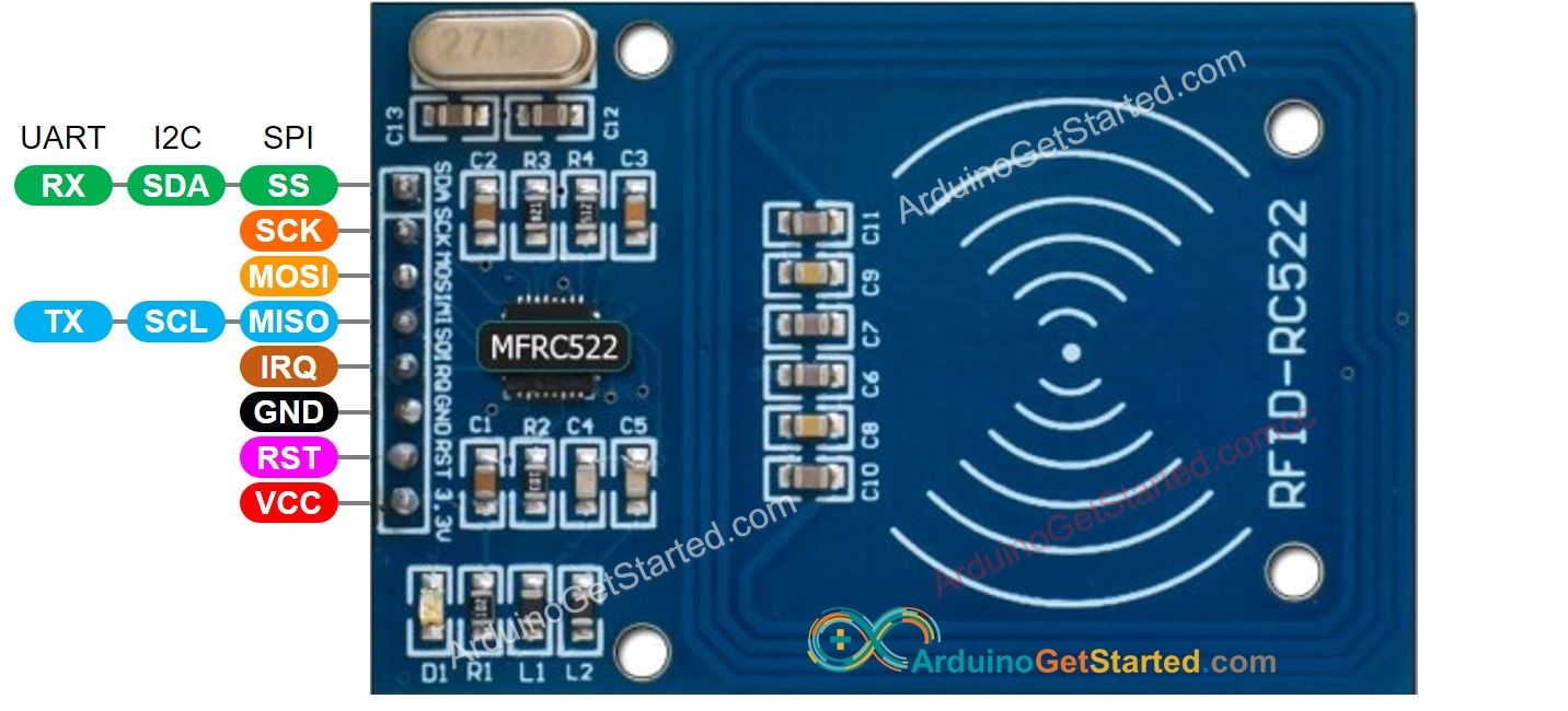
About RFID-RC522 Module
RFID-RC522 Module Pinout
RFID-RC522 has 8 pins, some of them are common pins, the others are shared among three communication modes: SPI, I2C, UART. At a time, only one communication mode can be used. The pin are:
- GND pin: needs to be connected to GND (0V)
- VCC pin: needs to be connected to VCC (3.3)
- RST pin: is a pin for reset and power-down. When this pin goes low, hard power-down is enabled. On the rising edge, the module is reset.
- IRQ pin: is an interrupt pin that can alert the microcontroller when RFID tag comes into its vicinity.
- MISO/SCL/TX pin: acts as MISO when SPI interface is enabled, acts as SCL when I2C interface is enabled and acts as TX when UART interface is enabled.
- MOSI pin: acts as MOSI when SPI interface is enabled.
- SCK pin: acts as SCK when SPI interface is enabled
- SS/SDA/RX pin: acts as SS when SPI interface is enabled, acts as SDA when I2C interface is enabled and acts as RX when UART interface is enabled.
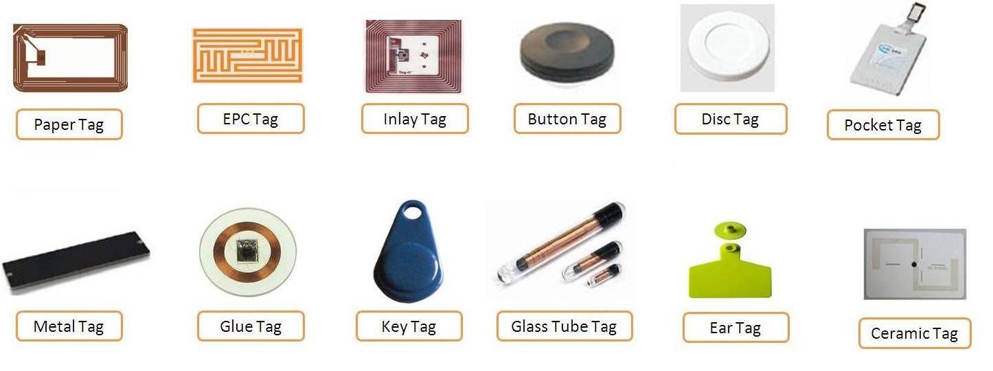
How RFID/NFC Works
RFID/NFC includes two components: reader and tag.
- The reader consists of a radio frequency module and an antenna which generates high frequency electromagnetic field.
- The tag is usually a passive device, which doesn’t need to have power source. The tag contains a microchip that stores and processes information, and an antenna to receive and transmit a signal. The tag is used to store the information: UID (Unique ID) and data.
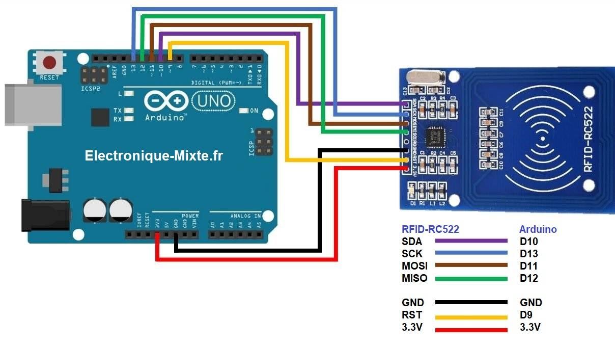
Wiring Diagram between RFID-RC522 Module and ESP32
Library installation
We need a library MFRC522
Search “MFRC522” in Arduino IDE , then find the library by GithubCommunity
Code
file :RFID.ino
#include <SPI.h>
#include <MFRC522.h>

#define SS_PIN 10
#define RST_PIN 5

MFRC522 rfid(SS_PIN, RST_PIN);

void setup() {
  Serial.begin(9600);
  SPI.begin(); // init SPI bus
  rfid.PCD_Init(); // init MFRC522

  Serial.println("Tap RFID/NFC Tag on reader");
}

void loop() {
  if (rfid.PICC_IsNewCardPresent()) { // new tag is available
    if (rfid.PICC_ReadCardSerial()) { // NUID has been readed
      MFRC522::PICC_Type piccType = rfid.PICC_GetType(rfid.uid.sak);
      //Serial.print("RFID/NFC Tag Type: ");
      //Serial.println(rfid.PICC_GetTypeName(piccType));

      // print NUID in Serial Monitor in the hex format
      Serial.print("UID:");
      for (int i = 0; i < rfid.uid.size; i++) {
        Serial.print(rfid.uid.uidByte[i] < 0x10 ? " 0" : " ");
        Serial.print(rfid.uid.uidByte[i], HEX);
      }

      Serial.println();
      Serial.print("hello");
      Serial.println();


      rfid.PICC_HaltA(); // halt PICC
      rfid.PCD_StopCrypto1(); // stop encryption on PCD
    }
  }
}
Result in video with card and tag
To be done
- Wiring on ESP32
- Replace the button
- Test operation by switching on the neopixel ring