Fab Academy 2022
Yousif Jalil's Website
RC Flying Car
What does it do?
RC Flying car is a combination between a drone and a RC car, It is a able act as both, a drone and a Rc Car, with a switch between the modes, in the future, in can be implemented in Fpv Drone Hobbiests who are into racing, as added challenge to race, the drone should pass aerial obstacles and the land and pass the ground obstacles, as a use case for this drone.
Whats done beforehand?
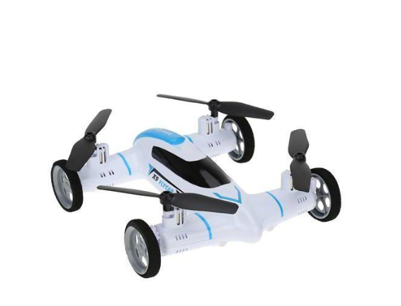
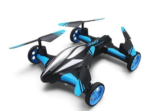
Therer are a few toy manufacturers that have done something similar like these products,
What did you design?
In this project I will Design the Following:
- Electronics design(PCB)
- 3D Design of the Bottom side(3D Printed)
- 2D Design of the Top side(Laser Cut)
- Software(Multwii platform)
- Switch Mechanism (Drone and Car mode)
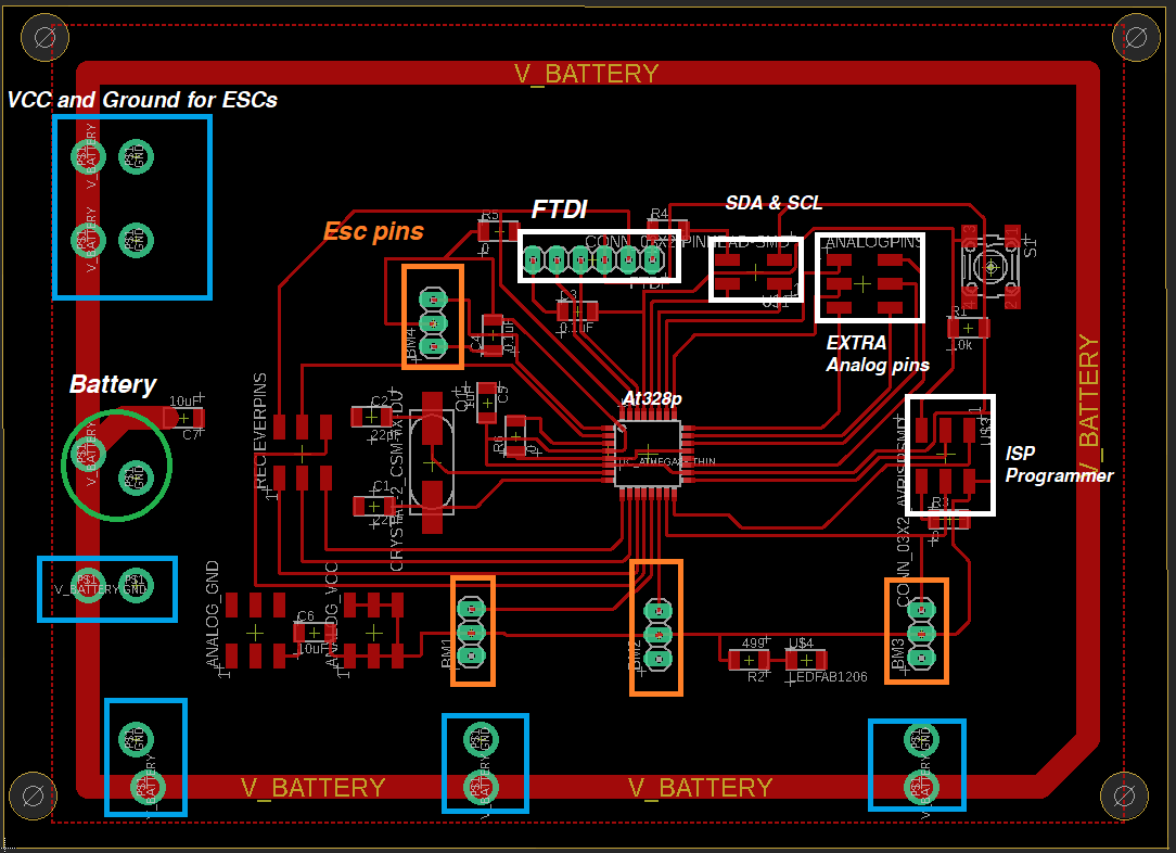
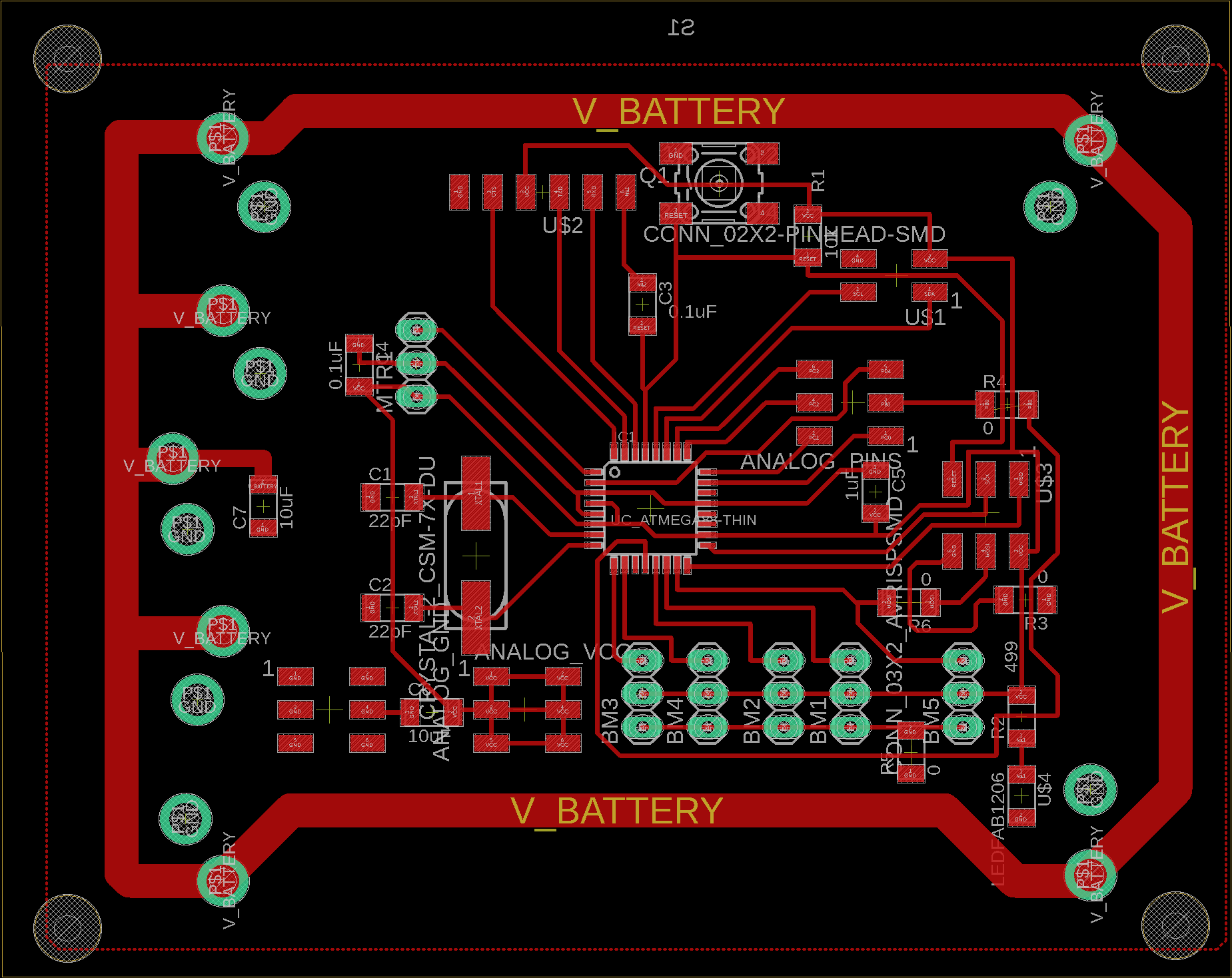
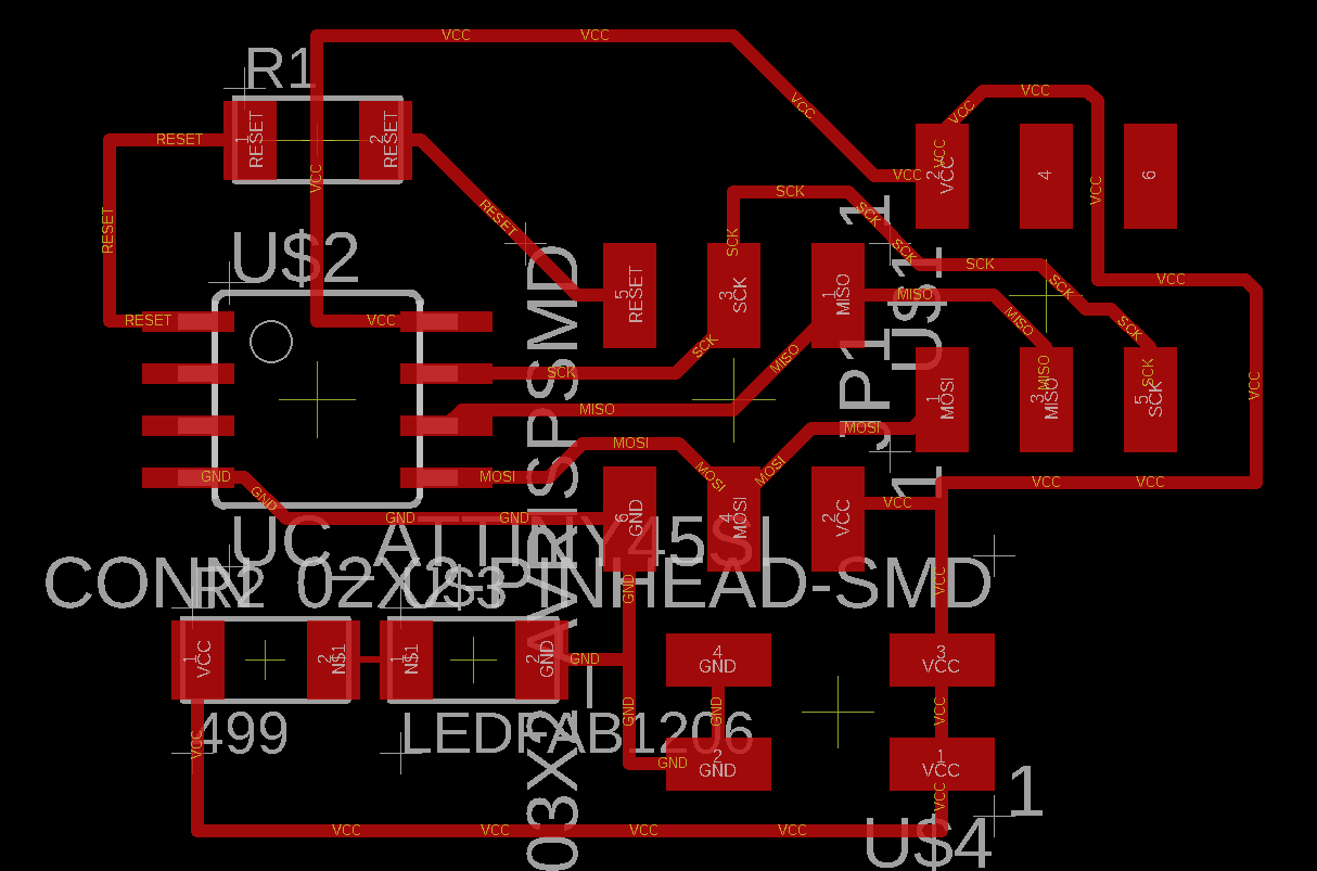
Electronics design(PCB)
For the Electronics Design, I made a board specifically to handle the use of my project + it can be also used to deal with following assignmens. so that i can save time. It was also the same board the i designed on the Output Devices week.
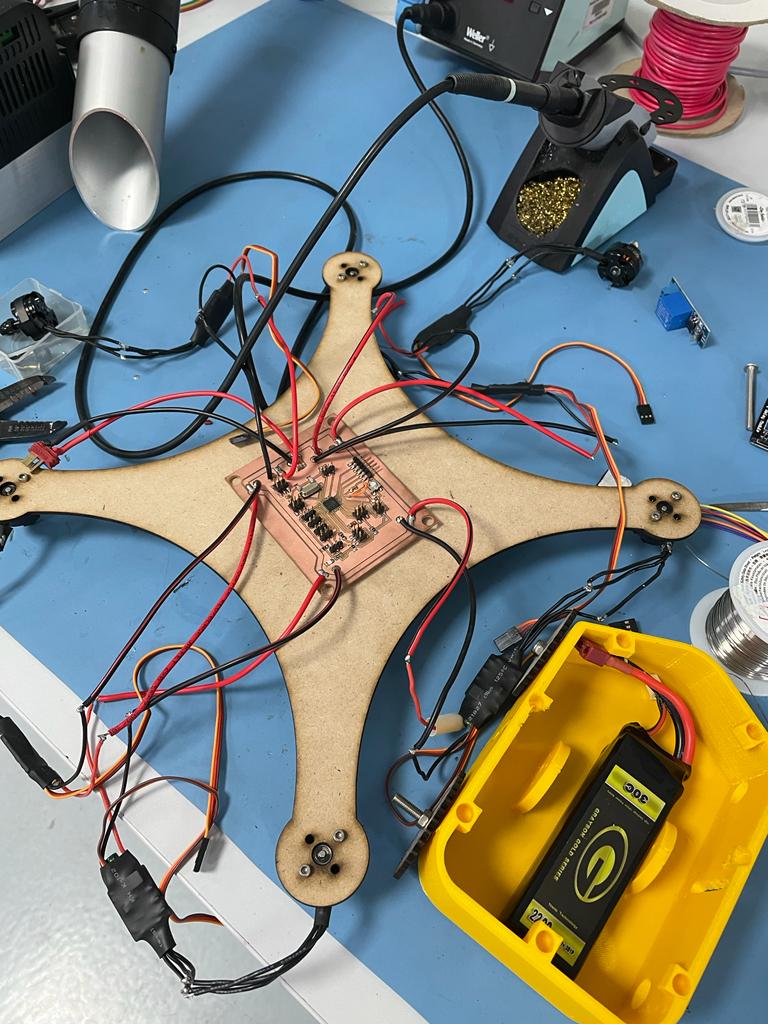
The Board incorporates all inputs and outputs that a drone requires, Ports for the ESCs signal wires, Battery to ESCs, Battery line, SDA and SDL for MPU-6050 same one i used in the Input Devices week.
Problems Encountered in PCB Design
During the PCB Design i have made another board, but i discovered later few mistakes:
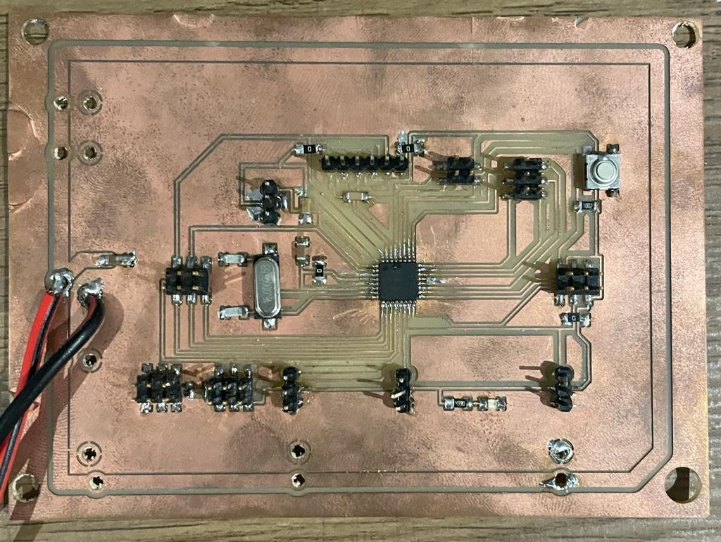
Very Thin Traces during the Design
During my eagle design i noticed that i was using very thin Trace size (0.06), which was the reason why traces come off later, while i was moving it and pluging wires and unpluging.
Pins Coming out
The Other problem is the pins coming out which was very stressful, because when the pins came out, usually they take the traces with them, which means i have to make another board.
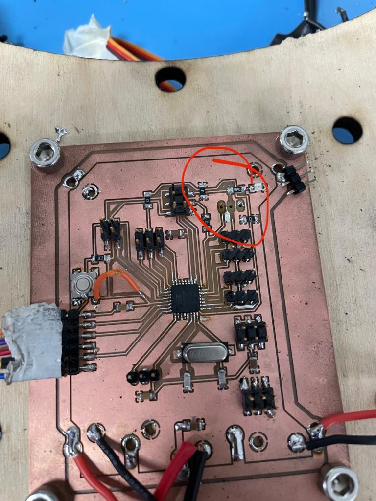
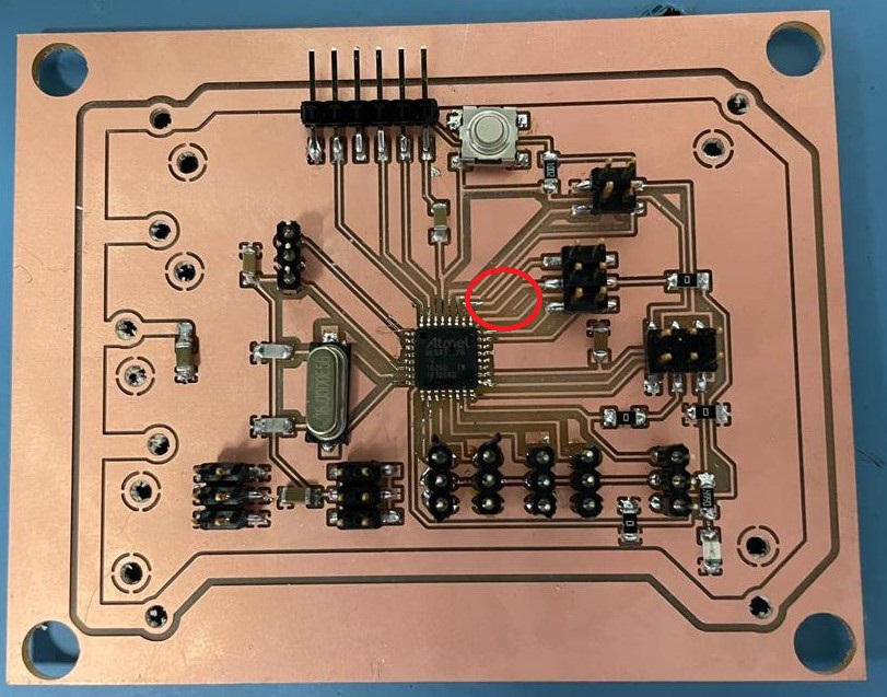
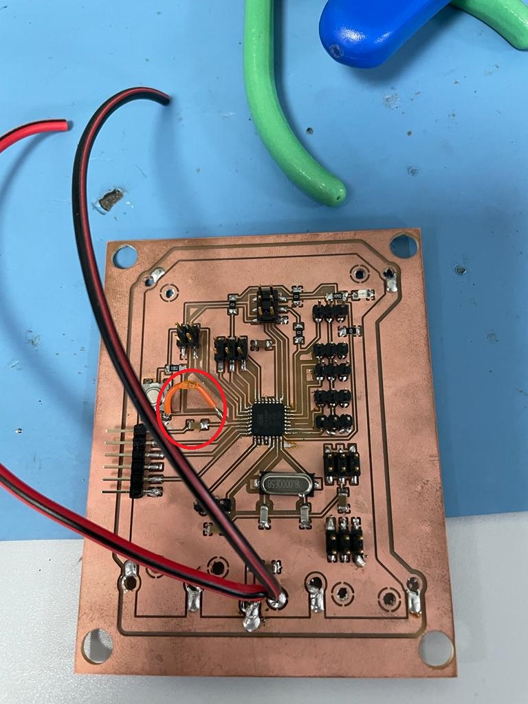
A Routing mistake
During the Design of this board, when i was routing the button connections I made a mistake, where i only routed one of the button pins and forgot the other one, so i had to solder a copper wire to connect it.
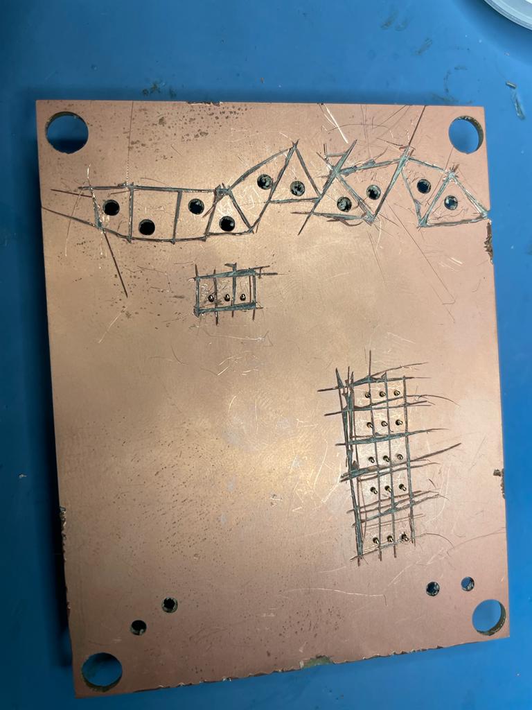
Using Double sided Copper Plate
As I was too much in a hurry to finish my board, I immeadiatly started milling the board, and i didn't notice that it was a double sided copper board until I started soldering the SMD components, this would mean that all the battery and ESCs pins would be connected together, so what i had to do is to carve the copper on these pins to isolate them from each other.
3D Design of the Bottom side(3D Printed)
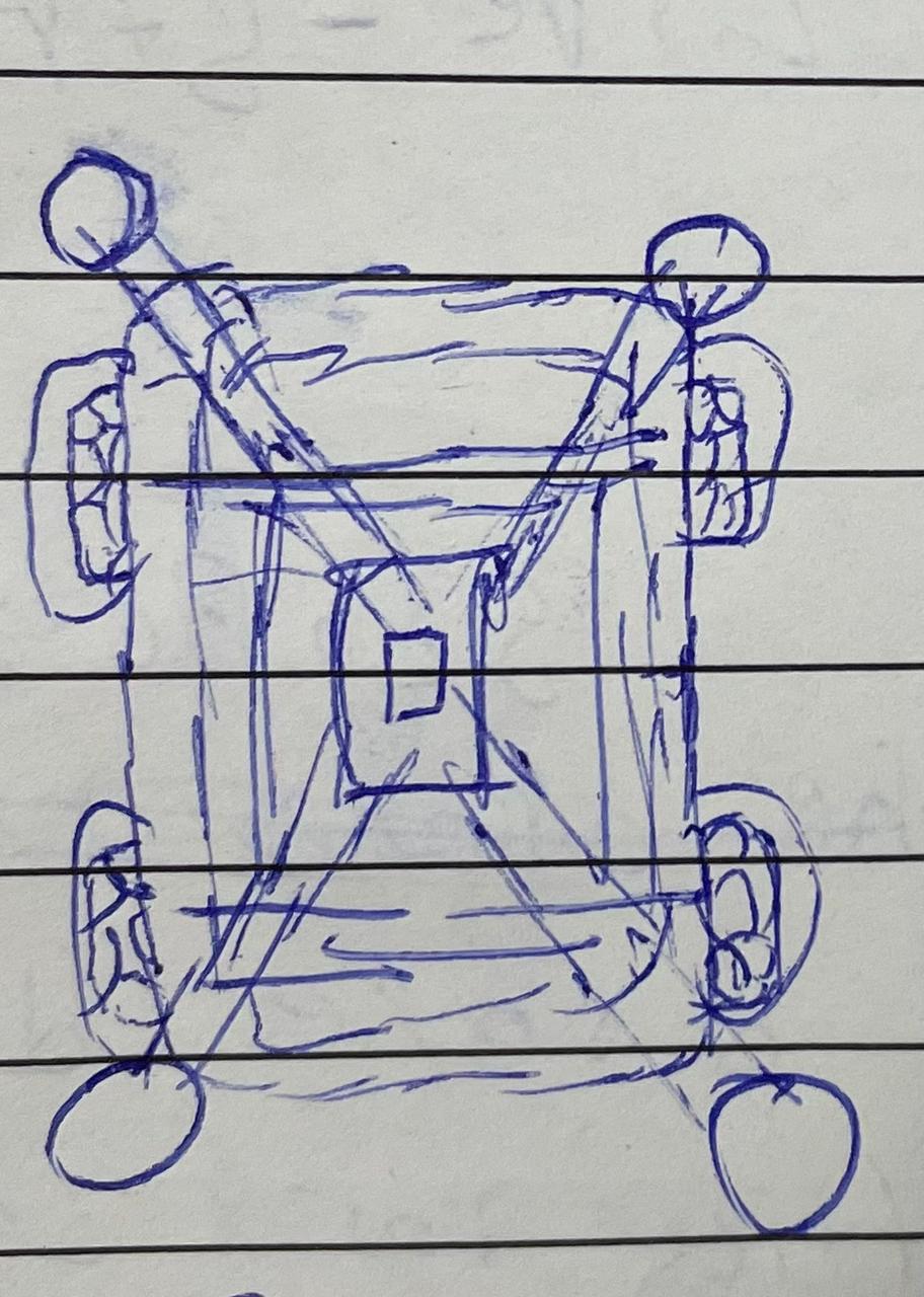
I used the Fusion 360 To design the bottom part which will be carrying the bottom parts, such as brushless motors, PCB, electronics to hold the switching mechanism and the Battery. The bottom side should completely be sealed off by the top side which will be laser cut.
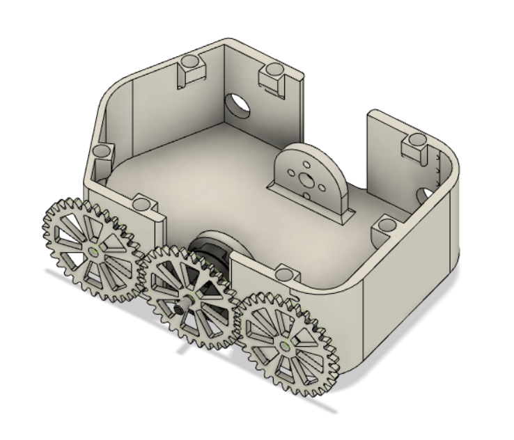
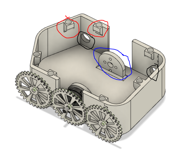
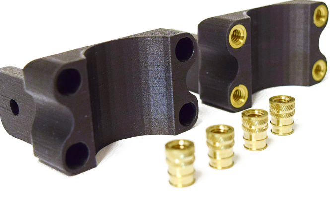
The Red Circles represents the 3D printed spaces for the heat Inserts that that are needed for the top side to be screwed on.
The Blue Circle shows where the brushless motor will be mounted on, it should have enough distance so that it can move the gear that is attached to it with other gears to ensure smooth movement of the wheels.
The black circle shows where the screws that hold gears would go.
Laser Cutting the Gears
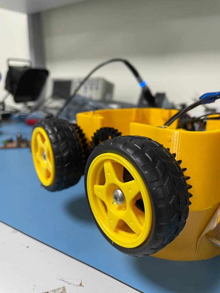
3D Printing the Bottom side
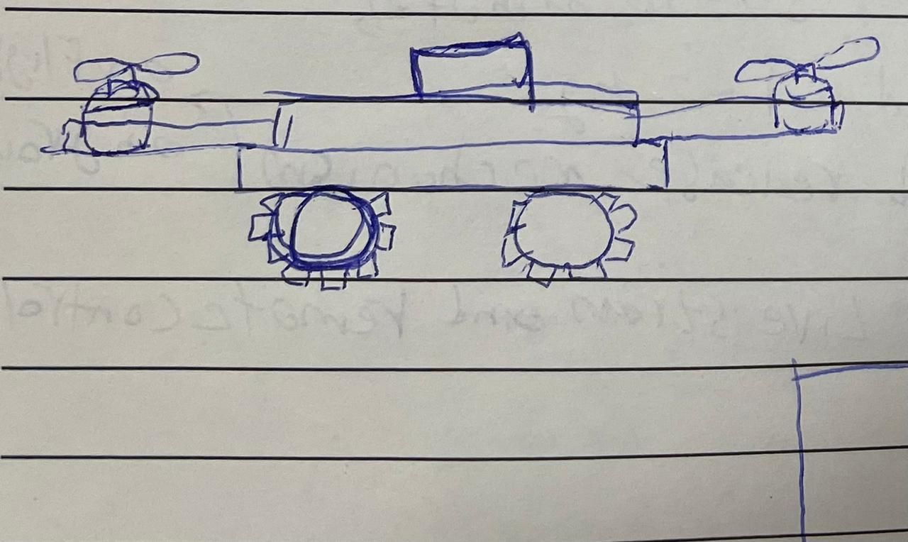
2D Design of the Top side(Laser Cut)
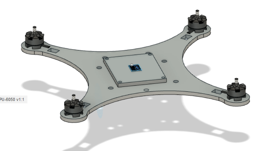
I decided to use the Plywood sheets for the top side, to hold both motors and the propellers, the circuit board and the MPU6050 which is important to the positioning of the drone.
Cutting the Plywood using the Laser Cutter
Frame Assembly
Software(Multwii platform)
To actually control the drone and make it fly, I have used the Multiwii platform. MultiWii is an open source software project aiming to provide the brain of a RC controlled multi rotor flying platform. It is compatible with several hardware boards and sensors. It can be setup on the At328p board.
To set up the Multiwii software on my board I refereced Daniele Ingrassia Satsha's Kit and flight controller, used a similar approach to program my board.
Switch Mechanism (Drone and Car mode)
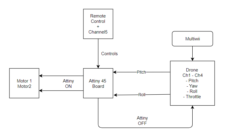
One of the most important parts of the project is the switching mechanism between the drone mode and the RC car mode, the idea is to switch using the Remote control, and to do that i made a smaller attiny board with relays.
The Remote Control has five channels four of them which will be used by Multiwi software for the drone functionality, and there is one free channel, the idea is to make two of channels that are going to be used by the multiwi software work in both modes, one in drone mode, the other is RC car mode, and to achieve this switch i made a smaller board to control this mechanism.
The switching mechanism way of working looks like this diagram.
Attiny Code
int value ;
int Channel5 = 2;
int relay1 = 1;
int relay2 = 0;
void setup() {
//pinMode(Channel5,INPUT);
pinMode(relay1, OUTPUT);
pinMode(relay2, OUTPUT);

}
void loop() {

 value=pulseIn(Channel5, HIGH);

  if (value  1200)
 digitalWrite(relay1, HIGH);
 digitalWrite(relay2, HIGH);
 delay(1000);

}
else if (value > 1200) {
 digitalWrite(relay1, LOW);
 digitalWrite(relay2, LOW);
}

}
What materials and components were used?
Component |
Source |
Cost |
| PLA Filament | FabLab UAE | 155 AED |
| Atmega328p | FabLab UAE | 12 AED |
| 2500mAh Lithium Ion (LiPo) Battery | FabLab UAE | 39 AED |
| Plywood sheet | FabLab UAE | 155 AED |
| Propellers | FabLab UAE | 60 AED |
| Wheels | FabLab UAE | 60 AED |
| Brushless motors | FabLab UAE | 60 AED |
| Electronic speed controllers | FabLab UAE | 60 AED |
| Remote Control | FabLab UAE | 60 AED |
What Parts and Systems were made?
- PCB- 3D Printed Parts
- Laser Cut parts
What processes were used?
- 2D and 3D Design using Fusion 360- PCB Design Using Eagle
- Programming Using Arduino
- 3D Printing
- PCB Milling
