This Week's Tasks
individual assignment:
1-cut something on the vinylcutter
2-design, lasercut, and document a parametric construction kit,
accounting for the lasercutter kerf,
which can be assembled in multiple ways.
-extra credit include elements that aren't flat.s
Group assignment:
3-characterize your lasercutter's focus, power, speed, rate,
kerf, joint clearance and types.
Link
1- Cut something on the vinylcutter
For the Vinyl i cutting we first watched a video on vinyl cutting. Then we went to choose an image we want to use on the vinyl cutter, I choose an image of a wolf.

Preping the image for cutting in Inkscape
We have to change the picture from Raster to Vector format using Inkscape, Here are the steps, Thanks to Eng.Hashim for the Explanation.
Open Inkscape and Add your Picture
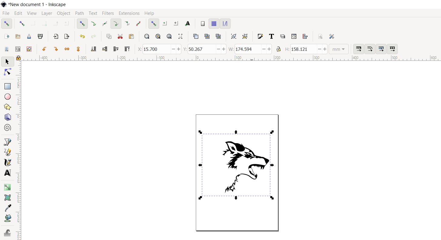
Convert your Raster Picture to Vector by goint to Path -> Object tracemap
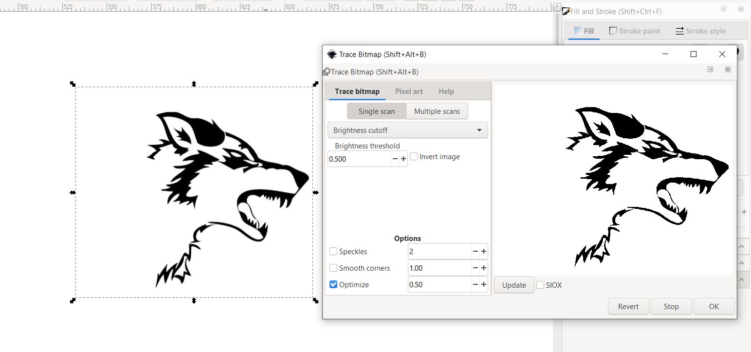
Keep playing with the setting until you get a good result
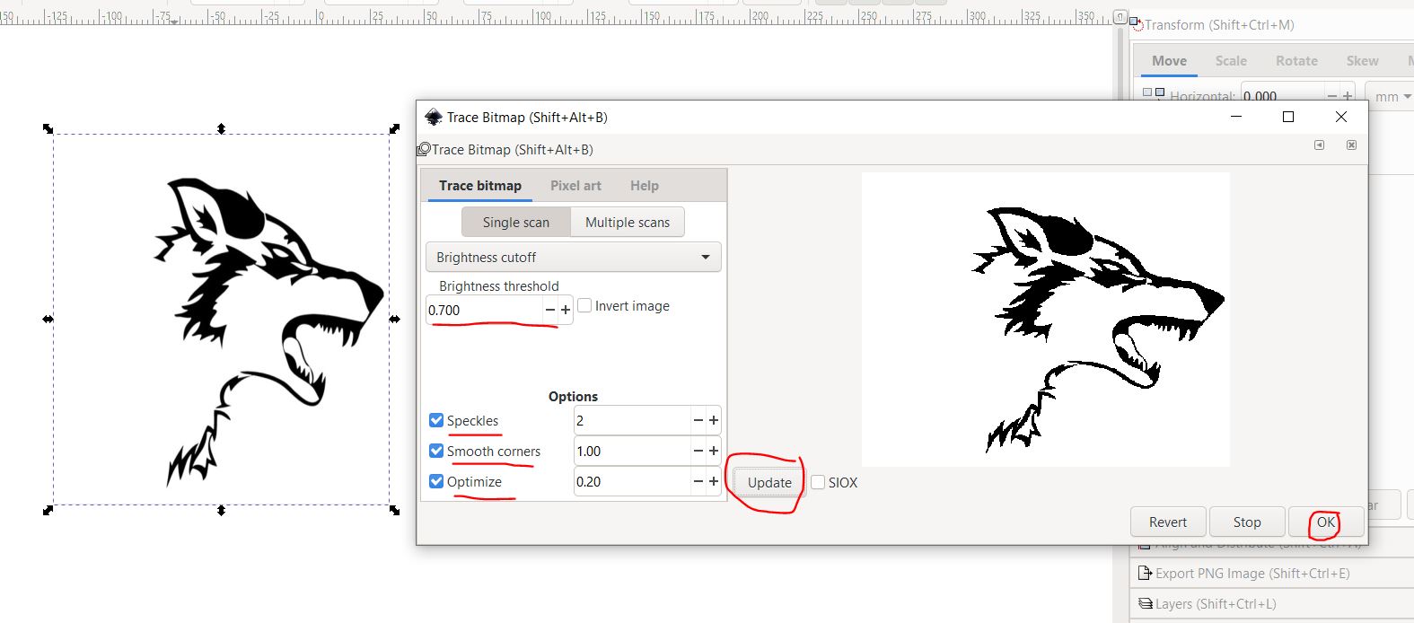
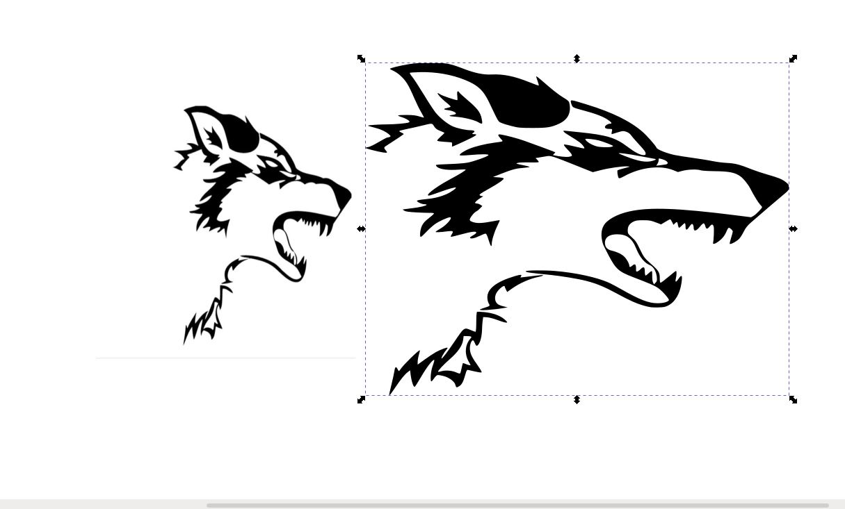
Here is the result, delete the raster picture.
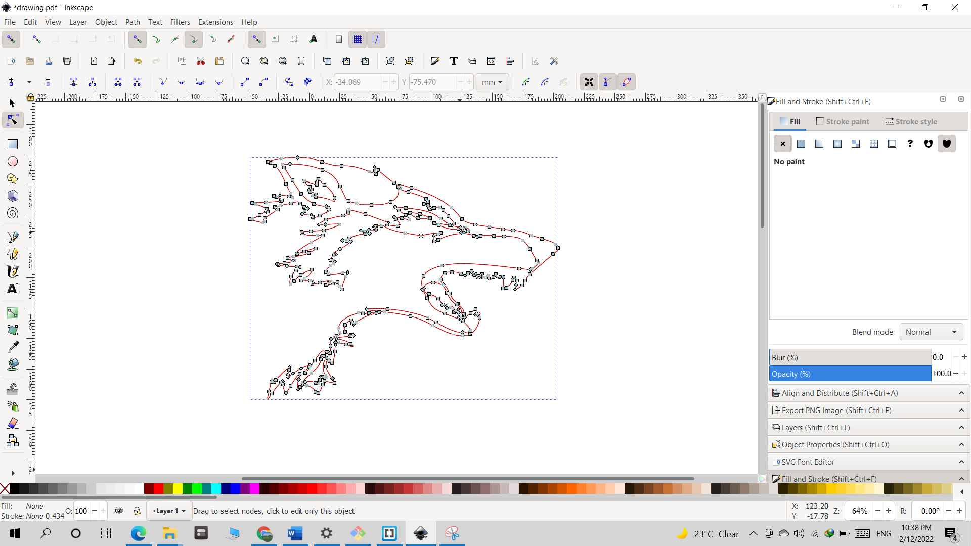
Double click on the picture until you see the nodes and then click "Convert selected object's strokes to path"
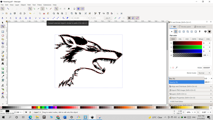
Now you should only be able to see the outlines, then save as pdf
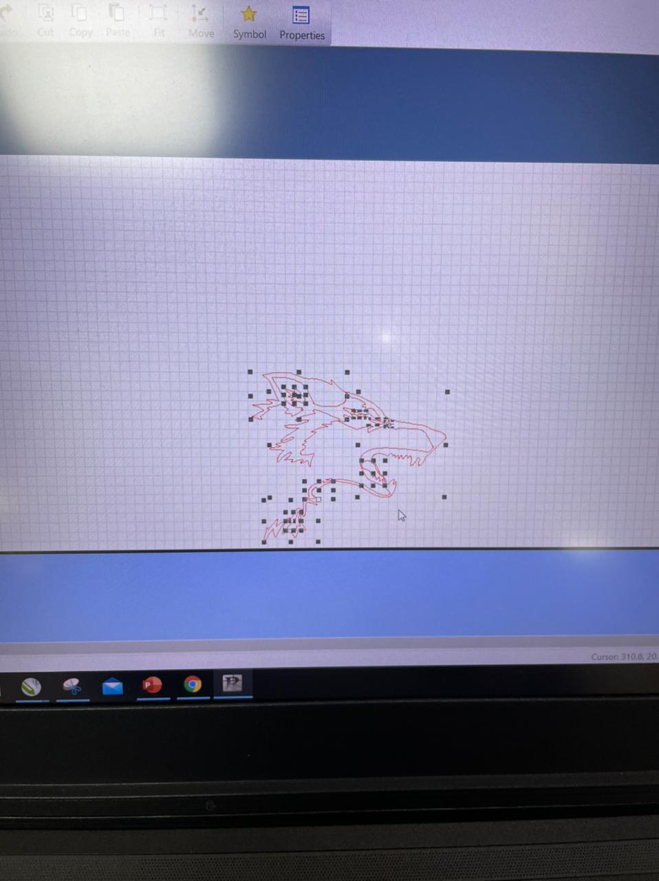
From Inkscape to Vinyl Cutter
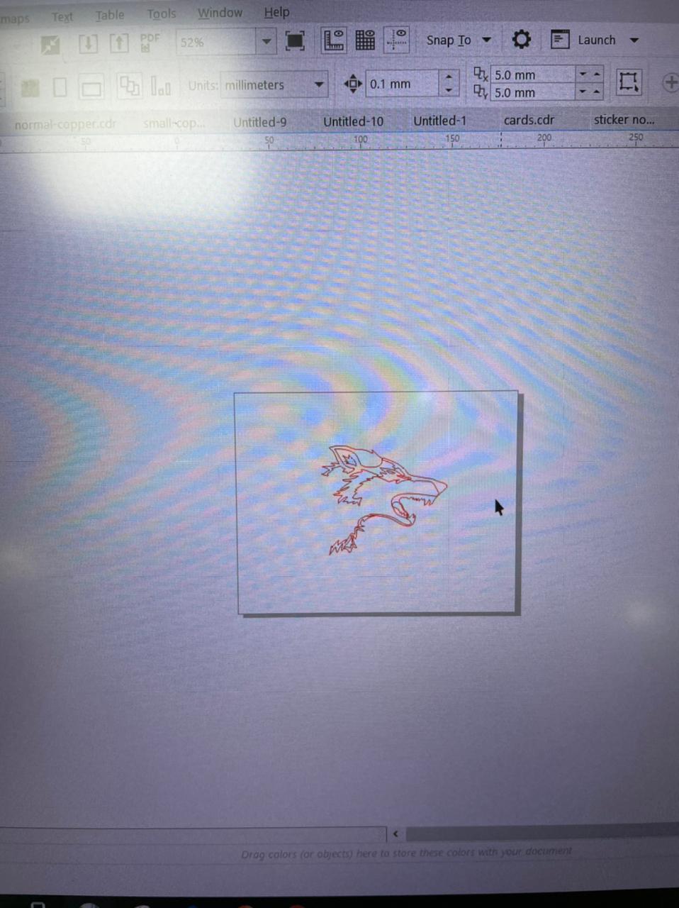
Open CorelDraw and Insert your Pdf image, Position it and size it acording to your desired size,
In CorelDraw you will see an extension for the roland machine for cutting, click Output paths to CutStudio
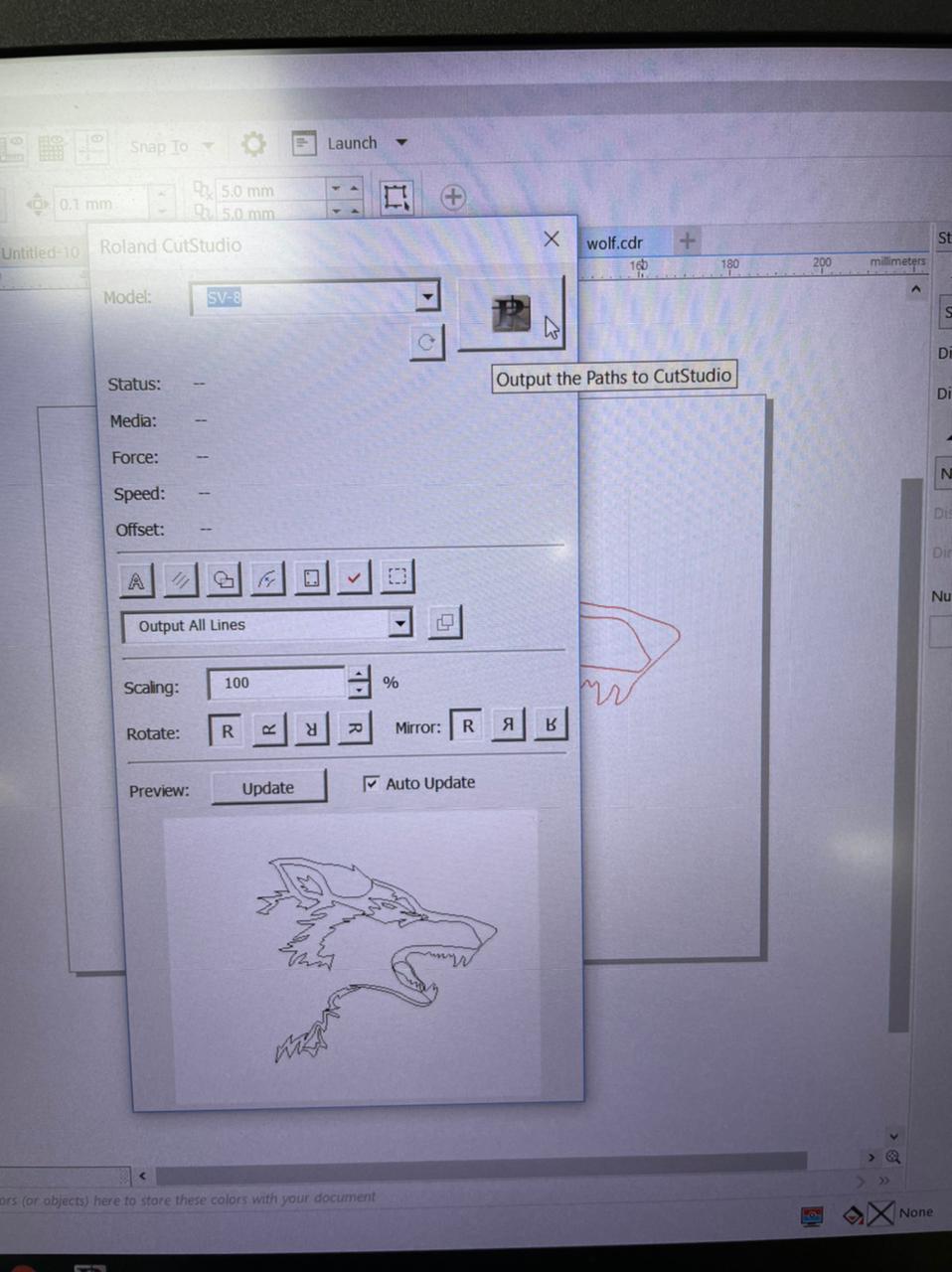
It Will take you to the main screen of the studio
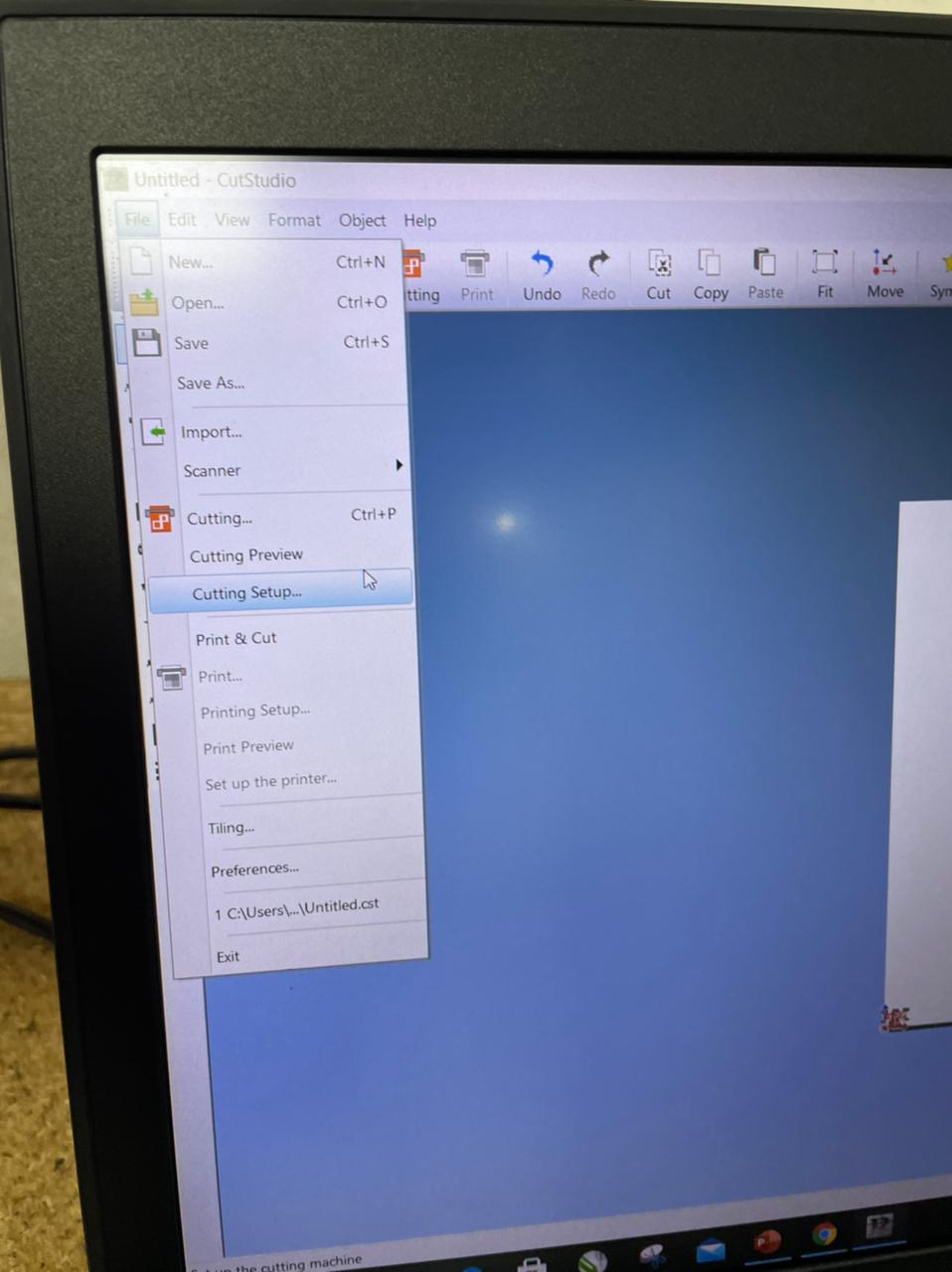
Then you should go to files -> Cutting setup, to adjust the details of the cut
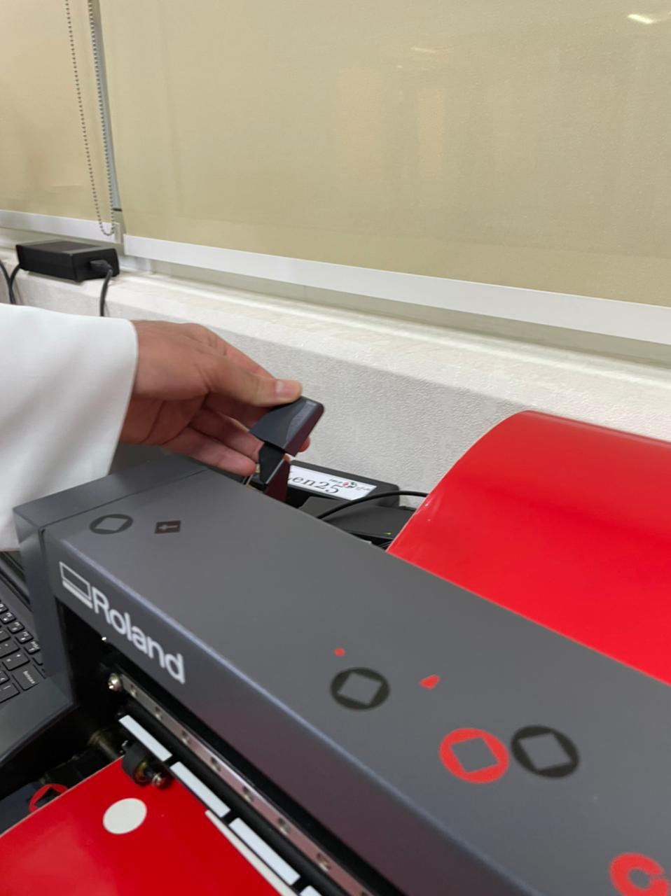
Before Cutting don't forget to push the lever so the vinyl roll is tight
Video of the Cutting Process
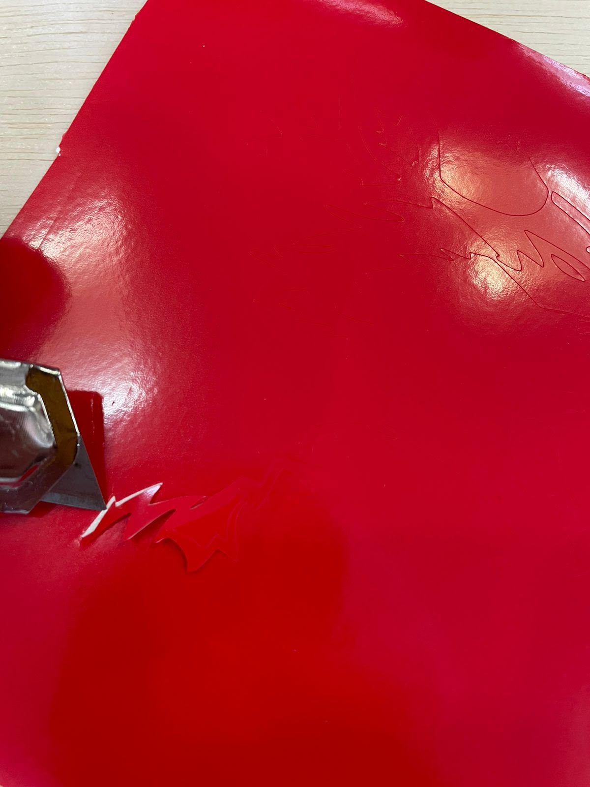
Here is the result after cutting it's not very clear
After Weeding
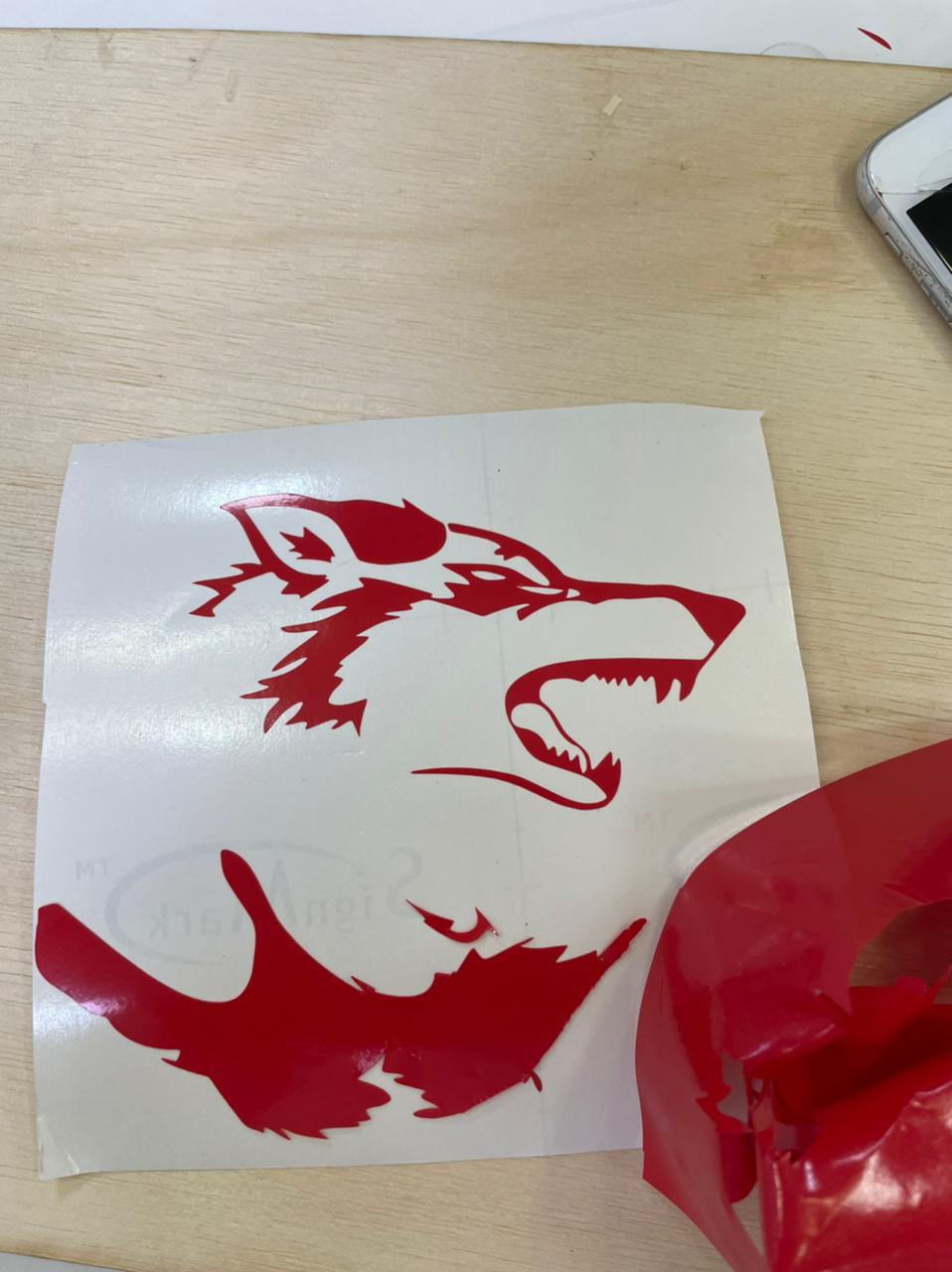
Transfering the vinyl cut to another roll
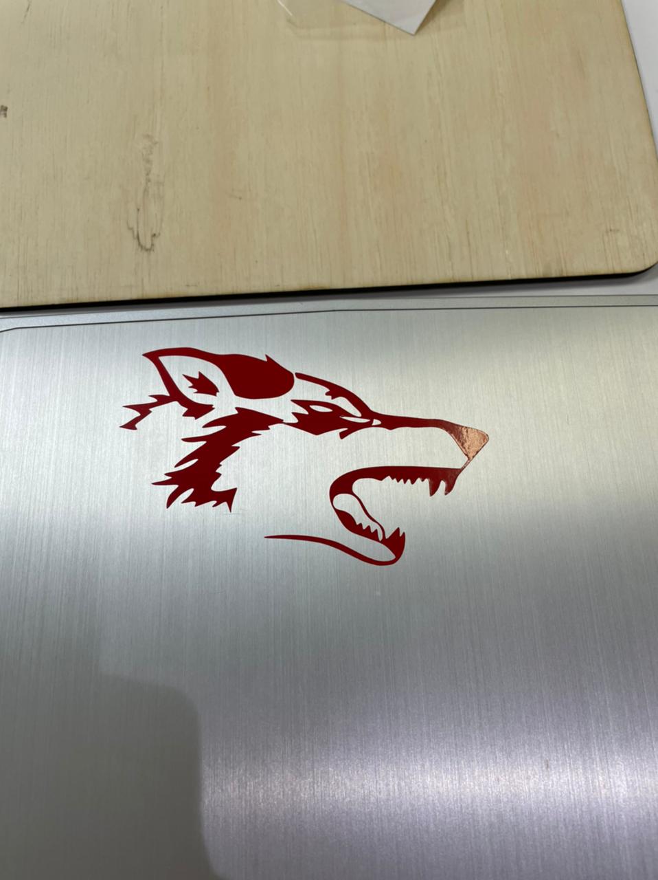
From the Roll to the Laptop
And Here is the Final Result on the Laptop
2-design, lasercut, and document a parametric construction kit, accounting for the lasercutter kerf, which can be assembled in multiple ways.
For this week, i almost had zero ideas for what i wanted to make but the constant thing that must be considered that it should be parametric, i hade this idea to make a dumbell like in the gym out of cardboard, and this how i designed it using F360.
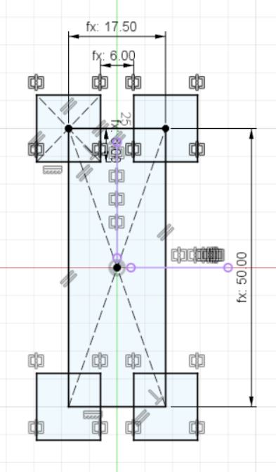
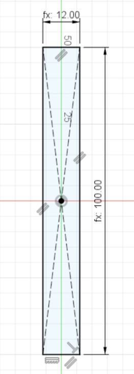
First i made a 6 edged polygon and gave it a length 25mm
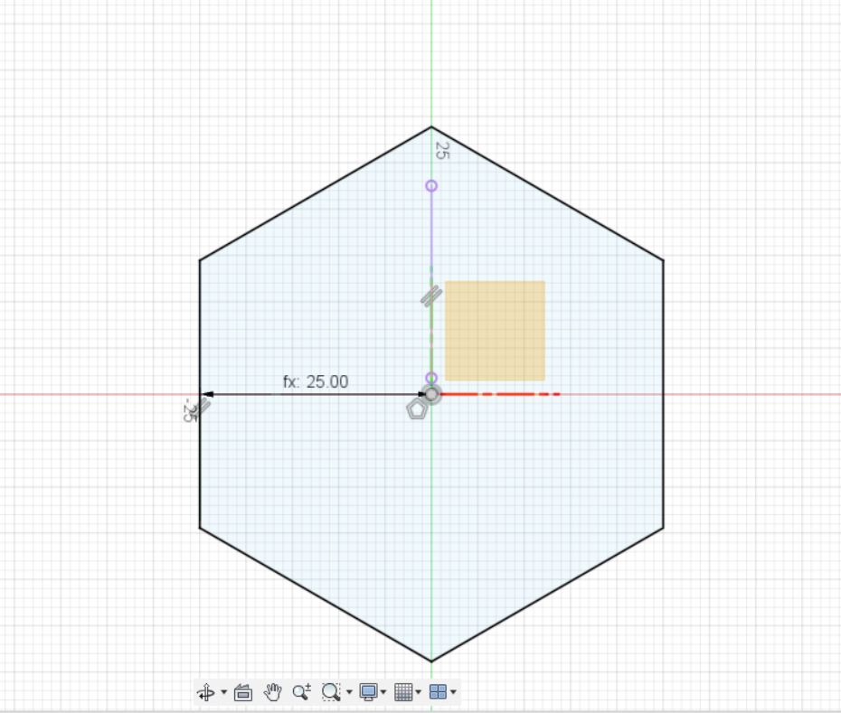
Then to give the polygon thickness i needed to add a few walls so i added a square hole
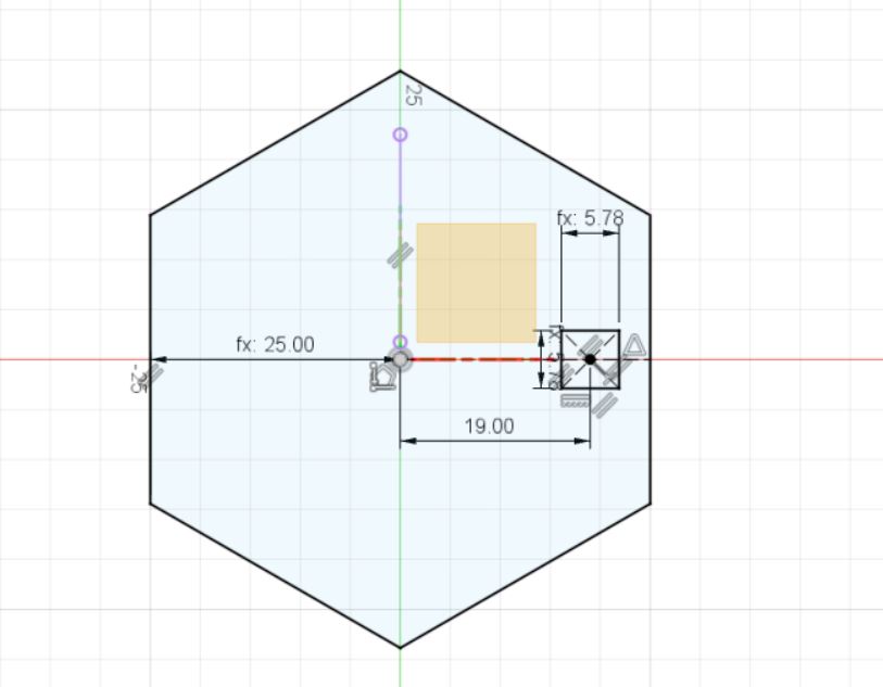
I added square holes on all the sides of the polygon using the array feature
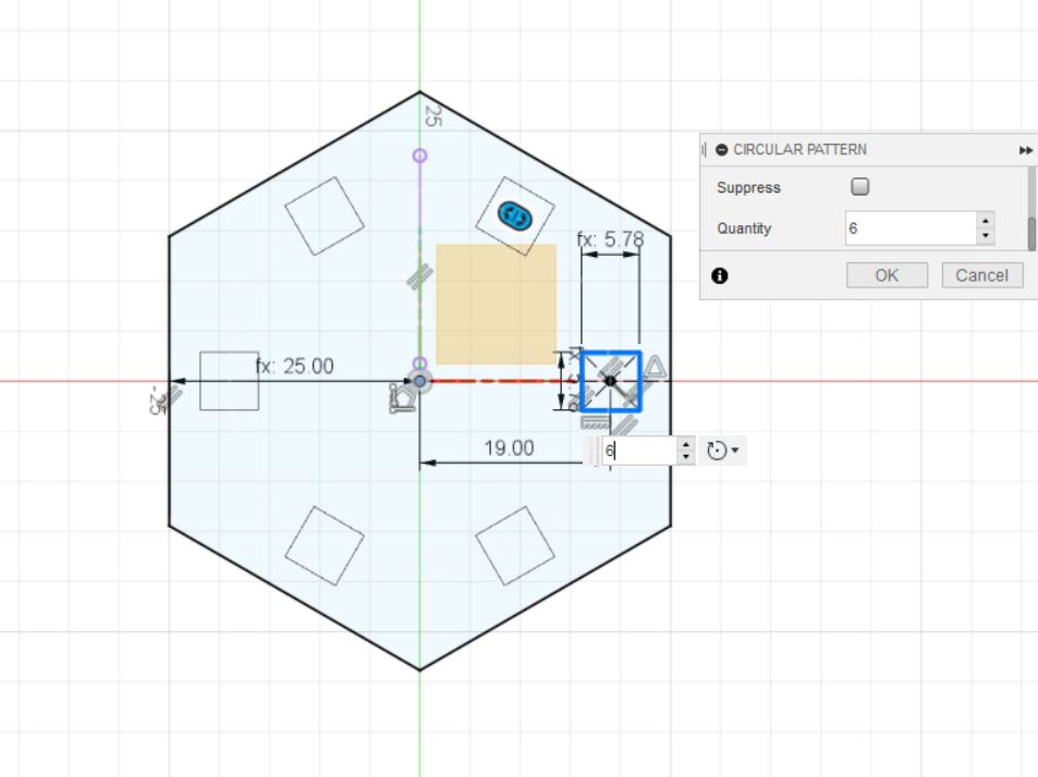
finally i added a rectangular hole in the middle
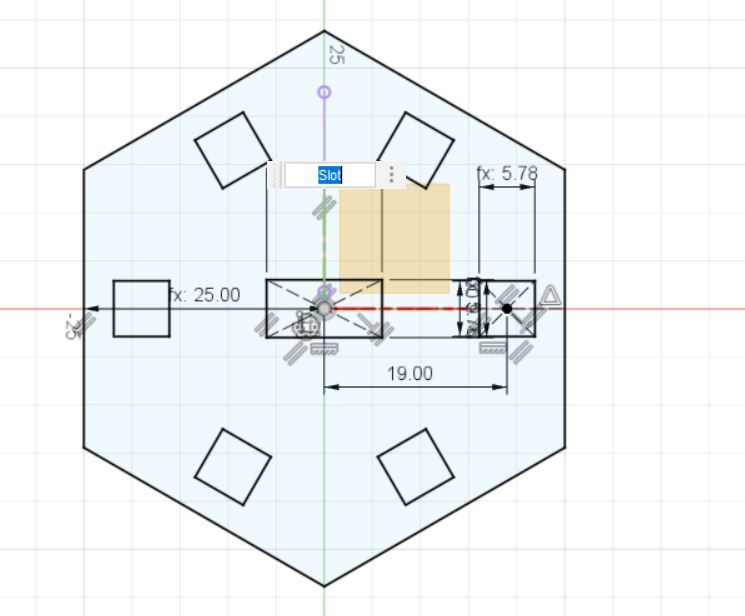
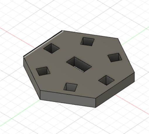
This is how the base looked like
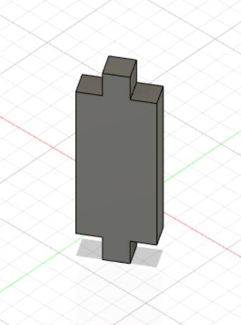
Then i designed the Wall that will give the base its thickness
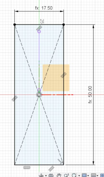
cut some of the wall sides to make somthing similar to inserts in the base
Here is the wall in 3D
Adding the Shapes together
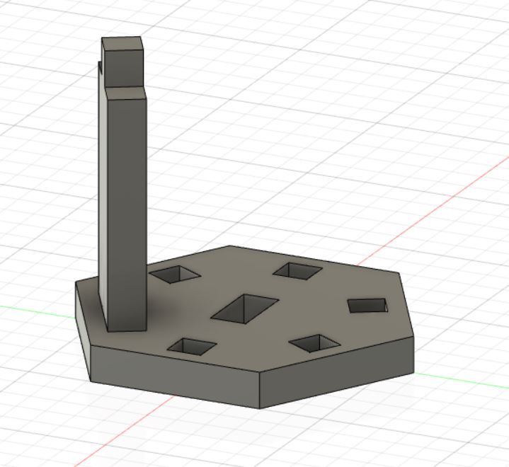
after adding more shapes
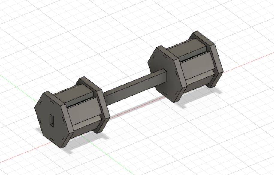
I needed to connect more shapes together so i added an arm that connects with middle hole
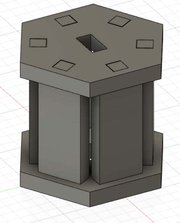
And Here is the Final Shape of the Dumbell
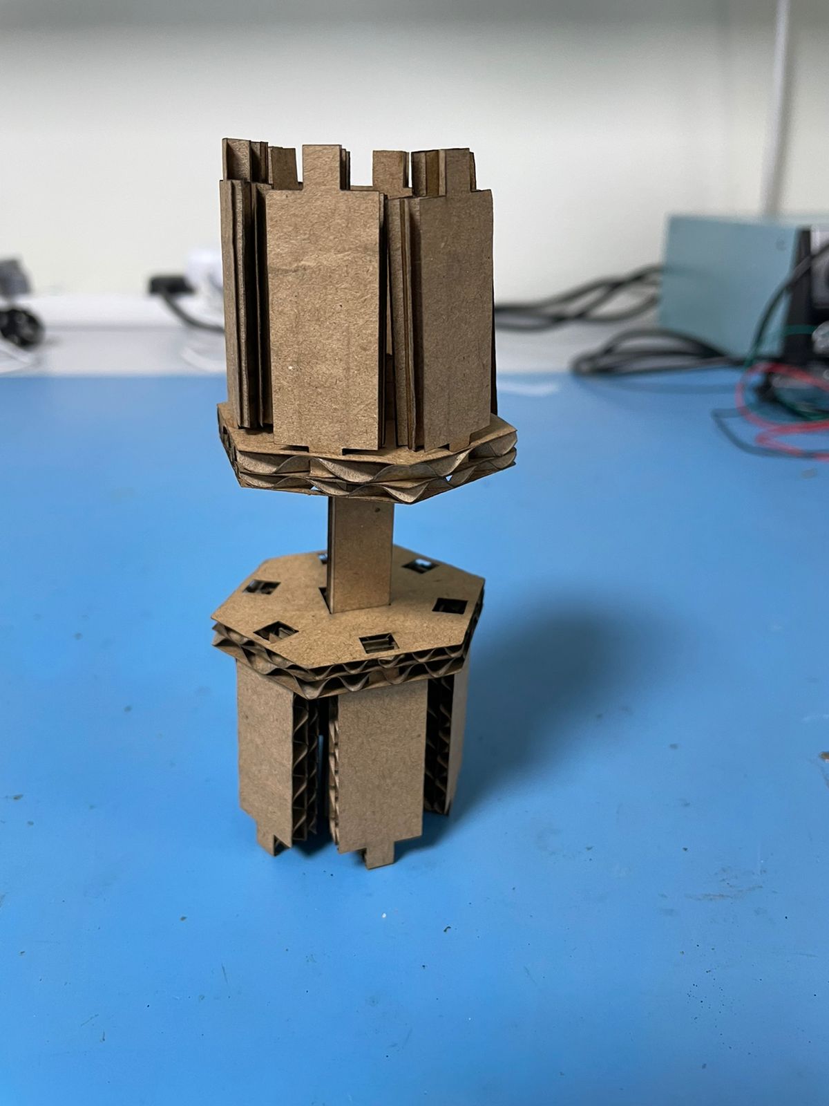
Here is how it turned out in cardboard, i think it needs more adjustment in the kerf setting
Group Project
3- Characterize your lasercutter's focus, power, speed, rate, kerf, joint clearance and types
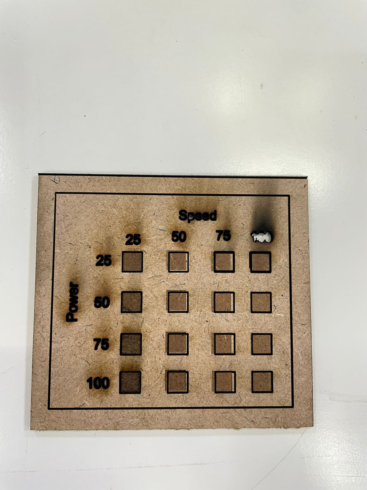
Here is the Results i got using the Laser Machine, The Material i used is MDF Wood, here are the results i got for laser engraving.
After that i went to try the kerf Adjustment, i did two tries, one with smaller sample and another one with bigger sample.
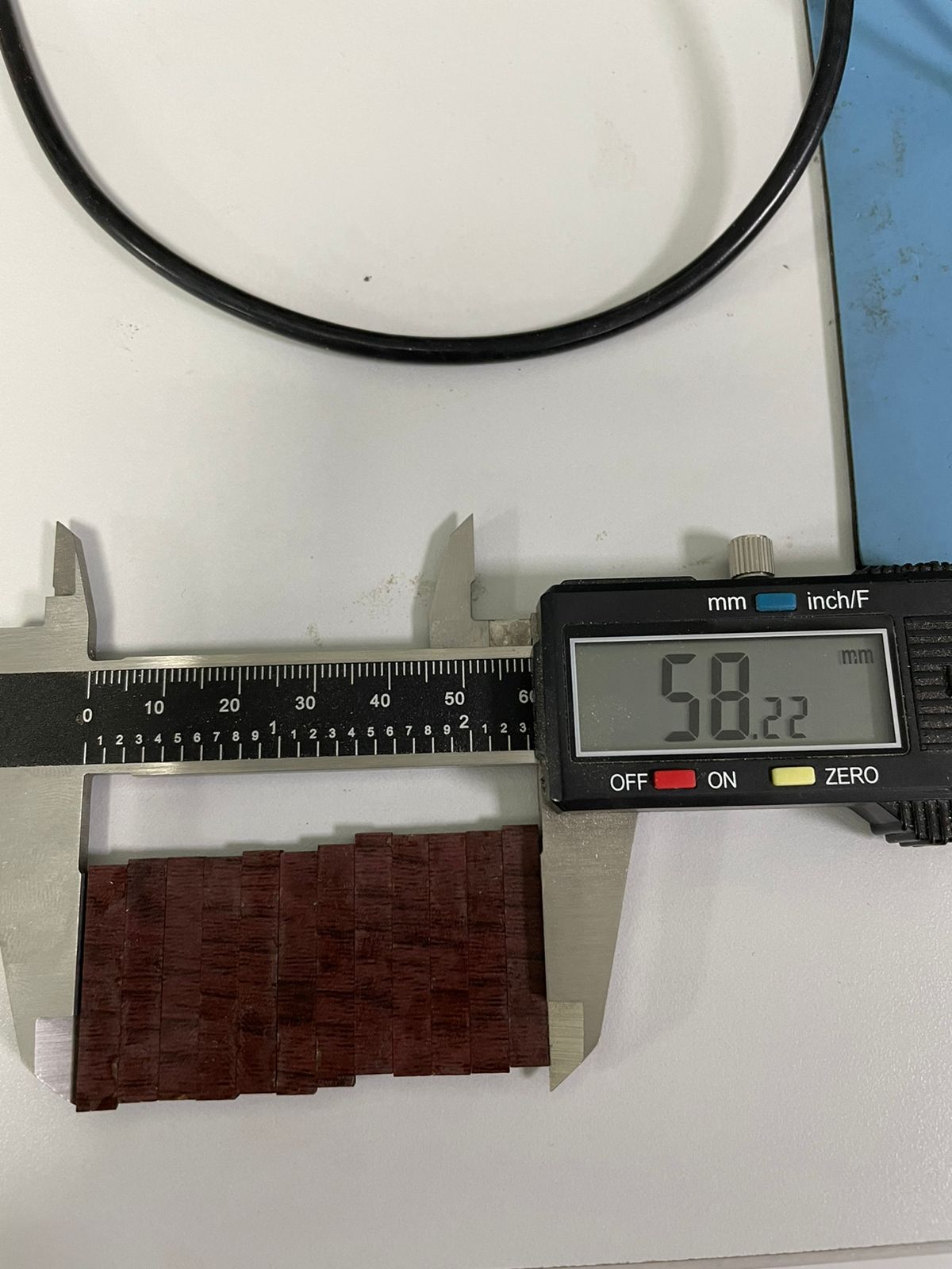
Here the total rectangle length = 60mm
number of rectangles = 12
rectangle length after engraving = 58.22mm
k = (60-58.22)/12 = 0.148mm
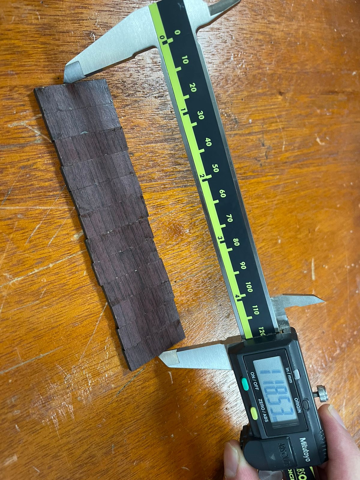
similarly here
Here the total rectangle length = 120mm
number of rectangles = 12
rectangle length after engraving = 118.53mm
k = (60-58.22)/12 = 0.1225mm
Files
| Source Files |
|---|
| Wolf.jpg |
| Wolf.pdf |
| Parametric_design_dumbell |
