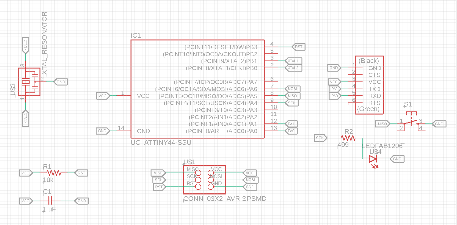
Individual Assignment:
1- Read the data sheet for your microcontroller
2- Use your programmer to program your board to do something
- Extra credit: try other programming languages and development environments
Group assignment:
3- Compare the performance and development workflows for other architectures
1- Read the data sheet for your microcontroller
For this week the assignment was program our board that was made in the Electronic Design week, but before that one most important things is read the datasheet of your microcontroller as it will be important to know more about your microcontroller.
One of the most important things that i always keep going back to is the attiny44 pinout.
I went back and forth alot between the pinout figure and my board schematic to make sure i know where is led and switch connected to which pin.

From the schematics i can see that i connected my led to SCK pin which is PA4 and the Switch to MISO which is pin PA5, knowing where i connected everything is important when programming later.
Its important to know the pinout of your board luckily the attiny44 has 14 pins, 2 for GND and VCC one for RST, and the rest can be programmable either as inputs or outputs.
2- Use your programmer to program your board to do something
Using Arduino IDE and Language
I tried programming the board using the Arduino IDE, using the arduino modified C++ language to write this simple button led code
With help of Eng Hashim he guided us on how to use the serial to display the state of the switch when its pressed, as it shows 1 when button is not pressed and 0 when button is pressed + turns on the led.
Using C Language
Also here with the help Eng hashim, i tried coding on C language before but it was only the basics without any devices, here i changed the code that eng. hashim made which the same as this, it turns on the Led with push of a button, i only changed the pins to the ones i am using now.Also one the things that should be taken into consideration is that there is a huge difference when using different languages in terms of memory, for example the C language consumes less memory when compared to the IDE language since C language is considered a low level language, to put it in simple terms the Processors understands quickly on the other hand arduino language consumes more memory since its a modified language and the process to witch the code communicates with compiler needs a longer route putting it simply, two pictures below show the difference between them.
