Electronics Design
Individual AssignmentAAA:
1- Redraw one of echo hello-world boards or something equivalent, add (at least) a button and LED (with current-limiting resistor) or equivalent input and output, check the design rules, make it, test it. Optionally, simulate its operation.
Group assignment:
2- Use the test equipment in your lab to observe the operation
of a microcontroller circuit board
extra credit: send a PCB out to a board house
Link
Redraw one of the echo hello-world boards
For this week I chose the attiny44 as my echo hello-world board, I learned how to use Autodesk Eagle to form the traces and to pick the positions of the components that are going to be soldered.learned how to use FlatCam for Engraving on the Board.
Here are the steps i took to recreate the attiny44 board using Eagle
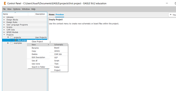
make a project in Eagle
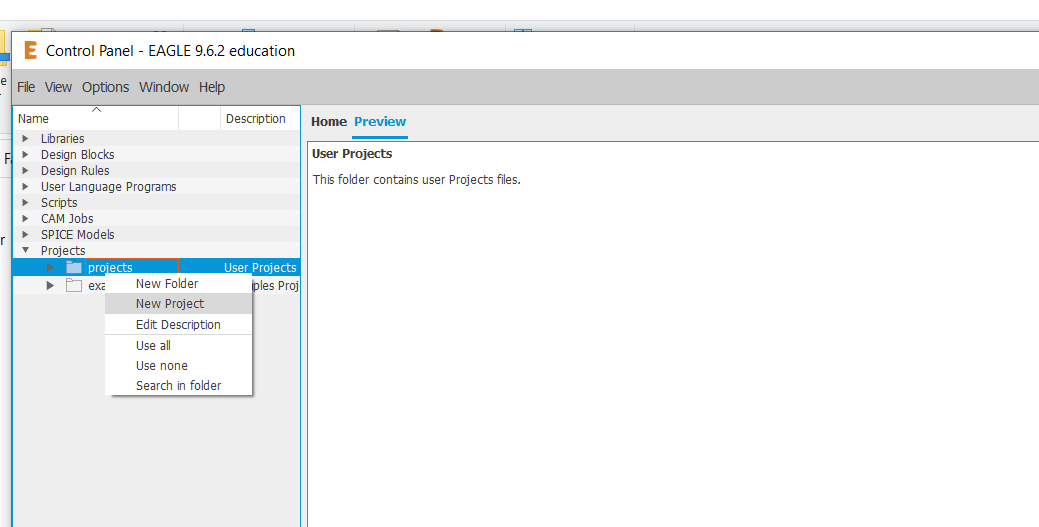
Click --> New --> Schematic
For this Board i took Reference of the components of the Attiny44 Board that i got from Here
and then proceded to add the parts in Eagle
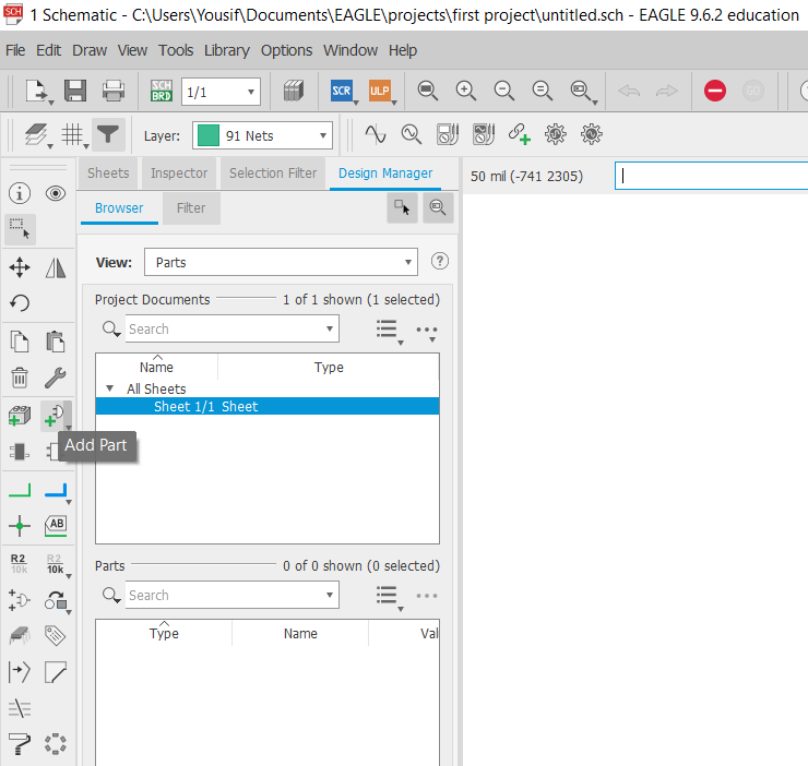
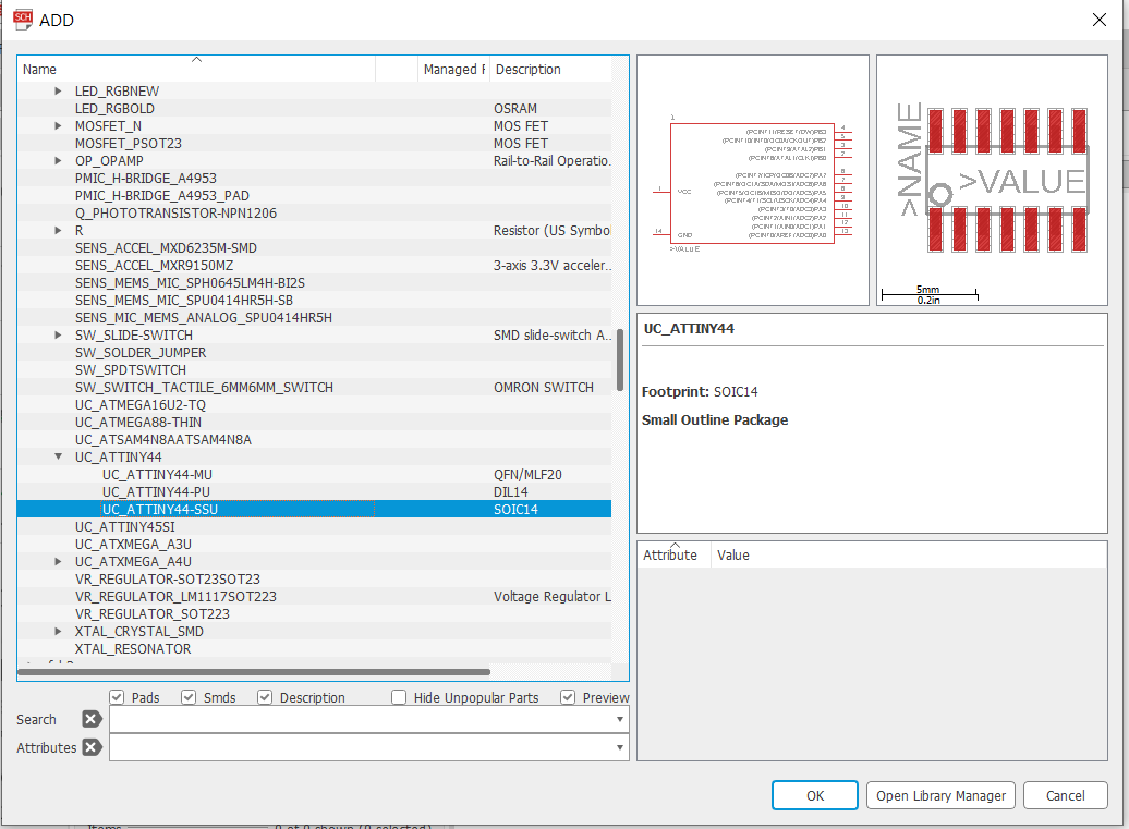
Adding the Attiny44
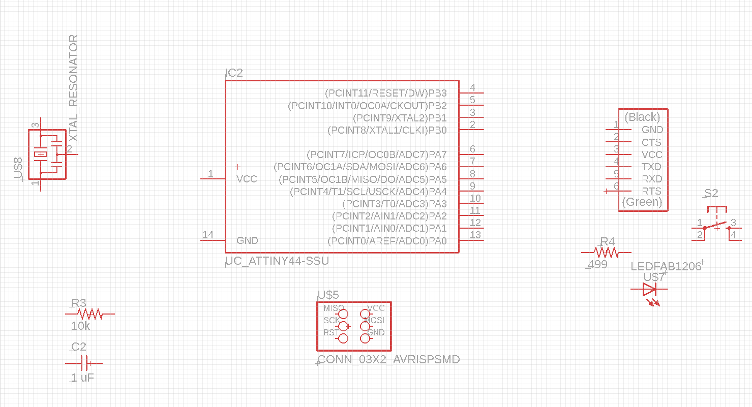
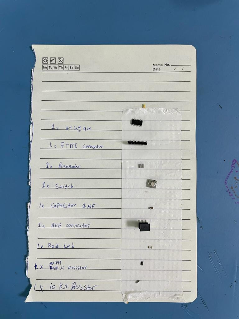
Here are the Components that will be used in this board + led + switch
1. 1x ATtiny44
2. 1x 10kΩ resistor
3. 1x 499Ω resistors
4. Crystal resonator
5. 1x Switch/button
6. 1x red LED
7. 1x FTDI
8. 1x 1uF capacitor
9. 1x 2x3 pin header
The 499Ω Resistor is for the LED, To calculate the Value of the Resistor i went to Led Datasheet and Looked for the values which are Forward Voltage and Forward Current.
Then I plugged these numbers in the Following Calculator to
the required resistance.
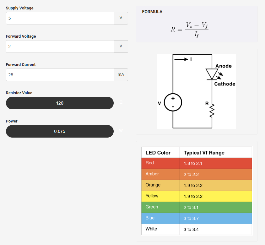
Forward Voltage = 2.0 V(datasheet)
Forward Current = 0.25 A(datasheet)
Supply Voltage = 5.0 V(Supply Voltage from PCB)
We Can see that the Value of the resistor is 120Ω.
This Resistor is smaller than least available resistor in the lab.
So i will be using 499Ω, which is the smallest one available.
To make the process of adding traces later easier we can add paths of each component's pin by adding labels to them
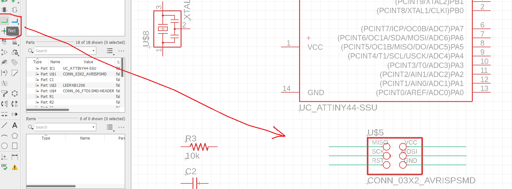
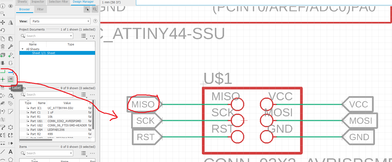
Then proceed to add labels to all of the component's pins

After the pins have been labeled click on Generate Board
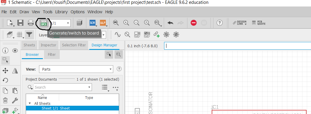
And It will take you to the page where we will make traces
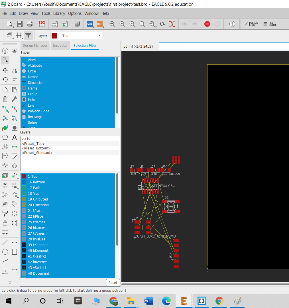
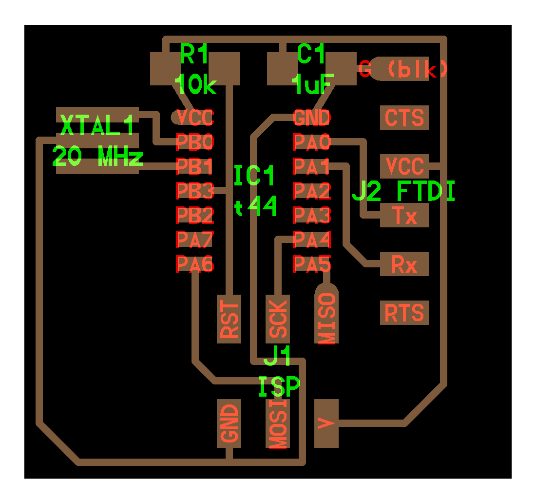
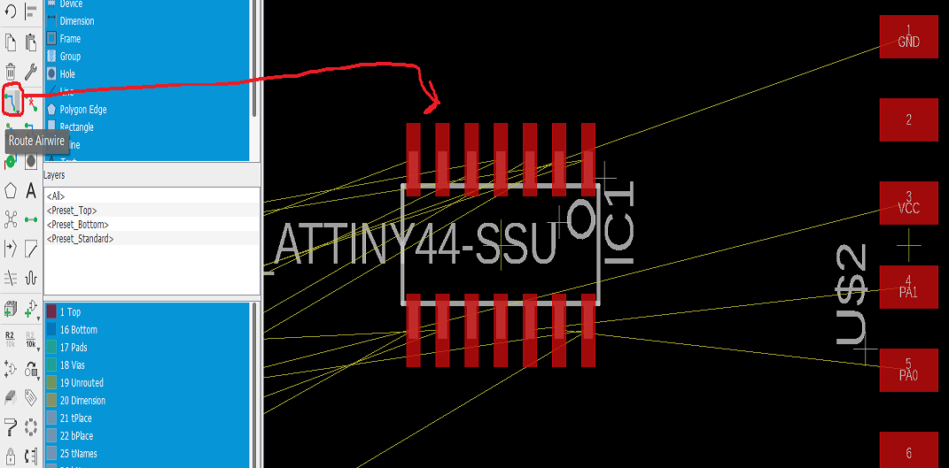
putting all the componenets and rearranging them is like a puzzle as the engineer used to say, it took me long a time to figure out the right orientation of each element and to make sure everything is ok. Start by moving each component to page and then click route airwire to connect between the elements.
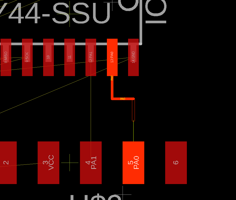
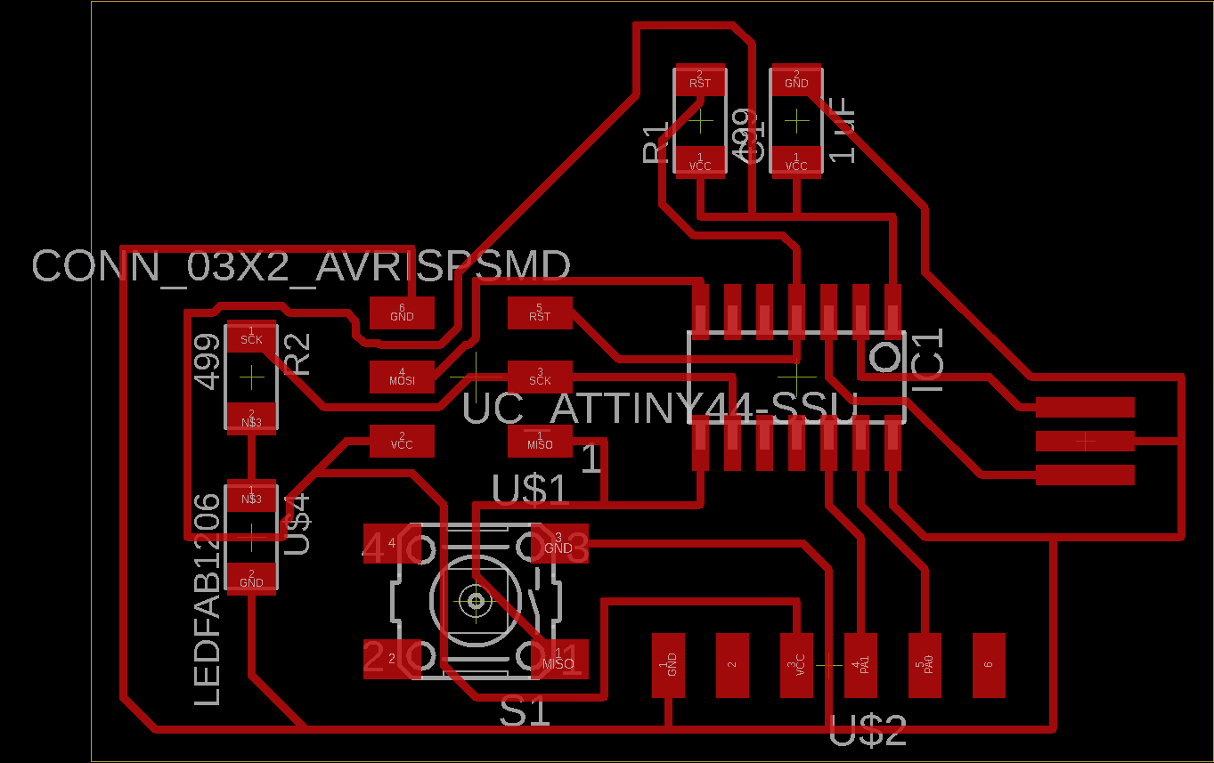
Finally after a lot time and effort i connected all of the componenets.
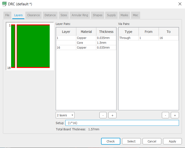
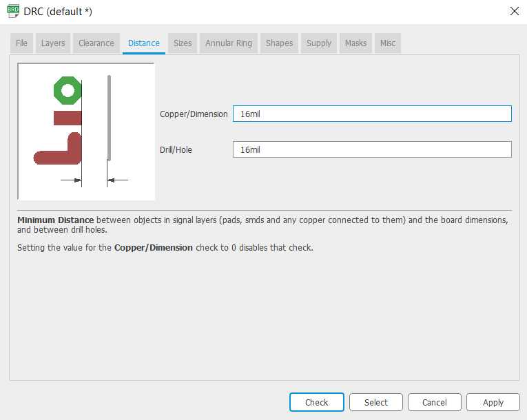
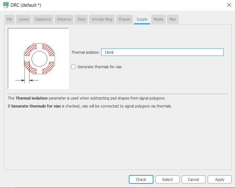
Then all is left in Eagle is to do two final checks, first the ERC when you click on it if no dialog box comes out or Error it means all the connections are ok, then DRC which will open the prefrences for board setting that are related to clearnces between the traces and such.
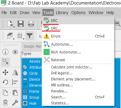
Its important in DRC that we check for stock thickness and clearances, since we are using 1/64" bit which is 1/64 = 15.62. we will use 16 mil for extra clearance.
![]()
After that Go to File --> CAM Processor
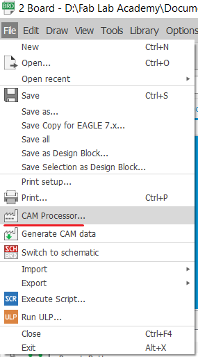
Process job
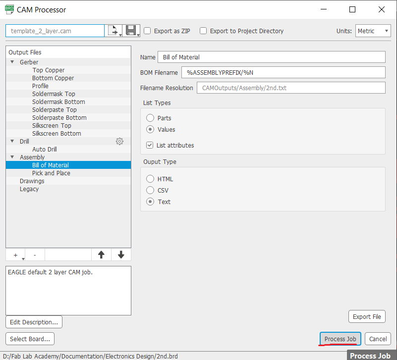
Save it to a folder
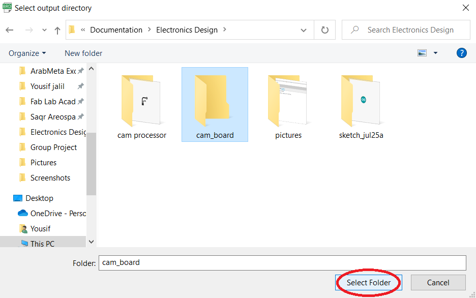
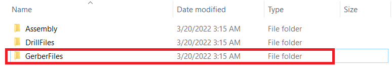
We are going to be interested into this folder
And particularly we are going to use these two files in Flat Cam Software
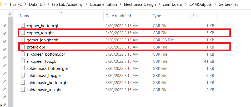
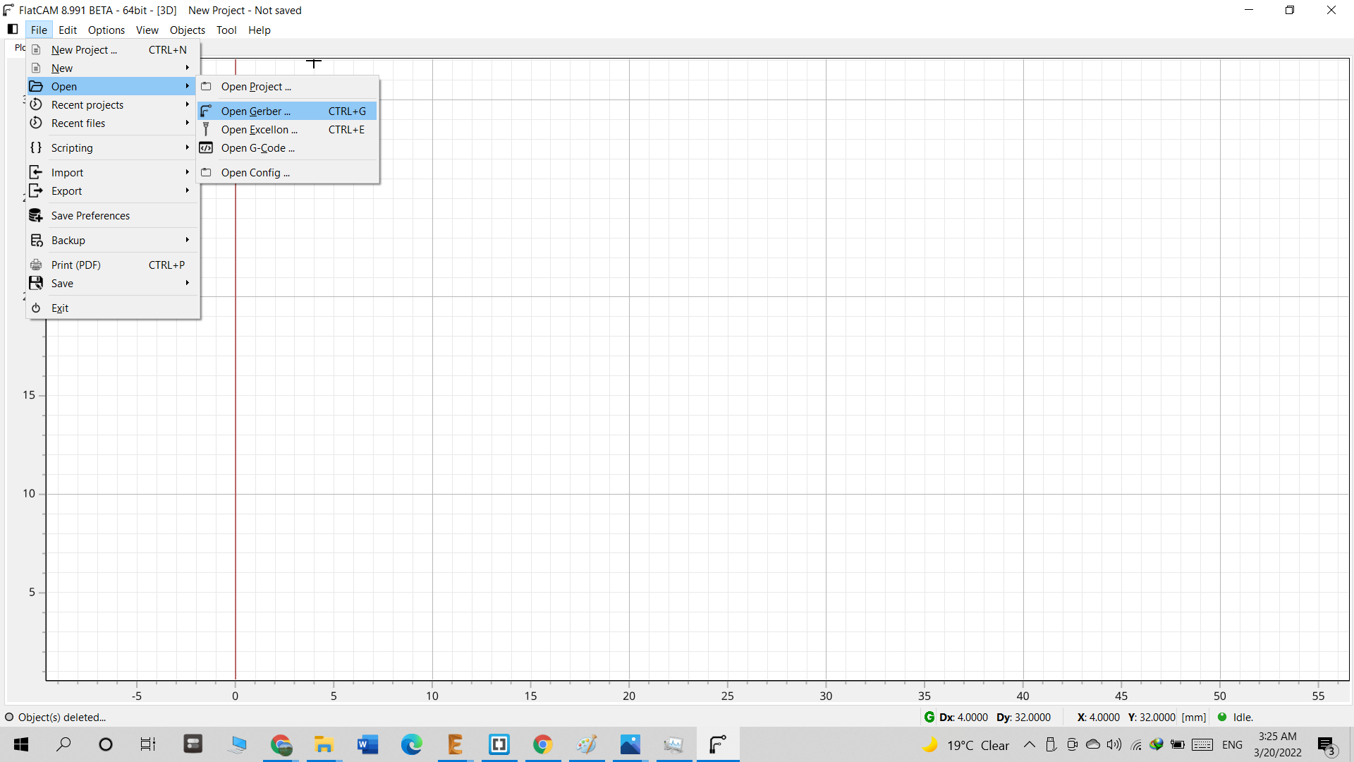
Open FlatCam go to --> File --> Open --> Open Gerber, Select these two files

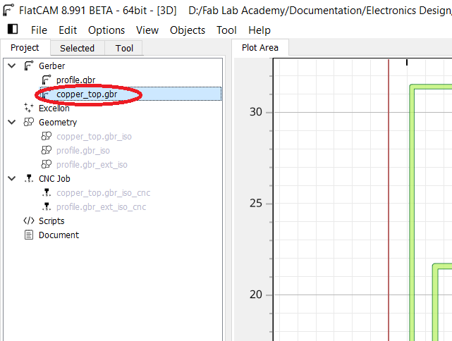
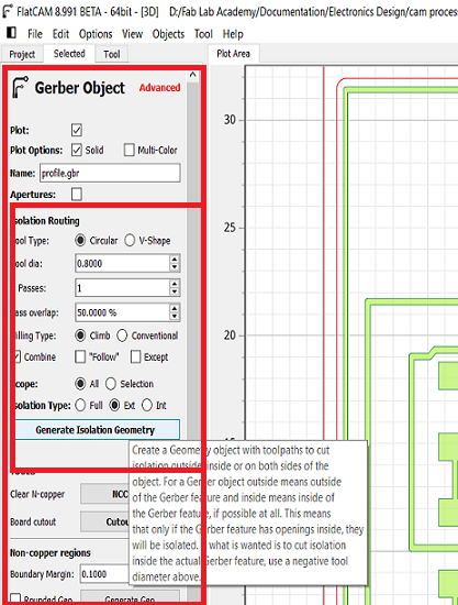
Then in Project Tab select the Copper_top
Go to the Select tab and edit
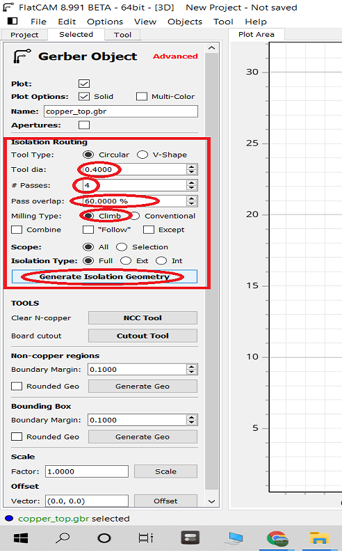
After That click on
Then go to
Now we do the same steps for the Outline, in Project Tab select the profile
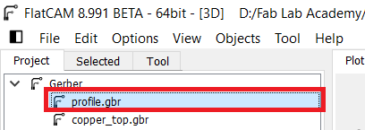
Go to the Select tab and edit
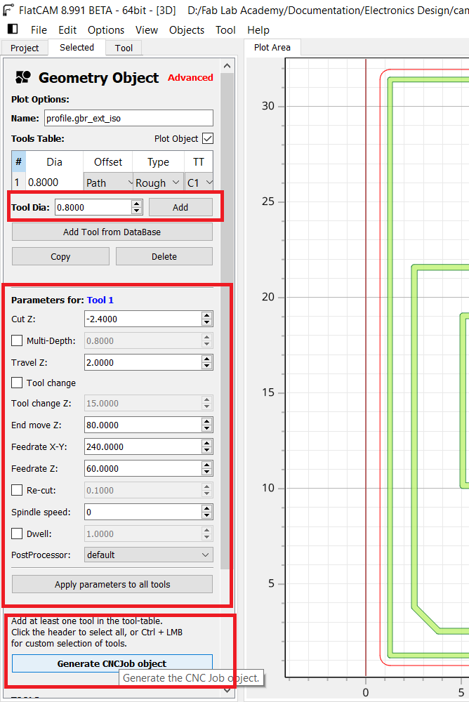
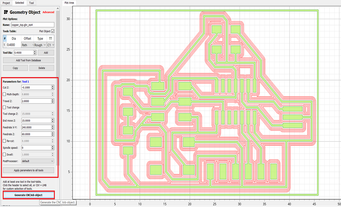
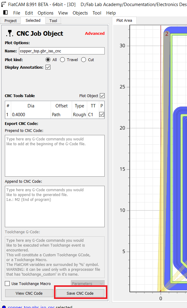
After That click on
Then go to
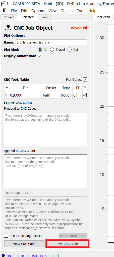
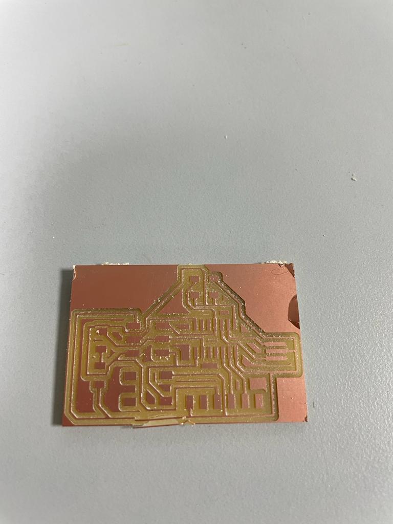
Now we have successfully generated our CNC files which will go to the Roland SRM Machine, and here we have the printed boards. i faced a few problems here,
in the first board everything was ok but when i tried to take the board out of the stock, I accidently removed some of the traces, as seen below
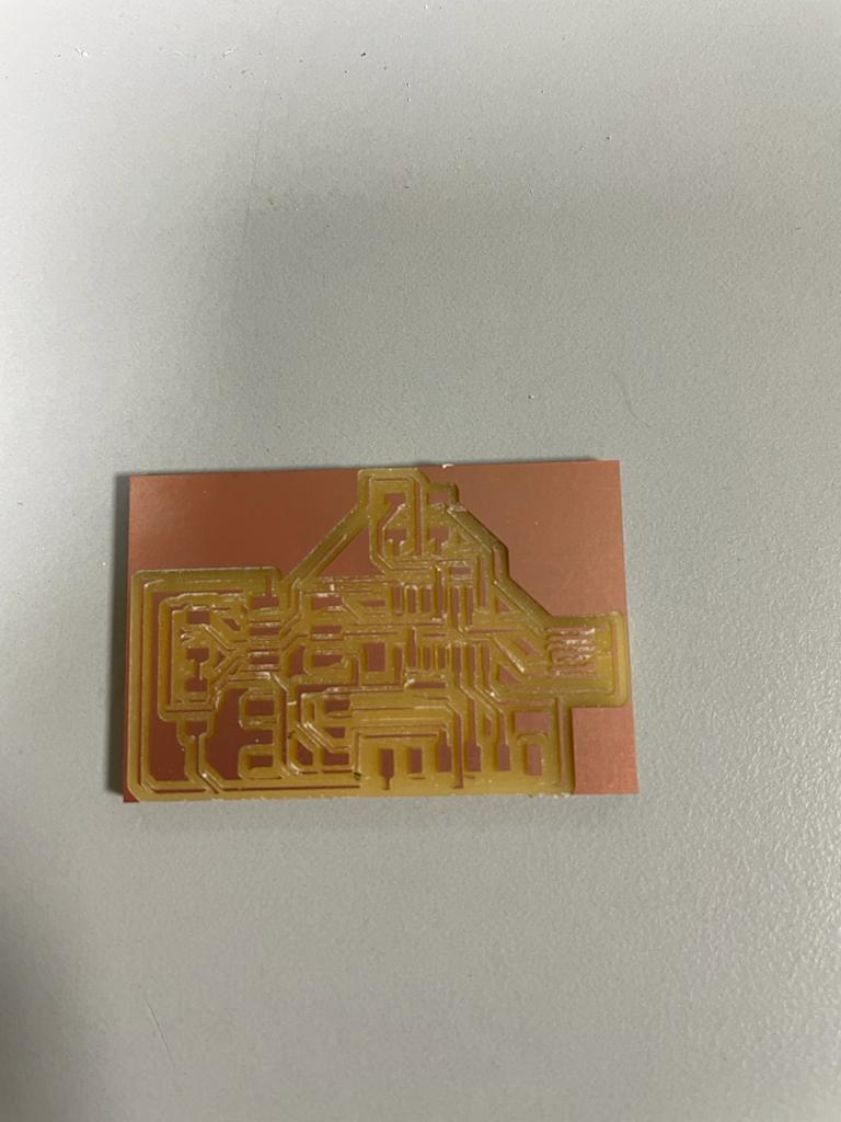
On the Second try i thought this time i will be careful and forgot to change the milling bit, i used the 1/32" to mill which lead to a completely unusable board,
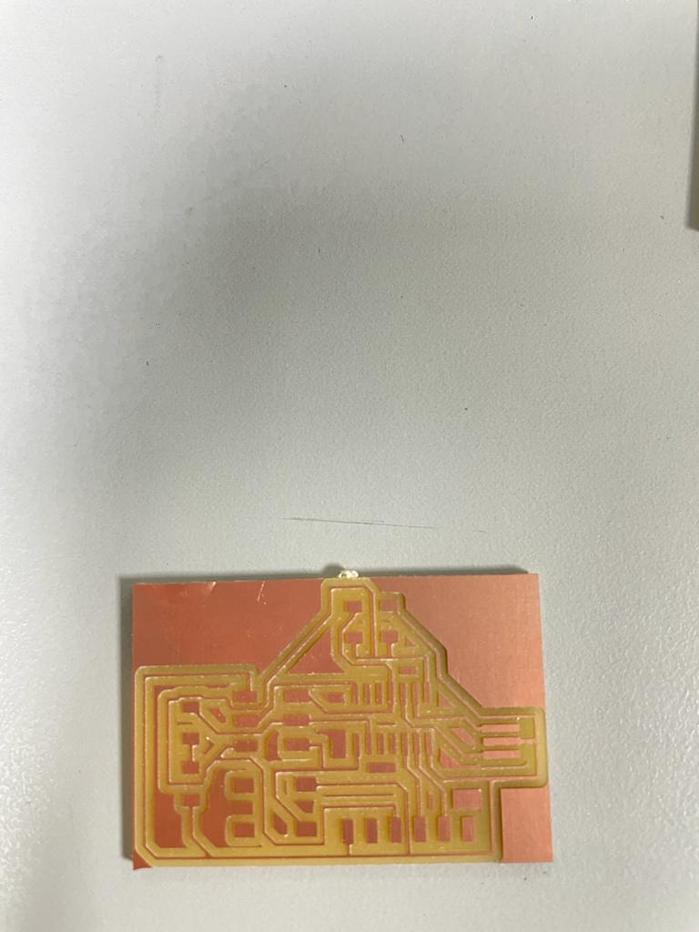
Now for sure third time the charm, i milled the board succesfully and took it out from the stock without damaging the traces :).
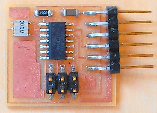
Next i gathered all the components for soldering
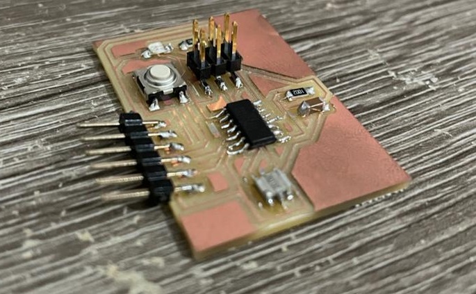
Here is the Soldered Board
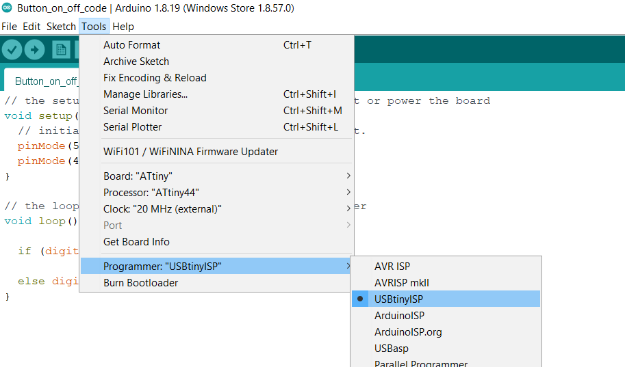
After soldering, time to test the board, Connect the board to ISP programmer that was done in Electronics Production week.
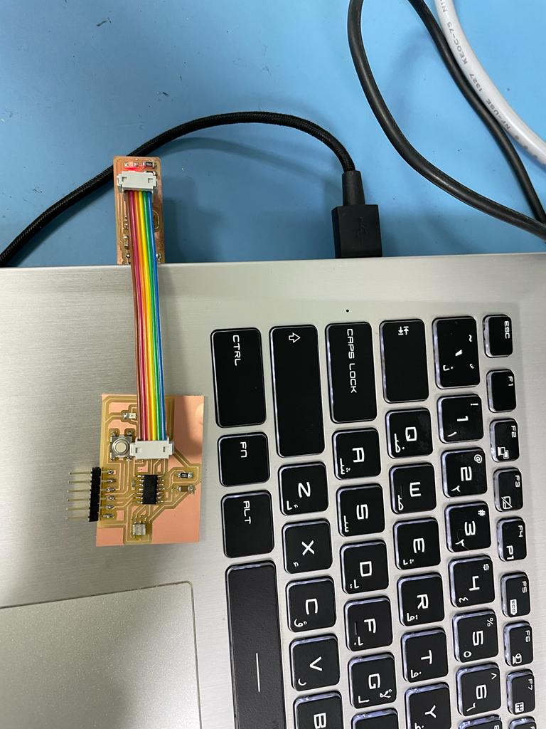
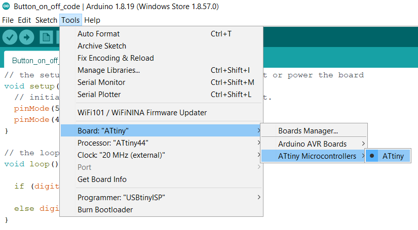
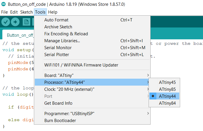
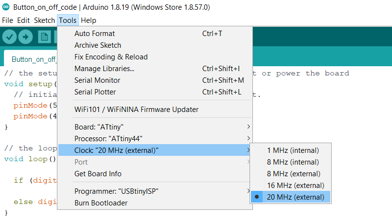
After that I connected the ISP Programmer into my laptop and used Arduino IDE to program the board. make sure to select your board configurations before uploading any code, i followed Sara's documentation at this point. After that, I opened Arduino IDE and I added the microcontroller that I will be programming which is attiny44.
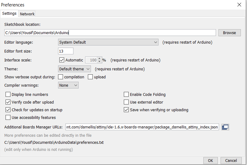
go to File --> Preferences --> Additional Boards Manager URLs --> paste the following URL --> Ok
https://raw.githubusercontent.com/damellis/attiny/ide-1.6.x-boards-manager/package_damellis_attiny_index.json
Then I uploaded this simple button code Code
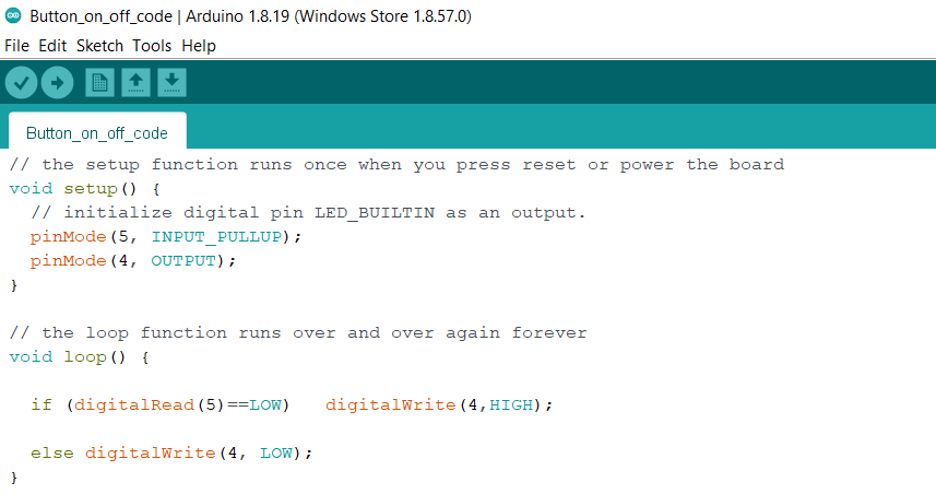
And it Works
Files
Linetest ClimbLinetest Conventional
Linetest Outline
Eagle Board File
Eagle Schematic File
....
