Individual Assignment:
1- add an output device to a microcontroller board you've designed,
and program it to do something.
Group assignment:
2- measure the power consumption of an output device.
Link
1- add an output device to a microcontroller board you've designed,
and program it to do something.
For this assignment, i wanted to control motors in order to learn more about them, since i will be using them in my final project.
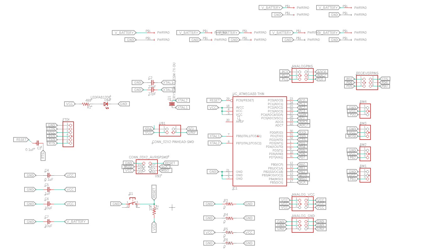
I desgined a new board that hopefully will help me during future assignments. i will be using Atmega328p Microcontroller as it very flexible and easy to use. I tried to make use of all the pins that are available to get most out of my board, Also I added a options to controll brushless motors and servo motors as this will be my goal for this assignment.
The Schematic
The Board
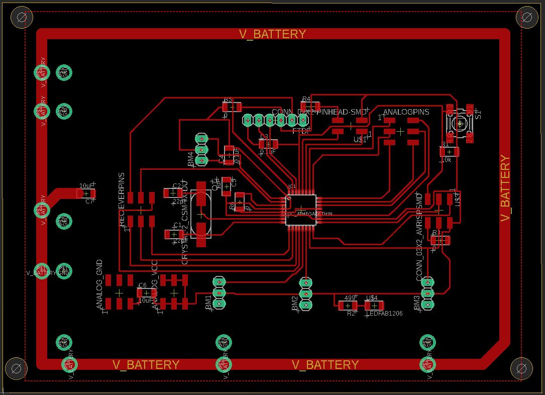
I Have Added as much inputs and outputs as i can to make sure that i can controll a wide range of sensors and devices.
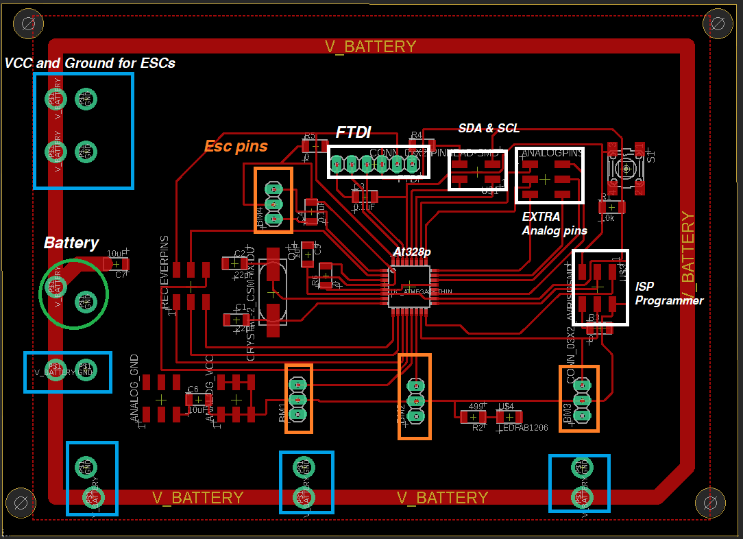
Here you can see the added pins.
The green circle is for the battery
The Blue rectangles represent where the ESCs(Electronic speed Controllers) power and ground are going
The orange rectangles are for the PWM(pulse with modualating) pins on the At328p controller which are used to controll the brushless and servo motors.
The white ones are for FTDI, ISP, SDA & SCL and Extra anolog pins
The Servo motor i will be using is Servo Motor SG-90
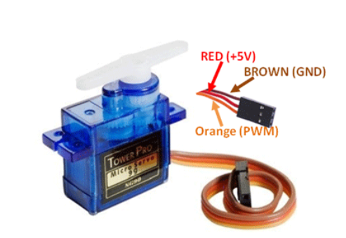
I connected the Motor pins and a potentiometer to the PCB and uploaded this code to it
#include   // add servo library

Servo myservo;  // create servo object to control a servo

int potpin = 0;  // analog pin used to connect the potentiometer
int val;    // variable to read the value from the analog pin

void setup() {
  myservo.attach(9);  // attaches the servo on pin 9 to the servo object
}

void loop() {
  val = analogRead(potpin);            // reads the value of the potentiometer (value between 0 and 1023)
  val = map(val, 0, 1023, 0, 180);     // scale it to use it with the servo (value between 0 and 180)
  myservo.write(val);                  // sets the servo position according to the scaled value
  delay(15);                           // waits for the servo to get there
}
The Result
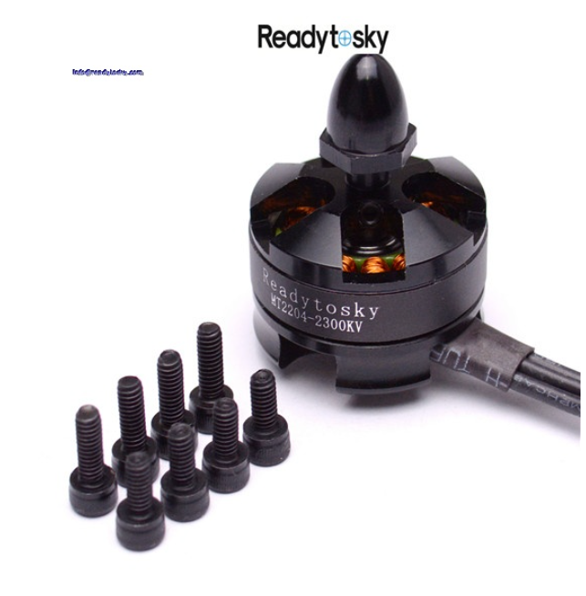
Similarly I tried the same using the brushless motor, the brushless motor i will be using is Readytosky MT2204 2300KV Brushless motor and A 30A ESC that comes with it
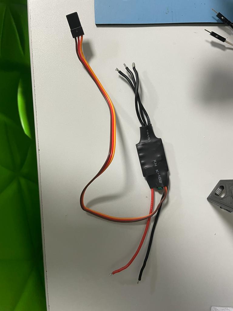
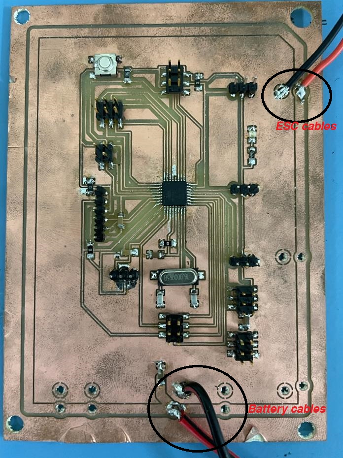
I Have soldered the battery cables to the board and ESC cable, Then before connecting the battery, I uploaded this code to control the motor with a potentiometer
#define pinA 2

#include

Servo myservo;  // create servo object to control a servo

int potpin = 0;  // analog pin used to connect the potentiometer
int val;    // variable to read the value from the analog pin

void setup()
{
  myservo.attach(9);  // attaches the servo on pin 9 to the servo object
}

void loop()
{
  val = analogRead(potpin);            // reads the value of the potentiometer (value between 0 and 1023)
  val = map(val, 0, 1023, 0, 179);     // scale it to use it with the servo (value between 0 and 180)
  myservo.write(val);                  // sets the servo position according to the scaled value
  delay(15);                           // waits for the servo to get there
}
Files
BoardSchematic
